25 minute read
Novel Design and Implementation of Kuwait’s First Smart Multilateral ...part (01
Next Article

Novel Design and Implementation of Kuwait’s First Smart Multilateral Well with Inflow Control Device and Inflow Control Valve for Life-cycle Reservoir Management in High Mobility Reservoir, West Kuwait part (01)
By
Om Prakash Das, Khalaf AI-Enezi, Muhammad Aslam, Taher EI-Gezeeri, Khalid Ziyab, Kuwait Oil Company; Steven R. Fipke, Steven Ewens, Halliburton
Abstract
Increased hydrocarbon recovery and accelerated production from ultra-high water mobility oil-wet reservoir requires the application of advanced well completion technologies to address premature water breakthrough, reservoir management, production management and extended reservoir contact from a single well location. The Burgan Reservoir of Minagish Field, West Kuwait has active aquifer, very high permeability sands associated with active faults and contain highly viscous reservoir fluid with downhole viscosity of 40cp, enhances water mobility and resulted in premature water breakthrough with increasing water cut trend within few months of production as confirmed from well performance of existing horizontal wells. This has resulted in to nonuniform reservoir depletion, by-passed oil regions and low oil recovery.
The Kuwait’s first smart level-4 multilateral well was completed in Burgan reservoir by combining the Level-4 junction along with stacked dual lateral completion having customized viscosity independent Inflow Control Device (ICD), customized two Inflow-Control Valves as well as down hole gauges, wide operating range Electrical Submersible Pump (ESP), suitable wellheads, X-MAS tree and Integrated surface panel for real time data monitoring.
The smart multilateral well has assisted in addressing premature water breakthrough, enhanced dry oil production and facilitated uniform depletion, which results in improved hydrocarbon recovery. The paper covers the customized design of smart Level-4 multilateral well by taking in to account the reservoir and its fluid characterization, well architecture, implementation and specially designed invert emulsion drilling fluid for effective wellbore cleanup to achieve formation virginity. The improved reservoir management and production management results are also mentioned in this paper.
Introduction
The advance smart multilateral well equipped with Inflow Control Device (ICD) and Inflow Control Valve (ICV) along with downhole gauges is identified as the optimum solution to accelerate oil production rate, maximize reservoir contact from a single well location and achieve adequate proactive reservoir management as well as production management to maximize oil recovery in high water mobility Burgan reservoir of Minagish field, West Kuwait. The Minagish field located in the West Kuwait (figure 1) is a north-south trending anticline with hydrocarbon contained in six major reservoirs ranging in age from early Jurassic to late Cretaceous and consists of both sandstone and carbonate reservoirs. The Burgan sandstone reservoir is lying at the crest of Minagish Field. The lower part of reservoir consists of massive channel sand and the upper part of reservoir contains vertically stacked thin laminated sand bodies with extensive lateral facies variation (figure 2). The
lower part of the Burgan Reservoir has lower part of the Burgan Reservoir has active bottom water drive whereas the active bottom water drive whereas the upper part of reservoir has edge water upper part of reservoir has edge water drive system. The reservoir contains drive system. The reservoir contains high permeability sands in order of high permeability sands in order of few Darcy associated with active faults few Darcy associated with active faults and highly viscous reservoir fluid with and highly viscous reservoir fluid with viscosity of about 40cp at reservoir viscosity of about 40cp at reservoir condition. In addition the reservoir condition. In addition the reservoir contains friable sands and requires contains friable sands and requires reliable sand control completions. reliable sand control completions. The Inflow Control Device (ICD) The Inflow Control Device (ICD) completions with suitable sand screen completions with suitable sand screen are selected for sand face completion to are selected for sand face completion to combine the advantage of sand control combine the advantage of sand control and flow control across sand face. and flow control across sand face.
The economic advantage of drilling The economic advantage of drilling several laterals from a single wellbore several laterals from a single wellbore with the ability to control and regulate with the ability to control and regulate production and inflow by controlling production and inflow by controlling severe water coning and premature severe water coning and premature water breakthrough in Burgan reservoir water breakthrough in Burgan reservoir resulted in to optimized and cost resulted in to optimized and cost effective field management. Further effective field management. Further the increased hydrocarbon reserve the increased hydrocarbon reserve recovery and accelerated production recovery and accelerated production with improved reservoir management with improved reservoir management have been recognized as the key have been recognized as the key business incentives by implementing business incentives by implementing this technology on “Well A” and this technology on “Well A” and “Well B” of Burgan reservoir first “Well B” of Burgan reservoir first time in Kuwait. Moreover the smart time in Kuwait. Moreover the smart multilateral wells with commingled multilateral wells with commingled completions leveraged with intelligent completions leveraged with intelligent well technology is the key technology well technology is the key technology solution to reduce the number of solution to reduce the number of wells required to develop the Burgan wells required to develop the Burgan structure and thereby to minimize structure and thereby to minimize the capital as well as operational the capital as well as operational expenditure. expenditure.
Burgan Reservoir Challenges: Burgan Reservoir Challenges:
The lower section of the Burgan The lower section of the Burgan sandstone reservoir consists of a sandstone reservoir consists of a braided river system with stacked braided river system with stacked channel sand bodies having very high channel sand bodies having very high horizontal and vertical permeability horizontal and vertical permeability in the order of few Darcy associated in the order of few Darcy associated with underlying active aquifer. The with underlying active aquifer. The combination of high oil viscosity, oil combination of high oil viscosity, oil wet reservoir characteristics, very high wet reservoir characteristics, very high water mobility associated with very water mobility associated with very high permeability and presence of high permeability and presence of fault networks (figure 3) connected to fault networks (figure 3) connected to aquifer accelerates water movement! aquifer accelerates water movement! (K.Al-Enezi et.al, O.P. Das et.al, 2010) (K.Al-Enezi et.al, O.P. Das et.al, 2010) inside reservoir and results in premature inside reservoir and results in premature water breakthrough in existing vertical water breakthrough in existing vertical as well as horizontal wells, in spite of as well as horizontal wells, in spite of maintaining highest stand-off from maintaining highest stand-off from OWC. The well performance of a OWC. The well performance of a conventional vertical and a horizontal conventional vertical and a horizontal well is detailed in figure 4. well is detailed in figure 4.
The combination of non-uniform The combination of non-uniform inflow profiles and premature water inflow profiles and premature water breakthrough across horizontal section breakthrough across horizontal section resulted in non¬uniform reservoir resulted in non¬uniform reservoir depletion and thereby the oil recovery depletion and thereby the oil recovery has impacted significantly from has impacted significantly from Burgan reservoir. In addition the Burgan reservoir. In addition the Burgan reservoir lies in the crest part of Burgan reservoir lies in the crest part of Minagish Field (figure 1) which limits Minagish Field (figure 1) which limits the surface locations for drilling wells the surface locations for drilling wells to effectively deplete the reservoir. The to effectively deplete the reservoir. The upper part of Burgan reservoir consists upper part of Burgan reservoir consists of complex laminated thin channel of complex laminated thin channel sand and shale (figure 2) associated sand and shale (figure 2) associated with faults networks (figure 3) poses with faults networks (figure 3) poses several drilling and geo-steering several drilling and geo-steering challenges.challenges.
Business Goals Associated with Business Goals Associated with Smart Multilateral Well Smart Multilateral Well
Based upon the reservoir Based upon the reservoir challenges and lessons learned challenges and lessons learned from previously implemented well from previously implemented well completion techniques, the following completion techniques, the following business goals were considered for business goals were considered for smart multilateral wells. smart multilateral wells. a. a. Maximize economic performance Maximize economic performance of the reservoir. of the reservoir. b. b. Enhance sustained dry oil Enhance sustained dry oil production by addressing premature production by addressing premature water breakthrough. water breakthrough. c. c. Maximize reservoir contact from a Maximize reservoir contact from a single well location and minimize single well location and minimize number of wells. number of wells. d. d. Pro-active reservoir and production Pro-active reservoir and production management by increasing management by increasing knowledge of reservoir dynamic knowledge of reservoir dynamic characteristics from real time characteristics from real time measurement of pressure, measurement of pressure, temperature and downhole flow temperature and downhole flow
rate of oil, water and gas. rate of oil, water and gas. e. e. Ability to make right time decisions Ability to make right time decisions to optimize inflow control valves to optimize inflow control valves position for controlling production position for controlling production from each leg of multilateral wells from each leg of multilateral wells to minimize water production and to minimize water production and enhance dry oil production. enhance dry oil production. f. f. Achieve uniform reservoir Achieve uniform reservoir depletion, minimize by-passed oil depletion, minimize by-passed oil regions, and maximize oil recovery. regions, and maximize oil recovery. g. g. Maximize Net Present Value Maximize Net Present Value (NPV). (NPV). h. h. Minimize capital and operational Minimize capital and operational expenditure. expenditure.
In order to achieve the business goals In order to achieve the business goals by mitigating reservoir challenges, the by mitigating reservoir challenges, the technology selection workflow has technology selection workflow has been developed (figure 5) to select the been developed (figure 5) to select the most suitable technology. most suitable technology.
Smart Multilateral Well Smart Multilateral Well Architecture and Design Architecture and Design
The smart multilateral well design The smart multilateral well design was customized to install inflow control was customized to install inflow control device completion at sand face for both device completion at sand face for both mother bore as well as upper lateral, mother bore as well as upper lateral, intelligent completion including two intelligent completion including two inflow control valve, downhole gauges, inflow control valve, downhole gauges, feed through packers and Level-4 feed through packers and Level-4 cemented junction to provide fullcemented junction to provide fullbore access to mother bore and upper bore access to mother bore and upper lateral. Further the ESP completion lateral. Further the ESP completion along with by-passed tubing was along with by-passed tubing was kept independent from intelligent kept independent from intelligent completion by means of installing 9 completion by means of installing 9 5/8” tubing to mount hydraulic and 5/8” tubing to mount hydraulic and electrical control lines of downhole electrical control lines of downhole intelligent completion to ease the ESP intelligent completion to ease the ESP replacement workover jobs without replacement workover jobs without interfering with downhole intelligent interfering with downhole intelligent completions. Further the provision completions. Further the provision was made inside intelligent completion was made inside intelligent completion by placing hydraulic control ball by placing hydraulic control ball valve to have ability for conducting valve to have ability for conducting production logs or any other required production logs or any other required surveillance jobs through ESP by-pass surveillance jobs through ESP by-pass tubing to monitor the performance of tubing to monitor the performance of mother bore. The opening and closing mother bore. The opening and closing of all the hydraulic valves are from of all the hydraulic valves are from surface without well intervention. The surface without well intervention. The selected well completion design by selected well completion design by
utilizing the most reliable equipment minimizes the needs of surveillance jobs, workover jobs related to water shut-off and other workover jobs for intelligent completions. In addition the suitable wellheads and X-MAS design was customized to incorporate the intelligent completion and ESP completion separately. The well schematic of smart multilateral “Well A” and “Well B” is shown in figure 6. The selection and design of inflow control device, intelligent completion, level-4 multilateral junction and ESP completion system are detailed in the following sections.
Suitable Inflow Control Device (ICD) Selection and Design
There are different passive ICD types available in the industry categorized mainly as friction based and restriction based ICD system. The channel and tube type lCD’s are friction based system uses friction to create pressure drop for inflow balancing across sand face and are highly dependent upon viscosity. The restriction type lCD’s are mainly classified as nozzle type and orifice type. The pressure drop through restriction type ICD is a function of density and fluid velocity. Further the restriction type ICD are independent of fluid viscosity for a wide range of viscosity values.
The selection of appropriate ICD type is the main success factor for horizontal or multilateral wells and is highly dependent on reservoir fluid properties specifically the viscosity of oil and water at in-situ conditions, reservoir permeability and the mobility of low viscosity fluids such as formation water and gas. The following objectives were considered for ICD completion to complete the horizontal openhole section of mother bore and upper lateral of smart multilateral wells. a. Facilitate uniform inflow across
entire horizontal production section of both main mother bore and upper lateral. b. Control water production from relatively high permeability layers upon water breakthrough. c. Automatic adjustment capability to compensate changes in well inflow profile over production life of wells. d. Provide uniform sweep efficiency across sand face. e. Minimize annular flow. f. Minimize pressure drop through
ICD housing in order to improve flowing bottom hole pressure (FBHP) in both mother bore and upper lateral. g. Minimize by-passed oil regions and maximize oil recovery. h. Maximize production life of wells.
Based upon the objectives and by considering the physics and chemistry of fluid flow inside the Burgan reservoir under well operating conditions of smart multilateral well, the most suitable nozzle type Inflow control device completion was selected. Usually the pressure drop through nozzle based ICD system is described by the Bernoulli’s equation, because of the pressure drop through a nozzle is a result of static energy in the fluid being converted to kinetic energy as it is flowing through the restricted nozzle throat area. However, the Bernoulli’s equation applied to the flow through nozzle assumes no friction losses and viscosity effects are negligible, Incompressible fluid flow (density is constant), flow is steady and inviscid (requirement of Euler validity) and also the equation relates to the fluid states at two points along a single stream line. Based upon these assumptions the pressure drop through the nozzle is given by:
In the case of highly viscous fluid flow through nozzle the flow regime falls mostly in the laminar flow region and the discharge coefficient CD is variable depending upon Reynolds number as detailed by2 (J. Eric Lauritzen et.al and lngvild Berg Matniussen et. al 2011) through three phase flow loop testing. Further the other independent studies by various authors3-7 suggests that the pressure drop through nozzle depends on aspect ratio (ratio of nozzle throat length to the throat diameter), throat Reynolds number, Beta β ratio and nozzle entry shape (Sharp edged entry, smooth entry etc.).The smooth fluid entry nozzles such as long radius nozzle, venturi nozzle, smooth entry orifice etc. has high discharge coefficient as compared to sharp edged entry nozzle / orifice which minimizes the pressure drop through nozzles of ICD completions and maximizes the FBHP. Also the variation of discharge coefficient versus Reynolds number for smooth entry nozzle is low under applicable range of Reynolds number in ICD completion. Moreover the nozzle exit section design plays an important role in pressure recovery as lost during the flow through nozzle throat. The better pressure recovery increases the pressure downstream of the nozzle and thereby increases the FBHP of the well. In addition the proper design of nozzle entry and exit minimizes the erosion of nozzle and ensures long term performance of K’D completion.
The properly designed venturi nozzle based ICD module is selected for the Smart Multilateral “Well A” and “Well B” of Minagish Burgan reservoir. The smaller nozzle sizes (1.6 mm and 2.5 mm) were selected to achieve adequate choking of water phase upon breakthrough. Further the variable nozzle housing for ICD module were selected to place required number of nozzles in each compartment based upon the reservoir fluid flow dynamics inside reservoir along with variation in
permeability and water mobility across horizontal production section of the wellbore to meet the objectives of ICD completion.
The flow rate versus pressure drop characteristics by considering oil viscosity, water viscosity, oil density and water density at reservoir conditions of Burgan reservoir were analyzed based on the supplier’s provided discharge coefficient at various Reynolds number and the discharge coefficient obtained by independent experiment performed by8 (Jitschineet.al 2004) and as mentioned in figure 7. The flow rate versus pressure drop characteristics for 1.6mm venturi nozzle is shown in figure 8. The graph shown in figure 8, clearly demonstrate that for flow rate more than 45-50 Bbls/day (Reynolds number > 1 700) from a single 1.6mm nozzle provides more pressure drop on water phase as compared to oil phase. Similarly a single 2.5 mm nozzle provides more pressure drop on water phase as compared to oil phase for the flow rate of more than 60 - 70 Bbls/ day with the corresponding Reynolds number of more than 1600. Thus in order to have a phase filtering capability to choke back water production the flow characteristics of nozzles for both oil phase and water phase are considered for ICD completion design. Also the effect of downhole emulsion on viscosity (figure 9) is analyzed for selected ICD completion and found that for any water cut the pressure drop on emulsion phase is more than 40cp oil phase pressure drop, indicating choking of emulsion fluid at particular section of ICD completion. The downhole emulsion viscosity and the nozzle flow characteristics are presented in figure 10.
ICD Completion Design:
Appropriate ICD completion design is the main key factor for successful ICD completion performance over entire production life of wells. The ICD completion design for smart multilateral “Well A” and “Well B” of Burgan reservoir was performed by considering the objectives of ICD completion as well as the flow characteristics of nozzles (figure 8). In order to achieve the appropriate design for ICD completion, the adequate reservoir characterization” was made by acquiring permeability from Stonley waves and from log porosity permeability correlation calibrated with core data. Further the appropriate reservoir segmentation to achieve effective zonal isolation utilizing isolation packers is identified as critical factor to minimize annular flow, address premature water breakthrough and minimize water production. The effective well bore segmentation along well trajectory was conducted by plotting the permeability profile, porosity profile, water saturation profile, reservoir pressure profile, reservoir fluid properties, geological settings of reservoir including faults and fractures interpreted from 3D high resolution Seismic as well as image logs recorded during drilling and geosteering. A wellbore segmentation example for main mother bore of “Well A” is shown in figure 11. In addition the near wellbore fluid flow modeling from reservoir to wellbore is conducted by considering required reservoir data, geological data and ICD completion specification to obtain the best fit nozzle sizes to meet the objectives of ICD completion. A well defined workflow for ICD completion design was developed and is shown in figure 12. The results of ICD completion design for mother bore of smart multilateral “Well A” is detailed in figure 13. Also the well trajectory during drilling was optimized by applying real time advanced geosteering technology to avoid high water saturation regions, minimize the exposure of faults / fractures, which could be the potential source for accelerated water breakthrough.
The ICD completion design results indicated in figure 13 are elaborated as follows: • The obtained Reynolds number from ICD design is greater than 2000 for almost all well bore segments, which more than the threshold Reynolds number i.e. 1700 for 1.6 mm nozzle and 1600 for 2.5 mm nozzle. • The maximization of Reynolds number confirms the phase filtering capability of ICD to restrict water production upon water breakthrough. • The annular velocity is almost zero indicating the adequate well bore compartments. • The oil flux (STB/Day) is almost equalized across sand face indicating inflow equalization to achieve uniform depletion across sand face.
Nomenclature
B = Formation Volume Factor, RB / STB CD = Discharge Coefficient CV = Valve coefficient (USgpm/psi-0.5) d = nozzle throat diameter (meter) ESP = electrical submersible pump FBHP = Flowing Bottomhole Pressure HU = True Vertical Distance between upper annulus & tubing gauge to upper tubing gauge (ft) HL = True Vertical Distance between lower annulus & tubing gauge to lower tubing gauge (ft) IPR = Inflow Performance Relationship n = number of open nozzles in one ICD joint N = number of hydraulic control line OWC = oil water contact ΔP = Pressure drop through valve (psi) - Pressure drop between inflow curve (IPR) and out flow curve (TPR) ΔPhl = Difference in hydrostatic pressure (psi) ΔP n = Pressure drop through nozzle (pascal) Q = Flow Rate through nozzle (Cubic meter /Second) ql = production rate (USgpm) qm = production rate Bbls/ day Q = total production rate, STB / day WC = Water cut (in percent) β = Beta Ratio (nozzle throat diameter / nozzle entry diameter) γ = relative density of the liquid (water = 1) γw = specific gravity of formation water γf = specific gravity of mixture γo = specific gravity of oil μ = viscosity, cp ρ = Density of fluid (Kilogram/cubic meter)
Acknowledgement
With kind regards, authors would like to thank West Kuwait Field Development Management for providing the excellent support and cooperation to produce the work described in this paper. Further the authors would like to thank Kuwait Oil Company (KOC) for granting the permission to publish this paper and facilitating all necessary requirements to prepare the paper.
References
1. K. AI-Enezi, O.P.Das, M.Aslam, R. Bahuguna, and A. Latif,
Kuwait Oil Company: “Water Coning Model for Horizontal Wells in High Mobility Reservoir, West Kuwait” paper SPE 130302, presented at the CPS/SPE International Oil & Gas Conference and
Exhibition held in Beijing, China, 810- June 2010. 2. J. Eric Lauritzen, Saudi Aramco; Ingvild Berg Martiniussen.:
“Single and Multi-phase Flow Loop Testing Results for Industry
Standard Inflow Control Devices” paper SPE 146347, presented at the SPE Offshore Europe Oil and Gas Conference and Exhibition held in Aberdeen, UK, 68- September 20 II. 3. Minks, L.M. (2002).: “Pressure Drop Characeteristics of Viscous
Fluid Flow across Orifices” Mechanical Engineering, Iowa State
University, Ames, MS Thesis. 4. Bohra, Lalit Kumar (2004).: “Flow and Pressure Drop of
Highly Viscous Fluids in Small Aperture Orifices” Mechanical
Engineering, Georgia Institute of Technology, MS Thesis. 5. Stark, Stephen T.: “Measuring High Viscosity Liquids with
Flow Meters” Proceedings of the 85th International School of
Hydrocarbon Measurement (20 II). 6. C. Bertani, M. De Salve, M. Malandrone, G. Monni, B. Panella.:
“State-of-Art and selection of techniques in multiphase flow measurement” report RdS/20 I 0167, Agenzia Nazionale per Ie
Nuove Tecnologie. 7. Miller, R. W., (1996), Flow measurement engineering handbook,
McGrawHil1. 8. Jitschin W. (2004), Gas flow measurement by the thin orifice and the classical Venturi tube, Vacuum 76 9. Liang-Biao Ouyang, Chevron Energy Technology Company.:
“Practical Considerations of an Inflow Control Device Application for Reducing Water Production” paper SPE 124154, presented at the SPE Annual Technical Conference and Exhibition held in New
Orleans, Louisiana, USA, 47- October 2009. 10. AI-Mubarak, S.M., Sunbul, A.H., Hembling, D.E., Sukkestad, T. and Jacob, S.: “Improved Performance of Downhole Active
Inflow Control Valves through Enhanced Design: Case Study” paper SPE 117634, presented at the Abu Dhabi International
Petroleum Exhibition and Conference held in Abu Dhabi, UAE, 36- November 2008. 11. Michael Konopczynski and Arashi Ajayi, WellDynamics Inc.:
“Design oflntelligent Well Downhole Valves for Adjustable Flow
Control” paper SPE 90664, presented at the SPE Annual Technical
Conference and Exhibition held in Houston, Texas, USA, 2629-
September 2004. 12. Marwan Zarea, Saudi Aramco; Ding Zhu, Texas A&M University:
“An Integrated Performance Model for Multilateral Wells
Equipped with Inflow Control Valves” paper SPE 142373, presented at the SPE EUROPEC/EAGE Annual Technical
Conference and Exhibition held in Vienna, Australia, 2326- May 20 II. 13. K. Sun, M.R. Konopczynski and A. Ajayi, WellDynamics Inc.:
“Using Downhole Real-Time Data to Estimate Zonal Production in a Commingled-Multiple-Zones Intelligent System” paper SPE 102743, presented at the SPE Annual Technical Conference and
Exhibition held in San Antonio, Texas, USA, 2427- September 2006. 14. Ray Brister, SPE, Chevron Petroleum Technology Company.:
“Screening Variables for Multilateral Technology” paper SPE 64698, presented at the SPE International Oil & Gas Conference and Exhibition held in Beijing, China, 710- November 2000. 15. Mark Luyster, Arvind Patel, M-I SWACO; Syed Ali, Chevron.:
“Development of a Delayed Chelating Cleanup Technique for Openhole Gravel Pack Horizontal Completions Using a
Reversible Invert Emulsion Drill-In System” paper SPE 98242, presented at the SPE International Symposium and Exhibition on
Formation Damage Control held in Lafayette, L.A., USA, 1517-
February 2006.
Figure 1 : Location of the Minagish Field and Burgan Reservoir in West Kuwait Figure 2 : Sand Bodies in Lower Part and Upper Part of Burgan Reservoir
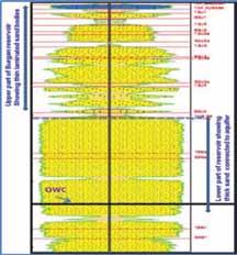
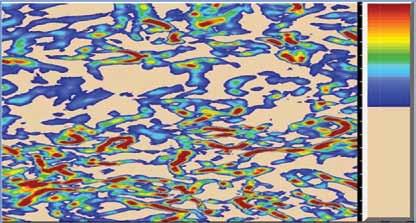
Figure 3 : Seismic coherency map showing fault networks and the intensity of Faulting and fracturing reduces from red color to blue color
Figure 4 : Well performance of conventional vertical and horizontal wells
Figure 5 : Technology Selection Workflow
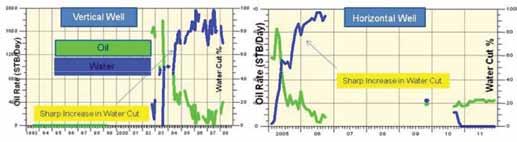
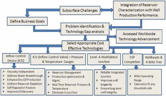
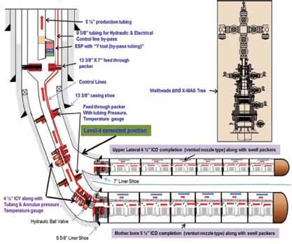
Figure 6 : Smart Multilateral Well Architecture
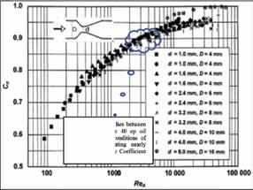
Figure 7 : Discharge coefficient of Venturi nozzle with given throat diameter vs. Reynolds number8 (Jitschin et.at 2004) Figure 8 : Pressure drop vs flow rate of 1.6mm venturi nozzle
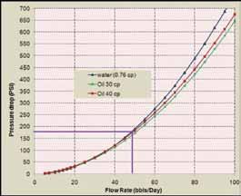
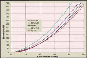
Figure 9 : Emulsion viscosity vs water cut for 40 cp oil at reservoir condition Figure 10 : Pressure drop vs flow rate of 1.6mm Venturi nozzle with emulsion at reservoir condition
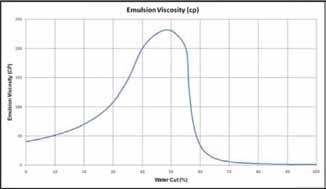
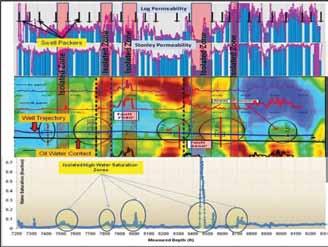
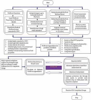
Figure 11 : Wellbore segmentation & position of isolation packers for mother bore of smart multilateral “Well A”
Figure 12 : Workflow for ICD Completion Design of Smart Level-4 Multilateral “Well A” and “Well B”
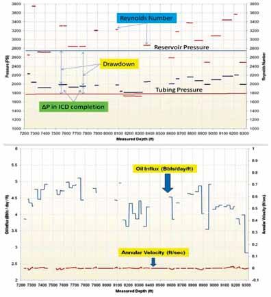
Figure 13 : Results of ICD Completion Design for mother bore of Smart Multilateral “Well A”

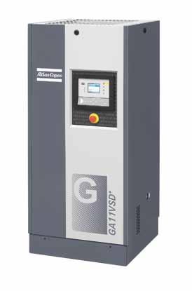
Atlas Copco introduces compact compressor technology with breakthrough energy-efficiency
For further information please contact : Emad Fawzy, Regional Business Line Manager – Industrial Air Divison Emad.fawzy@eg.atlascopco.com Mob : +2 0122 2408866

April 2013, Cairo, Egypt - On Hannover Messe2013, Atlas Copco surprised the market with a new, very compact oil-injected rotary screw compressor from 7 to 37 kW: the 7 - 37 GA VSD+ offers a leap forward in Free Air Delivery (improvements of up to 12%), and a breakthrough energy-efficiency: it requires on average 50% less energy than a comparable idling compressor. This new type of compressor offering a variable speed (frequency-controlled),will be suitable for most industries and aims to contribute significantly to the green economy needs.
Atlas Copco translated the most requested needs of its customers in this new type of compressor: better performances, with less energy consumed, & low noise levels. With the GA VSD+, a variable speed drive compressor achieves better performances even at full load than a comparable idling compressor. This innovation will enable all compressor users to switch over to variable speed drive compressors, an important step towards a more sustainable industry.
KoenLauwers, Vice-President Marketing from the Industrial Air Division comments: “In 1994, Atlas Copco pioneered the Variable Speed Drive compressor and now we have launched an innovation that will once again set the benchmark in the compressor industry. The GA VSD+ has been completely in-house developed and brings together all our expertise and know-how about energyefficient compressor technology”.
Small compressor, big ideas
Atlas Copco evaluated every part in thiscompressor: a more efficient fan, robust air intake system, eliminating all blow-off losses, and the best electronic components together with the new drive train add up to energy savings of 50% on average compared to a traditional idlingcompressor of the same type. The new GA VSD+ is another 15% more efficient than Atlas Copco’s current Variable Speed Drive compressor (the GA 737- VSD). A full feature version with an integrated dryer is available as option.
Several key components like the drive train as well as for the general design of the GA VSD+, are protected by Atlas Copco, with many patents on their way.
Available as from today
Atlas Copco also adapted its production environment to the future: the GA VSD+ is currently built in Antwerp, Belgium, on a production line that is more efficient, more standardized and that takes less space. The production of the new compressor is up and running and Atlas Copco is ready to receive customers’ orders.
Atlas Copco Equipment Egypt
Atlas Copco Equipment Egypt P.O. Box 520 El Obour market Cairo, Egypt Visitors Adress : El Obour city 1st Ind. zone- part 7 block 13024 Cairo, Egypt Phone: +202 46100337 / 8 - 46101770 /1 +202 46140800 Fax:+202 46100341
Reg. No.: 10411 Reg. Office: Nasr City www.atlascopco.com.eg
