14 minute read
NEW PRODUCTS
Next Article

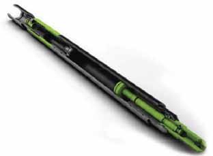
Conical-Diamond- Element Technology
Fig. (1) Smith Bits’ Stinger conical-diamond element is centrally positioned in aPDC-drill-bit cutting structure.
Smith Bits, a Schlumberger company, has introduced its Stinger conical-diamond technology. The polycrystalline-diamond element enables high point loading, to fracture rock more efficiently during drilling to increase the rate of penetration (ROP) and durability. Developed with proprietary synthetic - diamond-manufacturing technology, the conical-diamond element has anultra-thick polycrystalline -diamond layer that is significantly thicker than that of conventional polycrystallinediamond - compact (PDC) cutters. The element’s shape is optimized for strength in axial compression. When centrally positioned in a PDC-drill-bit cutting structure (Fig. 1), the new element improves performance by crushing the formation core at the borehole center, increasing drilling speed. Using the company’s IDEAS integrated-drillbit-design platform, extensive simulationswere conducted showing ROP increasesin several rock types, including shale,limestone, and sandstone. The virtualdrilling environment demonstrated thatcentral placement of this element wouldyield an ROP increase of at least 18%.In the Williston basin, an 8¾-in. PDCbit typically is used to drill the verticalhole before the curve and the lateralsection in the Bakken oil-bearing sands. In field tests, centrally placed conicaldiamond- element technology was added to the baseline vertical-section-drill-bit design. Average ROP was increased by more than 46% compared with the nextbest performance in offset wells, with a record ROP increase of 77%.
For additional information, visit www.slb.com/stinger
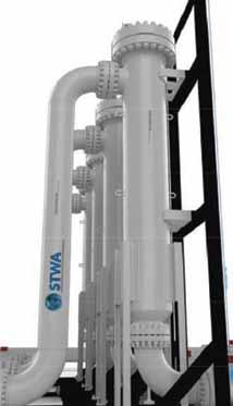
Fig. (2) STWA’s AOT 2.0 Midstream units. Fig. (2) STWA’s AOT 2.0 Midstream units.
Reducing Crude- Reducing Crude- Transmission Viscosity Transmission Viscosity
STWA’s AOT 2.0 (Fig. 2) Midstream product is an add-on system component STWA’s AOT 2.0 (Fig. 2) Midstream product is an add-on system component for pipeline pump stations. It is designed to reduce the frictional-pressure for pipeline pump stations. It is designed to reduce the frictional-pressure loss of the pipeline as the crude oil moves between pump stations along the loss of the pipeline as the crude oil moves between pump stations along the pipeline. By reducing the frictional- pressure loss in the pipeline, pumppipeline. By reducing the frictional- pressure loss in the pipeline, pumpstation operation requires less pressure to overcome the pipeline’s friction station operation requires less pressure to overcome the pipeline’s friction per mile, leading to greater energy efficiency and higher maximum flow rates per mile, leading to greater energy efficiency and higher maximum flow rates achievable within the pipeline’s pressure limits. This turnkey product uses an achievable within the pipeline’s pressure limits. This turnkey product uses an ultralow-amperage electric bath ultralow-amperage electric bath to encourage particulate-matter aggregationof the paraffin or asphalt to encourage particulate-matter aggregationof the paraffin or asphalt contentof the crude oil being transported,to reduce the viscosity of the contentof the crude oil being transported,to reduce the viscosity of the crude oil quickly and easily. The system has been tested by several entities, crude oil quickly and easily. The system has been tested by several entities, including the US Department of Energy, which reported viscosity reduction including the US Department of Energy, which reported viscosity reduction as great as 56%. Each unit has a maximum flow rate of 5,000 gal/min and as great as 56%. Each unit has a maximum flow rate of 5,000 gal/min and is designed for installation as parallel units to any pipeline flow rate, with a is designed for installation as parallel units to any pipeline flow rate, with a minimum of components and with negligible maintenance required. minimum of components and with negligible maintenance required. For additional information, visit For additional information, visit www.stwa.com.www.stwa.com.
BOP Hydrostatic Testing BOP Hydrostatic Testing
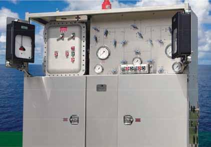
Clover Tool offers blowout-preventer Clover Tool offers blowout-preventer (BOP) hydrostatic-test units for BOP, (BOP) hydrostatic-test units for BOP, hose, manifold-valve-system, and hose, manifold-valve-system, and riserlinehydrostatic testing. These allriserlinehydrostatic testing. These allelectric test units have a small footprint, electric test units have a small footprint, are explosion proof, and are easy to are explosion proof, and are easy to customize, maintain, and operate. customize, maintain, and operate. Model CTU-20P-D24- (Fig. 3) is a dual Model CTU-20P-D24- (Fig. 3) is a dual unit that offers triple-hydrostatic-test unit that offers triple-hydrostatic-test capabilities up to 30,000 psi. During capabilities up to 30,000 psi. During critical operations, one side can be used critical operations, one side can be used as an immediate backup. When operating as an immediate backup. When operating in tandem as a single station, it can reduce in tandem as a single station, it can reduce BOP-fill/-test time by half. Operating BOP-fill/-test time by half. Operating independently, integral twin recorders independently, integral twin recorders allow separate tests at different pressures allow separate tests at different pressures simultaneously. The unit has redundant simultaneously. The unit has redundant high-pressure valving, providing washout high-pressure valving, providing washout Fig. (3) Clover Tool’s Model CTU-20P-D24- BOP test unit.Fig. (3) Clover Tool’s Model CTU-20P-D24- BOP test unit. and leakage protection. An auxiliary and leakage protection. An auxiliary fluid-supply connection provides a direct operationcontrols are accessible from either side (the chest-high console fluid-supply connection provides a direct operationcontrols are accessible from either side (the chest-high console quick-fill port (5,000 psi). Valving and is mounted for easy operator view). Filter elements are available in various quick-fill port (5,000 psi). Valving and is mounted for easy operator view). Filter elements are available in various gauges can be set for different operational micron values to accommodate customer requirements. For less-critical gauges can be set for different operational micron values to accommodate customer requirements. For less-critical modes and are switchable without operations, a 15,000-psi single-test unit, Model CTU-15P-S1, is available.modes and are switchable without operations, a 15,000-psi single-test unit, Model CTU-15P-S1, is available. opening safetyinterlockdoors. Individual opening safetyinterlockdoors. Individual For additional information, visit www.clovertool.comFor additional information, visit www.clovertool.com
HP/HT Liner-Top Packer
With standard service ratings up to 15,000 psi and 400°F, Weatherford’s SwageSet liner-top packer (Fig.4) meets International Organization for Standardization 14310 standards and is V0 qualified, demonstrating its capability to withstand combined loading conditions while maintaining seal integrity. In high-pressure/ high-temperature (HP/HT) environments, this packer increases reliability with a patentpending seal assembly that is swaged to the host casing.
Fig. (4)Weatherford’s SwageSet liner-top packer. Run as part of a liner-hanger assembly, the packer element forms a permanent, antiextrusion seal between the liner outside wall and host-casing inside wall. The seal is formed by transferring set-down weight through the polished- bore receptacle and into the integral swage, firmly sealing the packer element against the host-casing inside wall. Setting force is permanently locked into the element with integral bodylock rings. The packer’s seal system consists of ridge-shaped elastomers bonded to an expandable-metal ring and is less susceptible to swabbing off than conventional, all-elastomer elements when running in the hole or circulating at high flow rates during well-cleanup or cementing operations. The packer serves as a positivehigh-performance barrier at the linertop, preventing gas migration and isolatingannular pressures. For additional information, visit www.Weatherford.com/linersystems
Oilfield-Data Management
Senergy Software has released Version 3.8 of its Oilfield Data Manager (ODM) software suite, with significant changes, particularly in the user interface. This version includes Analysis Sticks features and enhancements to the reservoirperformance- module 3D Viewer. The geological tools enable storing, integrating, interpreting, and presenting many kinds of well-based data. The software enables incorporating and visualizing many forms of data, with the objective of using all available information to make an informed interpretation of the subsurface. The reservoir-performance module 3D Viewer makes time-based data viewable in 3D and allows the user to roll time back and forth to examine dynamic behavior. A new method for handling core shifts, which can be associated with discrete and curve data, enables the core shift to be applied automatically wherever these data are displayed such as within charts, maps, and crossplots. A new Heatmaps chart item can be used to display any numeric data, such as discrete sample data or log-curve data. A color gradient is used to represent numerical variation across selected data types for a particular well. A new Dictionary Summary provides a powerful tool for managing dictionaries within the suite. For additional information, visit www.senergyworld.com.
Formation - Damage Removal
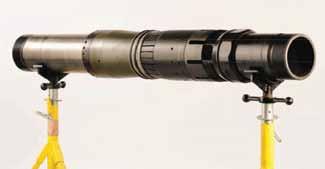
Peak Well Systems added the SIM FloWell(Fig. 5) to its SIM System well-remediation and flow-control tools. The new tool is a slick line-set remedial technology that is capable of removing formation damage within selected downhole zones to improve Fig.(5)Peak Well Systems’ productivity. SIM FloWell tool. This system improves well productivity by removing certain types of formation damage (e.g., crushed zones in perforation tunnels and tenacious filter cake and scale) in oil and gas wells that were wire line perforated. The condition of the nearwellbore region is critical in producing hydrocarbons, and the perforating process is a major contributor to skin damage. The severe compressive force of perforating can reduce the permeability of the surrounding rock, which in turn reduces productivity. Used in conjunction with the company’s SIM Plug System to provide selective isolation of the zone to be treated, the treating tool induces a sudden pressure drawdown in the wellbore, causing a surge of fluid inflow from the reservoir to reduce the skin damage. Because the tool is run, set, and retrieved on slick line it offers a low-risk intervention to clean up wellbore damage while conducting routine slickline operations. For additional information, visit www.peakwellsystems.com
Basic information on oil shale, oil shale resources, and recovery of oil from oil shale.

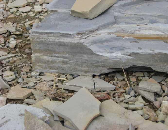
What Is Oil Shale?
The term oil shale generally refers to any sedimentary rock that contains solid bituminous materials (called kerogen) that are released as petroleum-like liquids when the rock is heated in the chemical process of pyrolysis. Oil shale was formed millions of years ago by deposition of silt and organic debris on lake beds and sea bottoms. Over long periods of time, heat and pressure transformed the materials into oil shale in a process similar to the process that forms oil; however, the heat and pressure were not as great. Oil shale generally contains enough oil that it will burn without any additional processing, and it is known as «the rock that burns». Oil shale can be mined and processed to generate oil similar to oil pumped from conventional oil wells; however, extracting oil from oil shale is more complex than conventional oil recovery and currently is more expensive. The oil substances in oil shale are solid and cannot be pumped directly out of the ground. The oil shale must first be mined and then heated to a high temperature (a process called retorting); the resultant liquid must then be separated and collected. An alternative but currently experimental process referred to as in situ retorting involves heating the oil shale while it is still underground, and then pumping the resulting liquid to the surface.
Oil Shale Resources
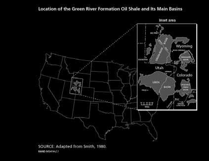
Location of the Green River Formation Oil Shale and Its Main Basins
While oil shale is found in many places worldwide, by far the largest deposits in the world are found in the United States in the Green River Formation, which covers portions of Colorado, Utah, and Wyoming. Estimates of the oil resource in place within the Green River Formation range from 1.2 to 1.8 trillion barrels. Not all resources in place are recoverable; however, even a moderate estimate of 800 billion barrels of recoverable oil from oil shale in the Green River Formation is three times greater than the proven oil reserves of Saudi Arabia. Present U.S. demand for petroleum products is about 20 million barrels per day. If oil shale could be used to meet a quarter of that demand, the estimated 800 billion barrels of recoverable oil from the Green River Formation would last for more than 400 years1. More than 70% of the total oil shale acreage in the Green River Formation, including the richest and thickest oil shale deposits, is under federally owned and managed lands. Thus, the federal government directly controls access to the most commercially attractive portions of the oil shale resource base.
The Oil Shale Industry
While oil shale has been used as fuel and as a source of oil in small quantities for many years, few countries currently produce oil from oil shale on a significant commercial level. Many countries do not have significant oil shale resources, but in those countries that do have significant oil shale resources, the oil shale industry has not developed because historically, the cost of oil derived from oil shale has been significantly higher than conventional pumped oil. The lack of commercial viability of oil shale-derived oil has in turn inhibited the development of better technologies that might reduce its cost.
Relatively high prices for conventional oil in the 1970s and 1980s stimulated interest and some development of better oil shale technology, but oil prices eventually fell, and major research and development activities largely ceased. More recently, prices for crude oil have again risen to levels that may make oil shale-based oil production commercially viable, and both governments and industry are interested in pursuing the development of oil shale as an alternative to conventional oil.
Oil Shale Mining and Processing
Oil shale can be mined using one of two methods: underground mining using the room-and-pillar method or surface mining. Major Process Steps in Mining and Surface Retorting After mining, the oil shale is transported to a facility for retorting, a heating process that Mining and crushing Retorting Oil upgrading Oil to refinery separates the oil fractions of oil shale from the mineral fraction.. The vessel in which retorting takes place is known as a retort. After retorting, the oil must be upgraded Spent shale by further processing before it can be sent disposal on - site Reclamation to a refinery, and the spent shale must be disposed of. Spent shale may be disposed of in surface impoundments, or as fill in graded areas; it may also be disposed of in previously mined areas. Eventually, the mined land is reclaimed. Both mining and processing of oil shale involve a variety of environmental impacts, such as global warming and greenhouse gas emissions, disturbance of mined land, disposal of spent shale, use of water resources, and impacts on air and water quality. The development of a commercial oil shale industry in the United States would also have significant social and economic impacts on local communities. Other impediments to development of the oil shale industry in the United States include the relatively high cost of producing oil from oil shale (currently greater than $60 per barrel), and the lack of regulations to lease oil shale.
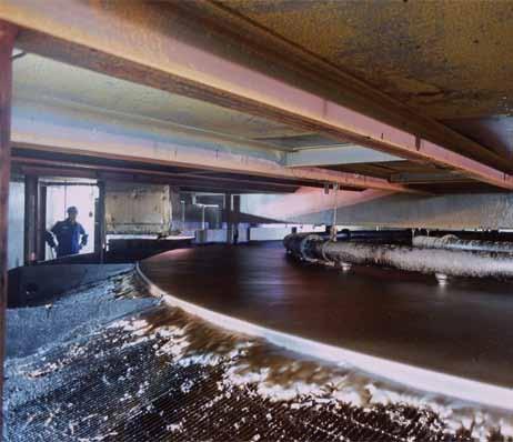
Surface Retorting
While current technologies are adequate for oil shale mining, the technology for surface retorting has not been successfully applied at a commercially viable level in the United States, although technical viability has been demonstrated. Further development and testing of surface retorting technology is needed before the method is likely to succeed on a commercial scale.
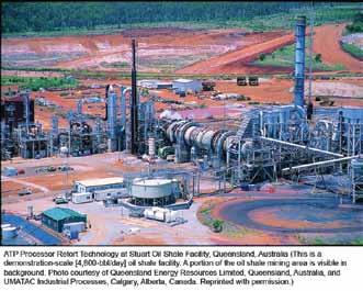
Stuart Oil Shale Facility, Queensland, Australia Surface Retort
In Situ Retorting
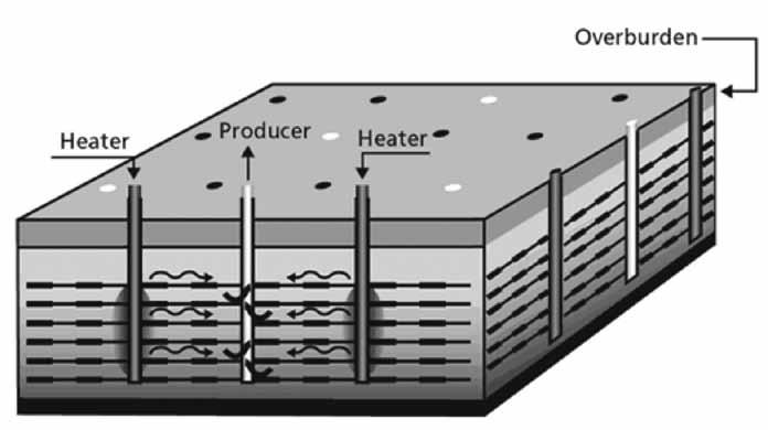
Shell Oil is currently developing an in situ conversion process (ICP). The process involves heating underground oil shale, using electric heaters placed in deep vertical holes drilled through a section of oil shale. The volume of oil shale is heated over a period of two to three years, until it reaches 650–700 °F, at which point oil is released from the shale. The released product is gathered in collection wells positioned within the heated zone.
Shells current plan involves use of ground-freezing technology to establish an underground barrier called a «freeze wall» around the perimeter of the extraction zone. The freeze wall is created by pumping refrigerated fluid through a series of wells drilled around the extraction zone. The freeze wall prevents groundwater from entering the extraction zone, and keeps hydrocarbons and other products generated by the in-situ retorting from leaving the project perimeter. Shell’s process is currently unproven at a commercial scale, but is regarded by the U.S. Department of Energy as a very promising technology. Confirmation of the technical feasibility of the concept, however, hinges on the resolution of two major technical issues: controlling groundwater during production and preventing subsurface environmental problems, including groundwater impacts.1 Both mining and processing of oil shale involve a variety of environmental impacts, such as global warming and greenhouse gas emissions, disturbance of mined land; impacts on wildlife and air and water quality. The development of a commercial oil shale industry in the U.S. would also have significant social and economic impacts on local communities. Of special concern in the relatively arid western United States is the large amount of water required for oil shale processing; currently, oil shale extraction and processing require several barrels of water for each barrel of oil produced, though some of the water can be recycled.
Major Process Steps in Thermally Conductive In-Situ Conversion
Drilling and site preparation Heating and production
Oil to refinery
Postproduction clean-up
The Shell In-Situ Coversion Process
1 RAND Corporation Oil Shale Development in the United States Prospects and Policy Issues. J. T. Bartis, T. LaTourrette, L. Dixon, D.J. Peterson, and G. Cecchine, MG-414-NETL