18 minute read
Impact of application of occupational health and safety standards in petroleum industries of west sector of Alexandria

Next Article

Figure 1. Total injuries in petroleum companies of west Alexandria sector from 2010 to 2014. Figure 2. Classification of minor injuries according to body part affected.

Figure 3. Frequency of accident-related causes in the target industrial sector.
Table 1. Total occupational injuries in petroleum companies of west Alexandria sector from 2010 to 2014.
Year 2010 2011 2012 2013 2014 Total Major accident with death 1 (5%) 1 (5%) - - 1 (5%) 3 (3%) Major accident with amputation 1 (5%) 1 (5%) - 1 (5%) 3 (15%) 6 (6%) Minor injuries 19 (90%) 17 (90%) 19 (100%) 21 (95%) 16 (80%) 92 (91%) Total injuries 21 (100%) 19 (100%) 19 (100%) 22 (100%) 20 (100%) 101 (100%)
Table 2. Classification of minor injuries according to body part affected.
Year Injured organ Head Upper limbs Lower limbs Total injuries 2010 2011 2012 2013 2014 Total
2 (10%) 5 (29.4%) 5 (26%) 8 (38%) 2 (12.5%) 22 (24%) 6 (32%) 5 (29.4%) 7 (37%) 3 (14%) 9 (56.25%) 30 (33%) 11 (58%) 7 (41.2%) 7 (37%) 10 (48%) 5 (31.25%) 40 (43%) 19 (100%) 17 (100%) 19 (100%) 21 (100%) 16 (100%) 92 (100%)
Table 3. Accidents’ crude rate, frequency and severity rates in west Alexandria petroleum sector from 2010 to 2014.
C.R.
2010 2011 2012 2013 2014 25.62 20.81 8.67 32.43 21.01
F.R.
2.98 2.01 1.19 3.24 2.12
S.R.
277.72 1448.88 51.07 65.46 228.08 C.R = Crude Ratio ( injured Workers/10000 workers ) F.R= Frequency Rate ( Injury/million hours) S.R=Severity Rate (Days lost/million hours)
Technology Applications
Successful Application of A New Inertial Steering Mode of Pointthe-Bit RSS in Middle East Oilfield
By
F. Li, M. Balka, and A. Al-Ghazzawi, Schlumberger
Abstract
In the past two decades, the point-the-bit rotary steerable system (RSS) has been widely used for highprofile directional drilling jobs in challenging environments, which require accurate directional control. A new inertial steering mode of the point-the-bit RSS was developed by using accelerometers and a rate gyroscope sensor to achieve toolface control in environments, where magnetometers cannot be used for steering. This inertial steering mode effectively expands the operational envelope of point-the-bit RSS by improving its steering ability when magnetic interference, such as drilling out of whipstock window and close to offset wells or ferrous formations, is present or within a Zone of Exclusion (ZOE). Furthermore, the new steering mode can be used as a redundancy scheme in circumstance during magnetometer failures. Through close collaboration between Research and Development (R&D) and field operation, the inertial steering mode of the point-the-bit RSS has been successfully applied in four wells in Middle East oilfield. In the first well, the new steering mode was used to kick off two 8 3 / 8» hole sections after setting whipstocks in near vertical wells and it completed the kick-offs in desired directions with accurate toolface control in a high magnetic noise environment. In the second well, the new steering mode was used to exit the casing and drill to TD by using a whipstock. In the third and fourth wells, 12 ¼» hole sections passing through the ZOE were successfully drilled according to the well plan. The application of the new steering mode in these wells saved extra BHA trips, which would have been required if without this new steering mode. The successful application of the new steering mode in the Middle East oilfield has proven its technical advantages and business benefits.
Introduction
Oilfields in the Middle East presents various challenges in drilling and completion. Directional trajectory control is one of the challenges, which is mainly caused by • directional drilling in congested platforms, • deep sidetracks from vertical cased hole, • window exits from already drilled wells, • and planned trajectories passing through the ZOE. Historically, steerable motors with MWD tools were used to drill wells from platforms and whipstocks were sometimes used for sidetracking or multilateral drilling, which, however, required extra BHA trips. In the latter case, drilling performance was also compromised when deep near-vertical wells were kicked off due to inaccurate toolface control in magnetic interference environments. To achieve better toolface control, the point-the-bit rotary steerable system has been implemented particularly in the situations where hydraulic limitation is present because of high mud weight in deep gas drilling environment or in soft formations where other technologies have difficulties in achieving planned trajectories. The point-the-bit rotary steerable system uses a counter rotating methodology for toolface control (Schaaf et al. 2000). As Fig. 1 shows, the axis of the bit shaft is offset by a mandrel, which is then controlled geostationarily by a counter rotating motor during collar rotation. The tool controls the toolface orientation of the bit shaft geostationarily by driving the motor in the opposite direction to collar rotation at the same rotation speed. To change toolface, motor velocity is slightly
adjusted to change the toolface position of the mandrel and point the bit in the desired direction. For toolface control, the control system requires two parameters, i.e. the rotation rate of the collar and the toolface orientation of the bit shaft. An angular position sensor and magnetometers in a direction and inclination (D&I) sensor package measure these two parameters. As a strap-down RSS tool, it primarily uses the magnetic field to perform toolface control. In the cases that magnetic field measurement is interfered, such as inside casing or during the tool was used with whipstocks or when magnetic field measurement does not have enough signal strength, known as Zone of Exclusion (ZOE), the RSS tool cannot control its toolface. As a result, the application of the RSS tool requires caution during well planning to avoid the trajectories passing through ZOE, which, however, limits its operation envelope. To expand the tool,s operation envelope, a new steering mode, the inertial steering mode, has been developed to use inertial sensors for toolface and trajectory control.
Design of New Inertial Steering Mode
The new inertial steering mode utilizes accelerometers and a rate gyro. While the accelerometers remain part of the existing D&I sensor package, the rate gyro sensor is a new addition to the tool. In the laboratory, the rate gyro sensor was qualified with the measurement ranging up to 350RPM; a real-time calibration algorithm was developed in downhole firmware to tackle the inherent drifts of the sensors; the sensor performance and calibration were verified and validated. Since downhole shock and vibration are likely to distort accelerometer and rate gyro measurement, effective filtering algorithm has to be developed to eliminate undesired noise. In the new steering mode, downhole high-frequency data sets, which included lateral shocks and collar rotation speed from the gyro, were analyzed to understand the frequency spectrum for low-pass filter design. The plots in Fig. 2 show one data set used for the analysis. Fig. 3 shows the control diagram of the new inertial steering mode. The rate gyro is used to estimate the collar rotation speed. The lateral accelerometers together with the angular position sensor are used to compute gravity toolface. In the design, a low-pass filter is employed to realize stable toolface control. After the new inertial steering mode was designed, a series of laboratory tests were conducted on a rotating machine, which was used to validate sensor computation and toolface control. Fig.4 shows four signal traces during a rotation test. TF is the RSS toolface; RT_Mode_Bit11 is the bit 11 of a real-time data point for the indication of the steering modes with 0 indicating the magnetic steering mode and 1 indicating the inertial steering mode; gyro is the rotation speed measured by the rate gyro sensor and magvel is the rotation speed measured by the magnetometers. The test was started at 09:27 Jan. 01 using the magnetic steering mode. The steering mode was switched to the inertial steering mode at 09:35. The toolface control was smoothly indexed from 0 to 360 deg as designed. Slight discrepancy between MagVel and Gyro were noted, which was caused by the magnetic field interference from metal and electrical surroundings. To facilitate seamless integration of this new steering mode with oilfield operation, a downlink has been implemented in the RSS to toggle between the inertial and magnetic steering modes. The downlink does not require to change any drilling parameters during toggling between two modes. The engaged operation mode can be seen in real-time surface display. As an operation guideline, the RSS is tripped in with the inertial steering mode to ensure the steerability inside casing or with whipstock. If desired, the inertial steering mode can be dis-engaged to use magnetic field measurement for steering. When inclination is lower than 2 degree, the toolface computed from magnetometers will be utilized due to diminished gravity toolfaces.
Benefits of the New Inertial Steering Mode
The new inertial steering mode contributes to an enhanced steering ability of the RSS when the tool is within a blind zone or the ZOE. As a result, the RSS operation envelope is increased by the inertial steering mode based on the following enhancements: Ó removal of the ZOE requirement, Ó better toolface control out of casing and the zone close to casing shoe, Ó better toolface control when drilled well is close to offset wells, which are likely to introduce magnetic interference, Ó better toolface control while drilling out of whipstock, Ó and the provision of a RPM sensor redundancy in the RSS tool.
Field Run Results
This section presents four successful field runs with the new steering mode in the RSS. Technical challenges existed in all the wells where magnetic interference was present or ZOE was passed through well paths.
Well-A
The first well was drilled from an offshore platform with the objective of drilling and completing as a dual producer. The original borehole had multiple casing and completion strings
and an exit was planned from 13 3 / 8» casing at 25 deg inclination in a 12 ¼» hole. Significant magnetic interference was expected from the casing and completion accessories; the interference could saturate the magnetometers of the point-thebit RSS and thus could result in steering inability The option of using steering motors for drilling the exit had been proposed and evaluated, which, however, would have require a second run after the window exited to reach TD. The new inertial steering of the RSS was then put forward as a feasible solution and finally was adopted for the job. Fig. 5 shows the toolface control performance of the RSS tools in downhole. From 23:30, April 28th to 1:30, April 29th, the magnetic field measurement traces of RSS_Hy and RSS_Hz were saturated at over 75,000nT. The RSS_Magvel measured by magnetometers showed the erratic toolface measurement during this time, whilst the RSS_TF measured by inertial sensors was used to control the toolface matching the desired toolface RSS_TF_Des trace. The data show that the inertial steering mode was able to control the toolface of the RSS under the situation of significant magnetic field interference. The well was steered away from the mother bore in the planned direction followed by building inclination and landing the well. The new steering mode allowed the window exit and reached the TD with a signal run with the point-the-bit RSS. The technical solution saved an extra run for client with significant financial benefits.
Well- B
In this nearly vertical well, the well plan was to set a whipstock in 9 5 / 8» casing and kick off in deep well in 8 3 / 8» hole. Previously, similar wells in the Middle East were drilled with motors and rock bits after setting Whipstocks. The disadvantages are listed below. Ó In the same BHA, a single shot gyro for toolface orientation had to be run for toolface orientation purpose; Ó It requires an extra BHA trip. In case that a PDC bit was used to save the trip and the well was drilled to TD with motors, the lower ROP were recorded, and the inability of kicking off from a planned azimuth were identified due to the unavailability of the real-time gravity/magnetic toolface. Aftert detailed planning and risk assessement in coordination with R&D, operation support center, drilling engineers and directional drillers, a comprehensive field run plan was developed including the use of the new steering mode of the RSS. By using the inertial steering mode of the RSS, this well was kicked off successfully in the planned direction. The real-time data show the actual toolface from the inertial gyro matched the desired toolface. Fig. 6 shows the toolface control performance of the RSS tools in this job. For most of the time, magnetic field measurement was interfered; the RSS_TF measured by inertial sensors was used to control the toolface matching the desired toolface RSS_TF_Des trace. The data showed that the inertial steering mode was able to control the toolface of the RSS under the situation of significant magnetic field interference. The data also show some variation on the RSS_ TF when the tool was steering and this was attributed to the near vertical direction.
Well- C
Well-C has the profile of building from low inclination in the NE direction, holding for 1000m, turning from NE to NW direction and then building the inclination above 60 deg at the TD of the section. The challenge for the run was the wellpath passing through the ZOE, in which the magnetic steering mode could not steer. Therefore, the new inertial steering mode was selected for the run. Fig. 7 shows overall toolface control performance of the RSS tools in downhole for the Well-C. Between June 5th and June 8th, the magnetic field measurement traces of RSS_Hy and RSS_Hz were as low as 10,000nT. The RSS_Magvel measured by magnetometers shows the erractic toolface measurement during this time, whilst the RSS_TF measured by inertial sensors was used to control the toolface matching the desired toolface RSS_TF_Des trace. The data showed that the inertial steering mode was effective to control the toolface of the RSS under the situation of the ZOE.
Well- D
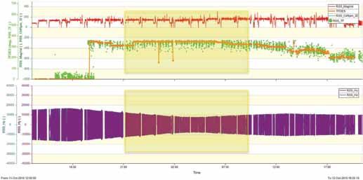
Well-D has a 2-D profile towards the NNE direction with the focused on building the inclination. The challenge of the run was the wellpath passing through the ZOE, in which the magnetic steering mode could not steer. As a result, the new inertial steering mode was selected for the run. Fig. 8 shows overall toolface control performance of the RSS tools in downhole for the Well-D. Between 21:00 to 9:00, Oct.15, 2015, the magnetic field measurement traces of RSS_Hy and RSS_Hz were as low as 8,000nT. The RSS_ Magvel measured by magnetometers showed the erratic toolface measurement during this time, whilst the RSS_TF measured by inertial sensors was used to control the toolface matching the desired toolface RSS_TF_Des trace. The data show that the inertial steering mode was effective to control the toolface of the RSS under the situation of the ZOE.
Conclusion
The new inertial steering mode was developed for the pointthe-bit RSS tool and the technology was deployed in Middle
www.wilhelmsen.com
Email: wss.alexandria.operations@wilhelmsen.com Fax: +203 48 69 555 Tel: +203 48 43 510 Sultan Hussein, Alex andria Head Office: 9 Hussein Hassab & Bani El Abbasi, El Zaher Building (2),
Barwil Egytrans Shipping Agencies S.A.E. Wilhelmsen Ships Service
optimized and your cargo delivered without delays. global port intelligence ensures your port turnarounds are As your partner in port, our specialized cargo knowledge and your ships on the move. As an extension of your team, we keep your port stays short and we understand your business intuitively and every port intimately. With 75,000 port calls handled annually in 2,200 ports globally,
Wilhelmsen Ships Agency Simplify your port calls with

East Field. Four successful field runs have been successfully completed and the tool performed well in all the four sections drilled with exposure to different directional profiles. a.Window exit from 13 3 / 8» casing and drill ahead in 12 ¼» hole; b.Window exist across whipstock from deep near vertical well in 8 3 / 8» hole; c.Two runs in 12 ¼» hole with inertial toolface control across ZOE. The new inertial steering mode of the RSS tool is time- and costeffective, as it reduces the number of BHA runs and reduces the single shot gyro runs for toolface orientation. The four successful runs prove that the new inertial steering mode has increased the operation envelope of the Point-the-bit RSS tool.
REFERENCE
1. Schaaf, S.; Mallar, C. R.; and Pafitis, D. «Point-the-bit Rotary Steerable System: Theory and Field Results,» SPE Paper 63247, presented at the 2000
SPE Annual Technical Conference and Exhibition held in Dallas, Texas, 1 - 4 October 2000
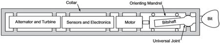
Figure 1—Block diagram of the Point-the-bit RSS system
Figure 2—Lateral shock characterization; top plot – radial shock waveform; upper middle plot – frequency spectrum of the radial accelerometers over whole frequency range; lower middle - frequency spectrum of the radial accelerometers to 20 Hz without DC component; bottom plot – collar rotation speed by the gyro
Figure 3—The control diagram of the new inertial steering mode of the RSS
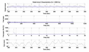
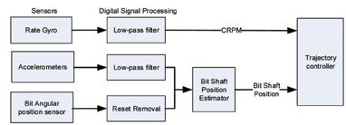
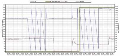
Figure 4—Toolface control in magnetic and inertial steering mode; TF – Toolface; RT_Mode_Bit11 – indication of magnetic steering mode (0) and innerial steering mode (1); gyro – rotation speed by rate gyro sensor; Magvel - rotation speed by magnetometers
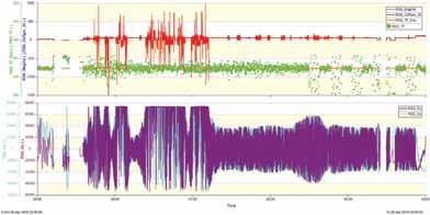
Figure 5—RSS toolface control performance in Well-A (upper plot is the toolface and RPM traces; lower plot is the lateral magnetic field measurement) in the Well-A
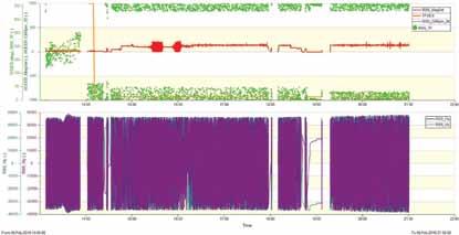
Figure 6—RSS toolface control performance (upper plot is the toolface and RPM traces; lower plot is the lateral magnetic field measurement) in the Well-B
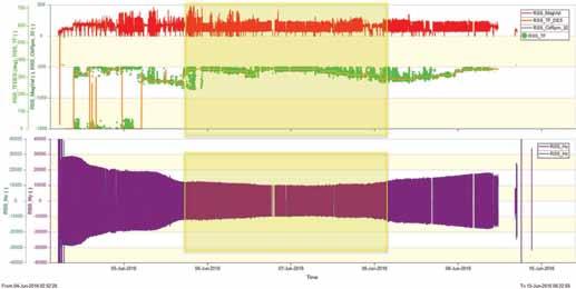
Figure 7—RSS toolface control performance (upper plot is the toolface and RPM traces; lower plot is the lateral magnetic field measurement) in the Well-C
Figure 8—RSS toolface control performance (upper plot is the toolface and RPM traces; lower plot is the lateral magnetic field measurement) in the Well-D


MOC 2019

MOC 2019 IS CELEBRATIN 20 YEARS OF SUCCESS
The 10th edition of MOC 2019 – Mediterranean Offshore Conference and Exhibition, the official event of the Egyptian Petroleum Sector, will take place in Alexandria, EGYPT from 14 to 16 October 2019.
MOC is Egypt’s premier energy event supporting Egypt’ s oil and gas industry with a history going back to 2000. Organized by the Egyptian Petroleum Sector, MOC is the most important international energy meeting on the southern shore of the Mediterranean region. MOC is a sister event with OMC – Offshore Mediterranean Conference and Exhibition which takes place in Ravenna, ITALY and they both keep focusing E&P companies, contractors, service companies and suppliers to the Mediterranean Offshore Oil&Gas sector. The companies keep recognising in MOC and OMC a defining meeting points where to discuss about the major Oil&Gas issues and where industry comes together to network, learn and grow.
The MOC 2019 conference revolves around EGYPT: Connecting the two shores of the Mediterra-
nean.
The Oil&Gas industry has gained significant attention as Egypt became the 2nd wealthiest country in Africa, thanks mainly to the recent discoveries and the great potentials which are arising from the business opportunities in Egypt.
The three days of Conference and Exhibition will bring together up to 500 industry stakeholders; thought leaders, policy makers, business leaders and key decision makers within the public and private sectors.
MOC is where you will meet your peers to discuss Mediterranean energy Business and where you will meet your new perspective partners, customers and suppliers. In the industry network with 1000s of professionals you will have the opportunity to show your finest to your potential customers and to solidify your reputation as a key supplier to the industry.
The MOC Organising Team take immense pleasure in inviting you to attend and celebrate with us 20 years of continuous success.
Registration for MOC 2019 IS NOW OPEN
Please contact us for further information and to book your space:
exhibition@moc-egypt.com or +20 102 6229655 www.moc-egypt.com
Lube Tips
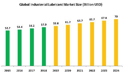
Lube-Tips is a unique informational resource selected to give petroleum today readers an insider’s grasp of lubrication and lubricants. Each issue, offers tips and facts intended to provide mind-opening insights and take the mystery out of machinery lubrication & this issue it was selected to shed more light on the global industry facts in a generic way.

The history of industrial lubricating oils
The history of industrial lubricating oils began as soon as man discovered that reduced friction meant greater efficiency. There are many different types of industrial lubricating oil and each oil has been developed over time to serve a different purpose. Early hand or horse-powered machinery was often made from very heavy, cast metal components. Thick, treacle-like industrial

lubricating oils were developed to reduce friction between these heavy surfaces. Early engineers were quick to recognize that proper use of the correct industrial lubricant oil ensured smooth running machinery and longer component life. The steam engine signaled a new era in the history of industrial lubricant oils as it created challenges that had never been seen before. Steam engines could run faster and for longer than any previous machine but this produced a brand new range of engineering challenges. Possibly the biggest challenge faced by early engineers was to reduce the amount of friction generated by their machines and at the same time, to reduce the heat generated by that friction. Excessive heat causes metal to expand and expensive machinery to stop working. It was more cost effective to develop effective industrial lubricating oils than keep replacing burned out bearings! As machinery became faster and more complex and components