10 minute read
Protection against the elements

Next Article

to shore. Protecting these critical power cables from excessive movement or bending that could potentially cause fatigue damage in this demanding offshore environment is of utmost importance. High voltage power cables are both expensive to install and replace, with replacement costs in the region of millions of Euros, even before factoring in wind turbine downtime and the huge loss of revenue from reduced output.
Figure 1. Monopile with scour protection.
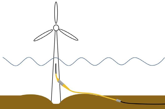
Figure 2. Monopile with scour pit.
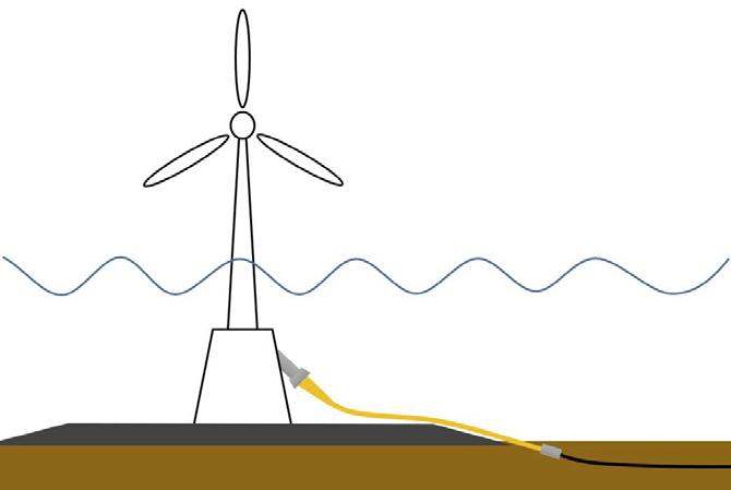
Figure 3. J tube with scour protection.
Experience gathered from fixed wind technologies, along with the drive of floating wind into increasingly dynamic environments, has increased focus and highlighted the importance of cable protection. Careful consideration is essential in order to maintain the integrity of the power cables for the life of the field.
Why is cable bend protection needed?
Whilst numerous kilometres of power cables are installed on every wind farm, they are vulnerable to damage at a number of critical locations – one of the key ones being the connection points into the turbine or substation foundation.
With fixed wind turbine structures, the cable is typically protected through trenching and burial for the majority of its length, with exposure in the approach towards connection points in consideration of the connection arrangement and installation methodology. In some cases, the burial point can typically be as far as 30 m from its connection point, and can be even longer if there has been significant seabed scour around the foundation of the structure. In this exposed area, the cable becomes subject to loads and motion from the surrounding sea conditions.
With floating wind platforms, the cable is exposed over longer lengths in the water column between the seabed and the floating foundation of the turbine, and will potentially experience even greater levels of dynamic load and motion.
In the exposed areas described, the dynamic forces on the cable produce cyclical motions relative to the foundation. These motions and loads concentrate towards the rigid connection point where the cable experiences a sharp transition in stiffness. As the cables have relatively low stiffness, they are highly susceptible to both over-bending and fatigue damage at this point. To mitigate this, bend protection is needed.
Cable bend protection: key applications
The critical locations where dynamic bend protection should be applied to power cables are illustrated in this article.
Fixed offshore wind:
> Monopile with scour protection: inside and outside monopile (Figure 1). > Monopile with scour pit: inside and outside monopile (Figure 2). > J tube with scour protection (Figure 3). > J tube with scour pit (Figure 5).
Floating offshore wind:
> Topside floating foundation connection (Figure 6). > Tether clamp transitions (dependent on the level of motion at the tether clamp location) (Figure 6).
Cable bend protection analysis and design
A cable’s bend protection requirements can be unique to each application. In order to analyse the application and develop a bend protection device that is fit for purpose, the following parameters are critical design considerations:
Met ocean data: Detailed information is required in order to determine the design envelope of conditions the cable will be subjected to across all sea states and temperatures. Data analysis will determine the requirements in terms of load ranges, motions, curvatures, and corresponding number of cycles acting on the cable, within the vicinity of the connection point.
Temperature: The mechanical performance characteristics of polymer materials used in cable and bend protection device construction can vary with temperature. Therefore, it is important to ascertain the minimum and maximum temperature ranges of the surrounding environment along with the cable operating temperatures, to ensure the mechanical performance variation can be accommodated within the analysis and design.
Cable dimensions and weight: These cable parameters determine the nature of reaction against the wave and current dynamic forces, and therefore influence the level of loads and motion on the cable. Outer diameter is also a key consideration in the dimensional fit of any bend protection device.
Cable mechanical parameters: The cable’s bend stiffness and minimum bend radius (MBR) characteristics are essential for accurate modelling of cable dynamic motions and assessment of the suitability of any proposed bend protection device. Typically, the cable manufacturer will determine and advise a storage MBR for short-term or static load applications and a larger service MBR, required to be adhered to, to avoid damage under longer term dynamic loads. Cable thermal characteristics: As the bend protection surrounds the cable it can insulate the cable and increase the cable temperature. Thermal analysis is therefore necessary to check that the cable does not exceed its allowable temperature limits. Understanding the cable’s thermal characteristics and temperatures is necessary, along with surrounding environmental information, to perform this analysis.
In order to evaluate the cable’s bend protection requirements unique to the application, a global finite element analysis (FEA) using Orcaflex modelling software or similar is performed utilising the various data sets collected. This enables the design engineer to set up a boundaryconstrained model, evaluate the loads and motions of the cable towards the connection point, and determine the impact of introducing a bend protection system. This can be an iterative design process that continues until the bend protection device can maintain the cable’s motions and curvatures within allowable design limits for all load cases. The model will analyse the cable with the bend protection device typically under the following main dynamic conditions: ultimate limit state (maximum load, low number of cycles) and fatigue limit state (normal load, high number of cycles).
Once a bend protection system is identified that satisfies dynamic performance requirements, the output from the model can be used to proceed to local mechanical design of the bend protection system and its components, and thermal analysis including the cable to verify allowable temperature limits are maintained.
Dynamic cable bend stiffeners
For dynamic bend protection applications where the cable is exposed to frequent motion, such as the applications discussed, then a bend stiffener solution is recommended to maintain cable integrity.
A bend stiffener comprises of a homogeneous elastomeric cone with geometry and material properties designed to provide a gradual and tailored transition in
stiffness from its tip to its base. This is a crucial feature as during operation
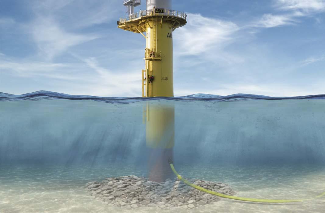
Figure 4. Trelleborg’s NjordGuard solution attached to a monopile wind turbine with scour protection.
it removes the previous sharp change in stiffness at the connection point and protects the cable from over-bending and excessive fatigue.
The bend stiffener provides continuous support to the cable at the connection point, ensuring the overall curvatures of the cable inside and adjacent to the bend stiffener are significantly reduced when under load. Therefore, for any given load cycle there is significant reduction in the stress range acting on the cable and associated fatigue.
This is a key difference in comparison to bend protection devices for static applications such as bend restrictors (vertebrae) and bellmouths. These static devices are designed to protect the cable from over-bending through, in the case of bend restrictors, interlocking vertebrae or, in relation to bellmouths, a radiused flare profile equal or greater than the MBR of the cable. Whilst these bend restrictors and bellmouths prevent infringement of the cable MBR, they do not provide the gradual stiffness transition or continued cable support throughout the full range of cable motions. Therefore, in comparison to a bend stiffener solution, the cable remains exposed to higher stress ranges under dynamic loads, which can result in premature fatigue issues.
Trelleborg utilises dynamic bend stiffeners in the fixed wind applications as part of its NjordGuard Cable Protection System and on floating wind applications, often mated to a diverless bend stiffener connector for quick installation.
As a bend stiffener needs to provide dynamic cable protection for the life of the field, it is important that the product itself is designed to survive the rigors of both installation and service. Careful consideration needs to be particularly paid to: > Elastomeric materials selection and qualification: The elastomeric materials selected for the flexible cone naturally are a core part of the bend stiffener functionality. In order to use them effectively it is important that their mechanical, fatigue, and ageing performance characteristics are mapped and qualified over a range of temperatures before applying them into the design of the bend stiffener product. Trelleborg typically recommends working to the established oil and gas industry standard, API 17L.
Insert design: The insert at the base of the stiffener plays the crucial role of effectively transferring the loads from the cable and conical bend stiffener section into the adjacent structure. A combination of 3D FEA modelling of the steel insert and elastomer interface and classical calculations is used to determine a suitable design to withstand maximum design and fatigue loads.
Verification testing: It is important that the design is verified through theoretical FEA models and full-scale dynamic and static load testing.
Summary
Utilising a bend stiffener over other bend protection solutions can provide the most appropriate design solution for cable connection points on fixed and floating offshore wind structures where the cable is exposed to dynamic environmental conditions, ensuring continuous protection of the cable from over-bending and fatigue.
As applications are often unique in their requirements, careful analysis of the parameters is necessary in order to identify the most appropriate bend protection solution. Selecting the right bend protection solution for both the specific wind turbine and the environment will help prevent cable damage and subsequently reduce operations and maintenance costs by maximising the life of the cable, removing the need to prematurely replace or repair cables in service.
By protecting the wind turbine dynamic power cable at its most vulnerable points, the integrity can be maintained for the entire design life expectancy of the field and beyond, supporting the renewables industry with wind turbine expansion into deepwater environments in the pursuit for cleaner energy sources and reducing the effect of climate change.
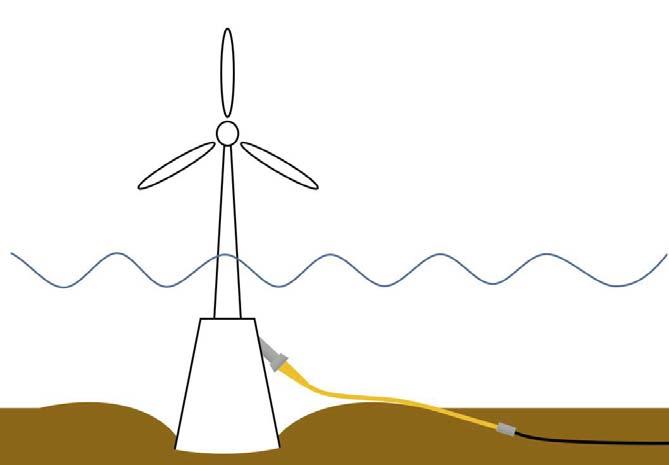
Figure 5. J tube with scour pit.
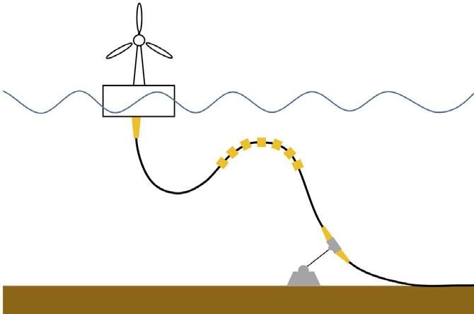
Figure 6. Topside floating foundation connection and tether clamp transitions.
Over the last decade, the realisation of digital twin technology has made it possible to move away from the arena of best-guess simulations that lacked the power to provide the required accuracy of output while still providing enough flexibility in input modalities. In other words, a simulation might be stable with one set of inputs, but change one parameter, and your simulation often crashed and burned. Now, however, there is finally the computing power to begin to sufficiently model outcomes and processes using techniques such as Bayesian statistics (developed by Thomas Bayes in a paper from 1763) that, even five years ago, still ran


multi-core processors ragged. The use of such processes have allowed us to begin to forge proper digital twins that allow us to model the hypothetical, ‘What if?’ driven questions that take us beyond mere simulations. These are the sorts of questions that must be asked if a digital twin is to function adequately as a decision support platform.
Unfortunately, for a number of reasons, the offshore wind industry has been slow to take up digital twin technology, and some of the scepticism is understandable. Questions around how much twinning is too much, and concerns about the legal liabilities behind digital twin output if it, for example, drives a
Bill Ballew, James Fisher Asset Information Services (AIS), UK, considers the application of digital twin technology in the offshore wind industry.