Coding Modbus TCP/IP for Arduino

Example projects with Node-RED, MQTT, WinCC SCADA, Blynk, and ThingSpeak booksbooks


Example projects with Node-RED, MQTT, WinCC SCADA, Blynk, and ThingSpeak booksbooks
Example projects with Node-RED, MQTT, WinCC SCADA, Blynk, and ThingSpeak
● Dr. Majid Pakdel● This is an Elektor Publication. Elektor is the media brand of Elektor International Media B.V. PO Box 11, NL-6114-ZG Susteren, The Netherlands Phone: +31 46 4389444
● All rights reserved. No part of this book may be reproduced in any material form, including photocopying, or storing in any medium by electronic means and whether or not transiently or incidentally to some other use of this publication, without the written permission of the copyright holder except in accordance with the provisions of the Copyright Designs and Patents Act 1988 or under the terms of a licence issued by the Copyright Licencing Agency Ltd., 90 Tottenham Court Road, London, England W1P 9HE. Applications for the copyright holder's permission to reproduce any part of the publication should be addressed to the publishers.
● Declaration
The authors and publisher have used their best efforts in ensuring the correctness of the information contained in this book. They do not assume, or hereby disclaim, any liability to any party for any loss or damage caused by errors or omissions in this book, whether such errors or omissions result from negligence, accident or any other cause.
● ISBN 978-3-89576-614-5 Print
ISBN 978-3-89576-615-2 eBook
● © Copyright 2024 Elektor International Media www.elektor.com
Prepress Production: D-Vision, Julian van den Berg
Printers: Ipskamp, Enschede, The Netherlands
Elektor is the world's leading source of essential technical information and electronics products for pro engineers, electronics designers, and the companies seeking to engage them. Each day, our international team develops and delivers high-quality content - via a variety of media channels (including magazines, video, digital media, and social media) in several languages - relating to electronics design and DIY electronics. www.elektormagazine.com
This book provides a comprehensive and detailed guide on implementing the ModbusTCP/IP protocol with Arduino development boards. Some of the information presented was derived from my personal notes taken during Emile Ackbarali’s “How to Program an Arduino as a Modbus TCP/IP Client & Server” training course on Udemy. Additionally, I have successfully established TCP/IP communication between two Arduino Uno boards.
The book also delves into the topic of Modbus TCP/IP communication in the Node-RED environment and explains the process of interfacing Modbus TCP/IP with WinCCSCADA. Also, it demonstrates how to control sensors using Ethernet and the Blynk app, and explores the utilization of the MQTT protocol with Ethernet/ESP8266. Projects are showcased that combine Arduino, Node-RED, and Blynk IoT cloud, providing guidance on using the MQTTprotocol in the Node-RED environment. Finally, the book elucidates how to connect to the ThingSpeak IoTcloud using Ethernet/ESP8266.
I dedicate this book to the loving memory of my mother, Rahimeh Ghorbani, a great and kind soul who dedicated her entire blessed life to education and love for her children. Regrettably, I did not fully appreciate her while she was alive, and only after her passing did I realize what a precious gem she was. Unfortunately, I lost her, and nothing in the world can replace her. I hope she will forgive me and I pray that her soul rests in eternal peace.
Modbus TCP/IP (also Modbus-TCP) is simply the Modbus RTU protocol with a TCP interface that runs on Ethernet. The Modbus messaging structure is the application protocol that defines the rules for organizing and interpreting the data, independent of the data transmission medium.
TCP/IP refers to the Transmission Control Protocol and Internet Protocol, which provides the transmission medium for Modbus TCP/IP messaging. Simply stated, TCP/IP allows blocks of binary data to be exchanged between computers. It is also a world-wide standard that serves as the foundation for the World Wide Web. The primary function of TCP is to ensure that all packets of data are received correctly, while IP makes sure that messages are correctly addressed and routed. Note that the TCP/IP combination is merely a transport protocol, and does not define what the data means or how the data is to be interpreted (this is the job of the application protocol, Modbus in this case).
So, in summary, Modbus TCP/IP uses TCP/IP and Ethernet to carry the data of the Modbus message structure between compatible devices. That is, Modbus TCP/IP combines a physical network (Ethernet) with a networking standard (TCP/IP) and a standard method of representing data (Modbus as the application protocol). Essentially, the Modbus TCP/IP message is simply a Modbus communication encapsulated in an Ethernet TCP/IP wrapper.
The automation industry wants you to be able to program Modbus which means you should be able, for example, to do the following tasks:
• Program an Arduino to be a Modbus TCP/IP Client/Server.
• Write an Android App to read Modbus data.
• Write a Windows Modbus Master application using Microsoft.Net.
All these tasks require more advanced knowledge of Modbus than just using it to interconnect devices that are already Modbus-compliant. In this book, we will focus on the first one. We are going to learn how to program an Arduino to be a Modbus TCP/IP Client/Server. At the end of this book, you will be able to create your own custom Modbus TCP/IP Client/Server hardware device using the Arduino Prototyping System.
You are going to build, configure and program an Arduino microcontroller board to be as follows:
• A Modbus TCP Client device capable of reading/displaying Modbus data from a TCP server device.
• A Modbus TCP Client device capable of writing Modbus data to a TCP server device.
• A Modbus TCP Server device capable of being read by any Modbus TCP Client application.
You will be using the Arduino IDE software to write the code. We are going to develop code gradually so you will learn everything in this book.
In this section, we will provide a list of the hardware components required for the examples in this book. We will examine each component in detail, explaining their purpose. Firstly, we have the Arduino Uno, which serves as the system's central component and development board. Alongside the Arduino Uno, we have other variations such as Mega and Nano, all falling under the category of different types of Arduino Uno's.
On top of that, there is the Ethernet Shield for Arduino Uno, which acts as an interface converter. We also have other shields like the Modbus RS485 shield for Arduino, CAN bus Shield, and Profibus Shield, each serving different purposes. Since the Arduino's communication voltage level is TTL (ranging from zero to five volts), we need to convert it to Ethernet for use on our local network, particularly for Modbus TCP.
The third component is the Ethernet Network Hub, typically functioning as a multi-port hub for Ethernet connections from various devices. It can operate as a standard Ethernet hub, without the need for a switch.
Additionally, the hardware setup phase will include interconnecting cables. To summarize, the three primary components required for our purposes are as follows:
• The Arduino Uno.
• The Ethernet Shield for Arduino Uno.
• The Ethernet Network Hub.
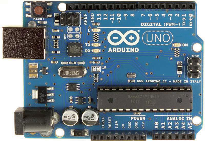
In this book, our focus will be on programming and configuring the Arduino as a TCP/ IP Client and Server. While the Arduino has numerous features, we will only discuss the ones necessary for our tasks, therefore excluding the majority of its features. Figure 3.1 illustrates the top view of the Arduino Uno.
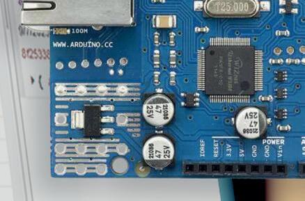
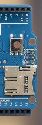
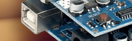
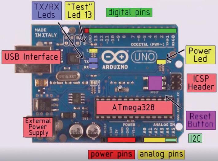
The figure labeled as Figure 3.2 displays the various components of the Arduino Uno. The first element is the USB interface, which serves two purposes: programming the Arduino development board and providing power to the Arduino. Essentially, the Arduino draws power from the USB interface. Additionally, the Arduino Uno can be powered by an AC/DC converter through an External Power Supply.
Furthermore, the digital pins section includes TX and RX female pins, which function as serial communication pins at the TTL level (ranging from zero to five volts). These pins facilitate serial communication with other devices and with the computer via the USB interface for programming. Digital devices can be connected through the digital pins, while analog devices (within the voltage range of zero to five volts) can be connected to the analog pins.
The power pins play a role in supplying power to both the digital and analog pins. In our case, we will utilize the digital pins to connect to an LCD display. This display will be used to present the data stored in the memory locations of the Arduino Uno.
Chapter 3 • The Arduino Uno
3.2:
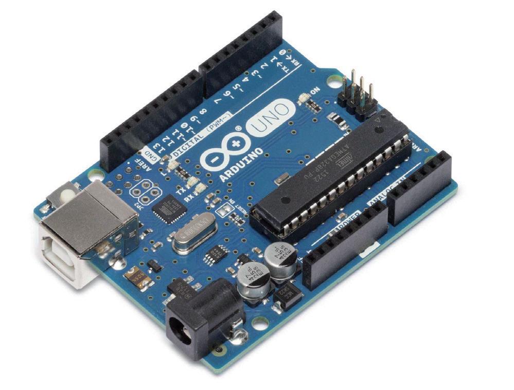
Figure 3.3: The 3D view of the Arduino Uno development board.
Figure 3.3 presents the visual depiction of the Arduino Uno development board in a 3D format. This provides a comprehensive understanding of the physical features and dimensions of the Arduino Uno hardware, which is known for its simplicity and compact size.
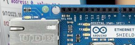
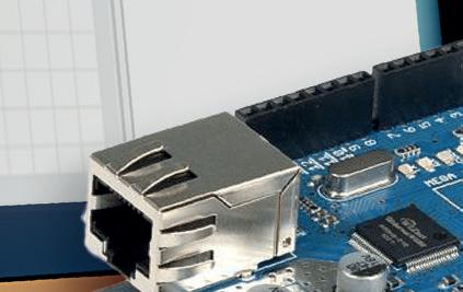
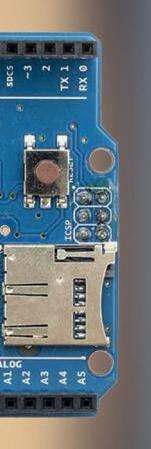
In this section, our focus will be on the Arduino Ethernet shield. Figure 4.1 illustrates how the shield appears. It is designed to perfectly fit on top of the Arduino Uno.
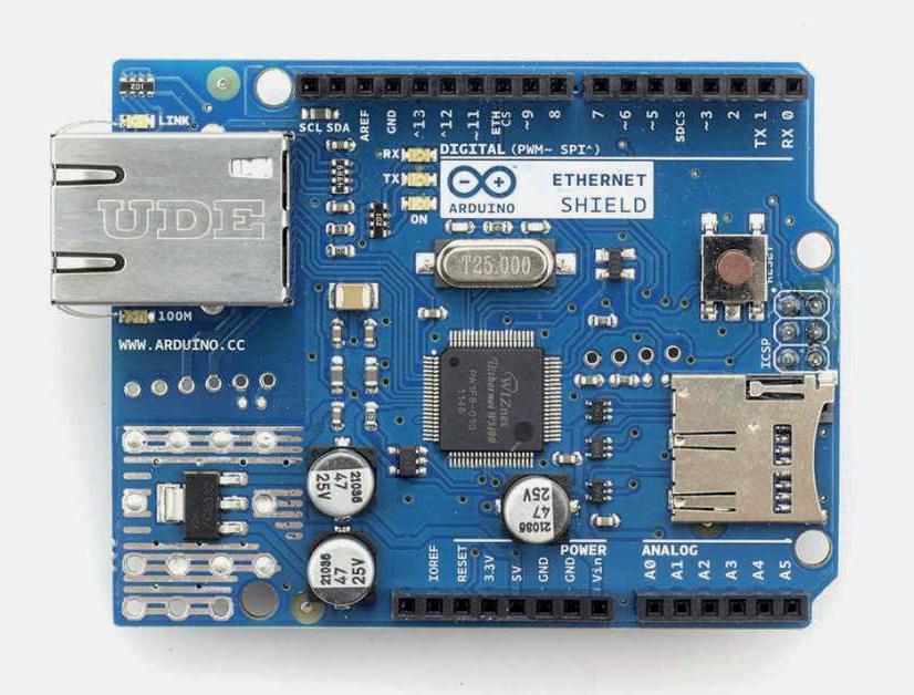
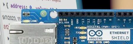
Figure 4.1: The top view of the Arduino Ethernet Shield.
On the shield, you can see identical sockets to those found on the Arduino Uno. These sockets directly connect to the pins on the Arduino Uno, making it stackable and allowing for communication through these pins. The Ethernet shield is necessary for our project, as it requires a TCP/IP network connection, specifically an Ethernet-based one. Although there are various types of TCP/IP networks, such as coaxial cable or fiber optic cable, we have chosen to use Ethernet on CAT5 cable due to its affordability, ease of use, and widespread availability. Additionally, the Ethernet Shield board features indicator lights that provide important information, so understanding their meaning is crucial.
The shield contains a number of informational LEDs:
PWR: indicates that the board and shield are powered.
LINK: indicates the presence of a network link and flashes when the shield transmits or receives data.
FULLD: indicates that the network connection is full duplex.
100M: indicates the presence of a 100 Mb/s network connection (as opposed to 10 Mb/s).
RX: flashes when the shield receives data.
TX: flashes when the shield sends data.
COLL: flashes when network collisions are detected.
So, if we are doing proper communication, we should see the TX and RX lights flashing a lot, and that is essentially the Ethernet Shield. Most of what you are supposed to understand are these lights. These indicator lights will give us feedback as to how the network is performing and how everything is working.
In the previous section, we provided a list of the hardware components used in the setup, particularly focusing on the Arduino Uno and the Ethernet shield for the Arduino Uno. In this section, we aim to present a visual representation or block diagram of how these components are interconnected to achieve the goals outlined in this book. Additionally, we will showcase the physical setup of this configuration on our workbench in the following section. By the end of this current section, you will have a clear understanding of the interconnections through the block diagram and a visual representation of the physical setup.
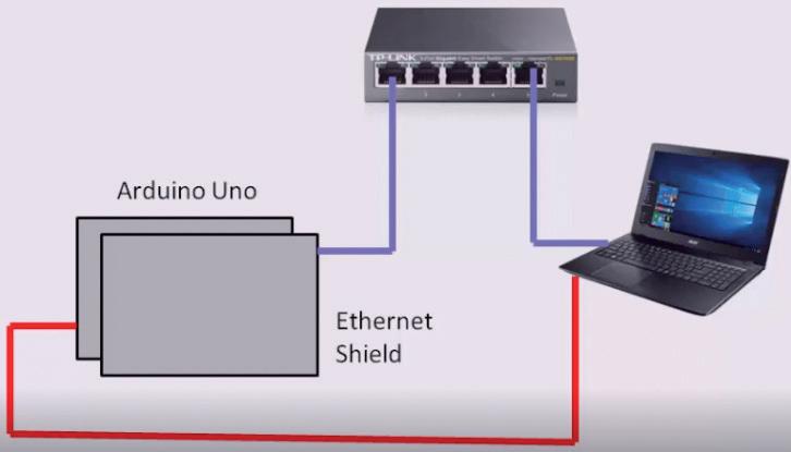
To begin, the main development board used is the Arduino Uno. This is then connected to the Ethernet shield for the Arduino Uno. Additionally, a network hub is incorporated into the setup. In our illustration, a five-port network hub is displayed, but in experimental scenarios, a 16-port network hub can be used. You have the flexibility to use a four-port or any other suitable option for your needs.
For the setup, only two ports are necessary. One port will be used to connect the laptop to the Arduino Ethernet shield, while the other port will be utilized for connecting the laptop to the network hub. Essentially, we are creating a small and simplified local area network for our Modbus TCP communication. Refer to Figure 5.1 for a visual representation of the required setup.
To set up the hardware, you will need to purchase some standard network cables (CAT5) called straight-through network cables and crossover cables, which are inexpensive and available at computer stores. Additionally, you will need a programming cable for the Arduino Uno, indicated by a red line, which is essential for any tasks involving the Arduino. The programming cable serves two purposes: programming the Arduino and receiving text messages from the running application through a special serial monitor window. This feature is particularly useful since the Arduino Uno lacks a visual interface. When working with Modbus and dealing with values in the Arduino and Modbus registers, it is crucial to be
able to visualize these values. Therefore, the application will be designed to send the values to the laptop via this cable, allowing for monitoring changes in value, reading and writing registers, and more. This summarizes the hardware setup, and in the following section, we will demonstrate how it appears on our desktop.
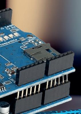
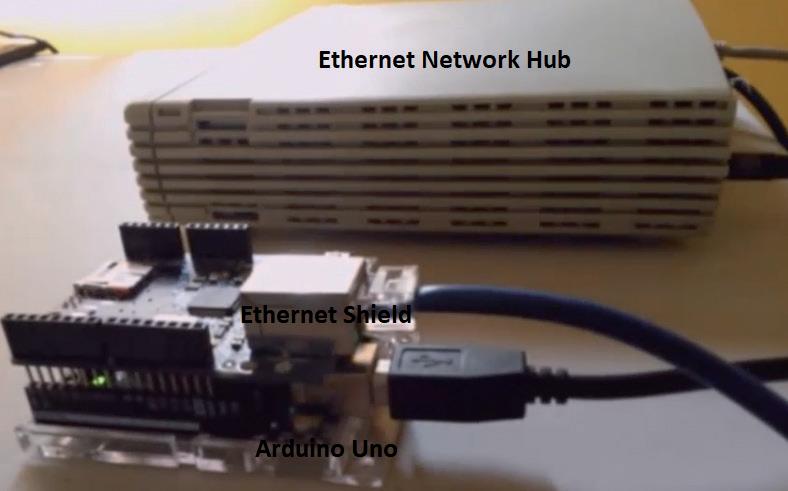
We are providing a visual representation of the physical hardware setup on the desktop, as in the previous section we only showed a diagram. Now, we will look at the actual setup. In Figure 6.1, you can see an Arduino with an Ethernet shield on top. The Arduino is located at the bottom, and the Ethernet shield is connected to it. The pins on the shield physically connect it to the Arduino. There are also indicator lights on the Ethernet shield that display different statuses. The Ethernet port is located on the shield, and a blue cable connects it to the Ethernet hub. The Ethernet hub has ports where the blue cable is inserted, specifically the port connected to the Ethernet shield on the Arduino. Additionally, there is a gray network cable that extends to the laptop, connecting to the Ethernet port.
This provides network connectivity to both the laptop and the Arduino via the Ethernet shield. The USB cable serves as the programming cable for the Arduino and allows for receiving feedback in the form of text messages. It is connected to the Arduino's port in order to program it. This configuration aligns with what was described in the previous section and is depicted in Figure 6.1. Now that you have a clear understanding of the setup, we can proceed with exploring various programming examples and how they appear on the desktop workbench.
In this segment, we will be discussing where to obtain the Arduino programming software, as well as the process of downloading and installing it. To get the software, we recommend visiting the official Arduino website at Arduino.CC. This website not only provides the software download, but also offers a plethora of resources for learning about Arduino basics, including information about both hardware and software. It is highly recommended that you explore this website to gain a better understanding of Arduino, especially if you are unfamiliar with it. However, in this particular section, our focus will be solely on the software.
To access the software, navigate to the "Software" section on the website. Although there is an online integrated development environment (IDE), we do not need that. Instead, we want to download the Arduino IDE. The IDE is an open-source software that enables easy coding and uploading to the Arduino board. By clicking on the Windows installer, you can save the current Arduino version to your device. If you wish, you can choose to contribute to support the open-source nature of Arduino. Otherwise, simply click on "Download" and save the file as an executable. After saving, double-click the executable to run a regular Windows installation process. We assume that you already have the knowledge of how to install Windows software. With these steps, you can obtain the Arduino software, which is completely free. We will demonstrate how to use the software in upcoming sections. For now, our focus is solely on downloading the necessary components.
In this section, we will demonstrate the libraries we plan to use in order to implement our Modbus server and client on the Arduino. We will provide information on where to download them, and once we begin coding, we will also guide you on how to utilize them. If you are unfamiliar with Arduino libraries, they are pre-existing pieces of code that eliminate the need for starting from scratch. Various individuals online have developed libraries for a wide range of purposes, including the Modbus TCP server and client. If you have experience implementing Modbus RS485 on the Arduino, you may have used libraries for that as well. The objective of this book is to download these libraries, incorporate them into our project, and utilize function or command calls within them. We will explain the process in detail, but it is important to understand that these libraries are code modules designed to simplify the process of writing programs for Modbus TCP server and client. In this book, we will download separate libraries for the Modbus TCP server and the Modbus TCP client. Attached to this book are two resources. The first is a link to the Modbus TCP server library. The weblink is as follows:
https://github.com/andresarmento/modbus-arduino
Once you click on it, you will be directed to a web page. On this webpage, you will find information about a Modbus library developed by Andre Sarmento specifically for Modbus TCP server implementation. This is the designated page for the library. Our request is for you to bookmark this page as you will need to refer to it for the provided documentation. Andre Sarmento has put together comprehensive documentation on using the library, making it a valuable resource. Upon reaching this page, your next step is to click on "Clone or download" and select "Download ZIP" as demonstrated in Figure 8.1.
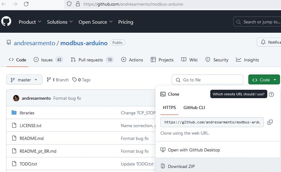
Figure 8.1: Clicking on "Clone or download" and "Download ZIP".
After clicking on the "Download Zip" button, a prompt will appear asking you to save the file. You should choose a folder to save it in. It is recommended to create a separate folder for your libraries, such as Arduino apps and Arduino libs (Arduino libraries). The Arduino app folder should be used to store all the applications you write, while the Arduino libs
folder is where the libraries will be stored. In this case, we downloaded a file called Modbus TCP server, which is mistakenly named Modbus Arduino master. To avoid confusion, we will rename the zip file to modbus_server_tcp.zip. Once you have the zip file, you should extract it by selecting "Extract All", which will create a folder with several subfolders containing libraries. You will see these folders as shown in Figure 8.2, but you do not need to use all of them, just some. Once you have downloaded and extracted the file, you are ready to learn how to use it later.
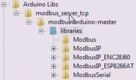
Figure 8.2: The modbus_server_tcp.zip extracted folders.
The subsequent resource in the attached section consists of downloadable files, specifically a file called MgsModbus.zip. It is not a hyperlink, rather a file that can be downloaded. The purpose of this file is to provide our library for implementing a Modbus TCP client. We chose not to direct you to a webpage because the file is directly accessible from myarduinoprojects. com. The corresponding weblink is as follows:
https://myarduinoprojects.com/modbus.html
The library featured on this page is not functioning properly due to the presence of several bugs. To address this issue, we have made necessary corrections to the library. The corrected version, which is guaranteed to work, can be downloaded from the appendix section of this book. Upon downloading, you will receive a file named MgsModbus.zip. Extracting this file will yield a folder containing two files, namely MgsModbus.cpp and MgsModbus.h, as shown in Figure 8.3.
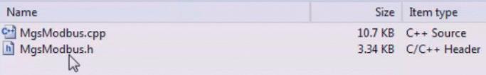
Figure 8.3: The files inside the MgsModbus.zip.
These are the library files needed for the Modbus TCP client implementation. After downloading and extracting these two files, store them in a location such as the Arduino Libs folder. It is important to keep them in one folder for easy accessibility. This completes the process of obtaining the Modbus libraries. In the coding phase, we will demonstrate how to properly use these libraries, as it involves steps like copying the files and including them.
The modscan32 and modsim32 download links are in the following weblink: https://www.win-tech.com/html/demos.htm
To complete the process, you will need to click on each of them individually. This will lead you to screens that will prompt you to download two files. The first file is modsim32. zip, which you will need to click on to start the download. After downloading it, proceed to download the second file, modscan32.zip. Once both files are downloaded, you can continue with installation. There is no need for installation, as the program runs without it.
Now, we have both modsim32.zip and modscan32.zip files. After extracting them, we obtained two directories: modsim32 and modscan32. To access modscan32, simply doubleclick on it, and you will see the file named MODSCAN3.exe, as shown in Figure 9.1.
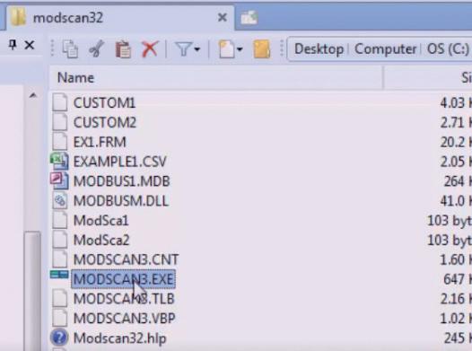
Figure 9.1: MODSCAN3.exe in the modscan32 folder.
This is the executable that you want to run, and you should create a shortcut to your desktop, which is a shortcut to this executable file. So, when we double-click on that, it just runs as depicted in Figure 9.2. We do not have to do any installation process and we are going to use modscan32 as a Modbus TCP client when we configure the Arduino as a Modbus TCP server. So modscan32 is going to be used to communicate with it and will be reading data from the Modbus TCP server (Arduino).
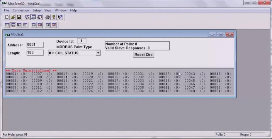
Figure 9.2: Running the MODSCAN3.exe file.
In the modsim32 folder, there is an executable called modsim32.exe. You can create a shortcut for it. When you double-click on the shortcut, a modsim32 pop-up window, as shown in Figure 9.3, will appear.
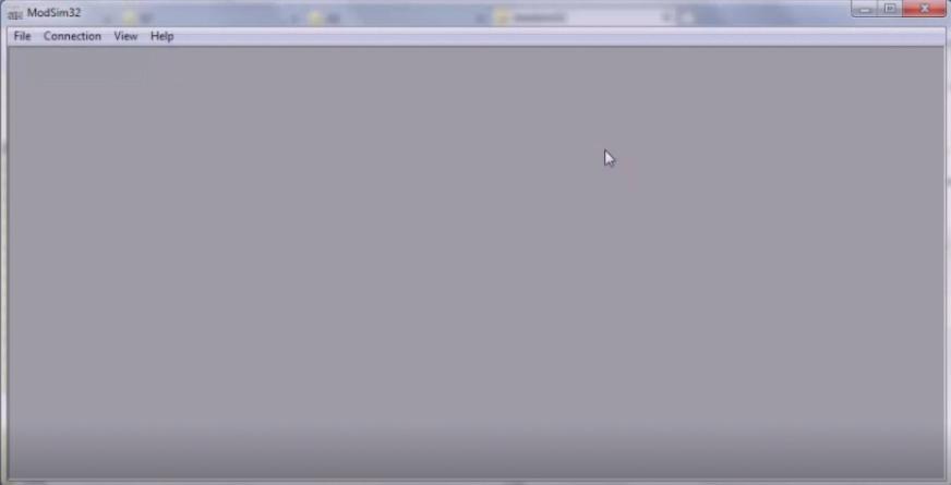
Figure 9.3: The modsim32 pop up window.
We will use modsim32 as a Modbus TCP server when configuring the Arduino as a Modbus TCP client. This means that the Modbus TCP client will read data from modsim32. Throughout the rest of this book, we will be using two Windows-based Modbus applications called modscan32 and modsim32. As we progress through the sections and develop various applications, you will learn how to use these applications.
Now that you understand what the hardware looks like, and you may have already downloaded some software, it is important to note that you may not have the hardware in front of you at the moment. However, once you see how amazing and affordable the hardware is, we are confident that you will acquire it and revisit the book to try it out yourself. In this section, our aim is to introduce you to the Arduino programming software, which is known as the Arduino IDE, or Integrated Development Environment. But before we proceed with that, it is worth mentioning that when the Arduino software was installed, it would have also installed a device driver. This driver, when connecting the Arduino to your laptop or PC via a USB cable, creates a virtual COM port. We encourage you to look at this virtual COM port now by accessing the device manager and navigating to the ports section. As shown in Figure 10.1, you will find it there.
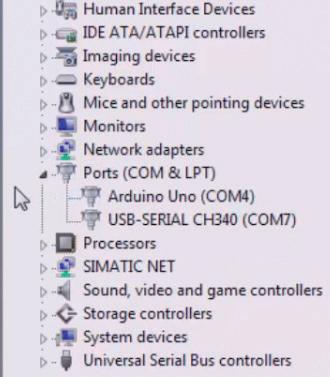
10.1: Ports in the "Device manager".
Before you begin programming the Arduino, make sure to check your port settings. The port should be set to Arduino Uno COM4, although it may be different for your specific device. Additionally, there is another virtual COM port called COM7, which is our USB to RS485 converter.
Moving on, the Arduino icon can be seen in Figure 10.2, and this is what you should store once you have installed and started it. In Figure 10.3, you can see the Arduino development environment. This is where you will write your code, compile it, and download it into the Arduino to make it work. While there are many features available, we will only focus on the ones that are most important and commonly used in the book's projects. The code area, as depicted in Figure 10.3, is where you will write your code.
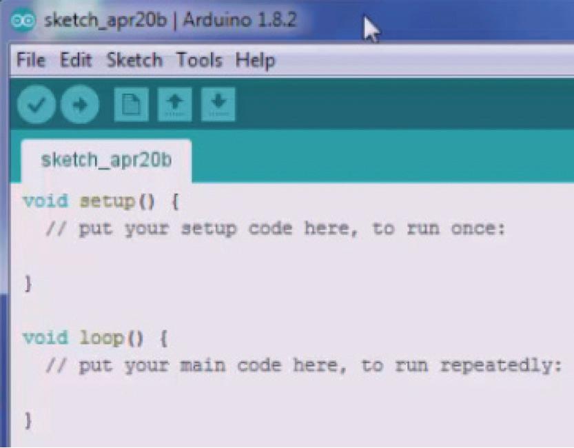
Figure 10.3: The Arduino IDE code area.
We will briefly discuss that, however, the primary tools you use in this setting are the buttons located at the top. We will go through each one individually. The button labeled "Verify" is the same as the compile function shown in Figure 10.4.

10.4: The "Verify" button.
After writing your code, when you are prepared to compile it and check if it is functioning properly, you will click on the upload button as shown in Figure 10.5. However, despite being labeled as "Upload," this button transfers your code and program to the Arduino board. This difference in terminology is similar to a US-Europe distinction. In the US, you would typically say "Download" to the Arduino, while in Europe, the term used is "Upload." Nonetheless, the objective remains the same: to transfer the program successfully into the Arduino board.

Figure 10.5: The "Upload" button.
By using the button illustrated in Figure 10.6, you can generate a fresh window. When you select the "New" option in the Arduino interface, a completely new window opens instead of opening an additional tab.

Figure 10.6: The "New" button.
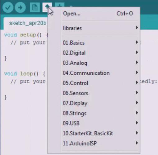
If you wish to open an existing project, you can use the Open button depicted in Figure 10.7. Furthermore, to save your project or code, use the button shown in Figure 10.8.

These buttons are the most often used by us. We are now asking that you perform an action: navigate to file preferences and select the option to display line numbers. We believe having line numbers is beneficial, and for that reason, we have demonstrated this in Figure 10.9 and Figure 10.10.
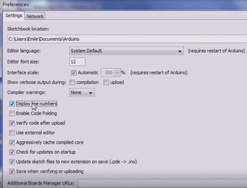
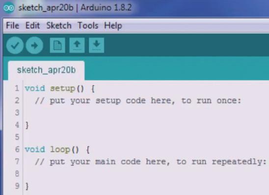
Figure 10.10: Displayed line numbers.
As shown in Figure 10.10, the top menus on this interface, such as "Verify," "Compile," and "Upload," perform similar functions. Many of these menu items have not been used yet. Now let us look at the user window, which is the code area. When starting a new project, some code is automatically provided. This includes two functions that are present in every Arduino program: setup and loop. The comment in the code area states that the setup function is for initialization, and the loop function is for the main code that will be repeatedly executed, similar to how a PLC operates. Embedded systems typically work by continuously repeating the code placed in the loop function. On the other hand, Windows operates on an event-based system, where applications run differently.
When you are ready, you can click on the "Verify" button, even if there is no code present. This will initiate the sketch compilation process, and it will show a "Done compiling" message. Currently, we are connected to our Arduino device. To confirm this, go to the "Tools" menu, click on "Port," and select the appropriate communication port. This port selection will remain active once you have made your choice, as shown in Figure 10.11. When initially opening the Arduino development environment, you will need to go through this process of selecting the port.
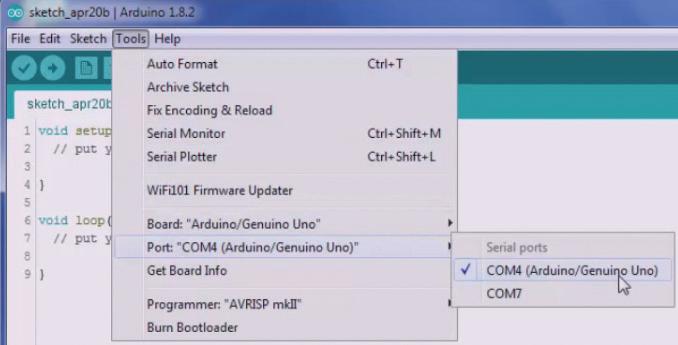
Figure 10.11: Choosing your communication port.
We have gathered our program here and will now try to initiate the download process. After recompiling, the program states "Uploading" and then "Done uploading." This indicates the completion of the upload and signals that the Arduino will begin executing the new program. The Arduino IDE is relatively straightforward compared to software like Microsoft Visual Studio, which has an abundance of buttons and menu options. This concludes a brief introduction to the Arduino IDE. In the later section, we will proceed with our first application, downloading it and observing its functionality.
projects with Node-RED, MQTT, WinCC SCADA, Blynk, and ThingSpeak
This comprehensive guide unlocks the power of Modbus TCP/IP communication with Arduino. From the basics of the Modbus protocol right up to full implementation in Arduino projects, the book walks you through the complete process with lucid explanations and practical examples.
Learn how to set up Modbus TCP/IP communication with Arduino for seamless data exchange between devices over a network. Explore di erent Modbus functions and master reading and writing registers to control your devices remotely. Create Modbus client and server applications to integrate into your Arduino projects, boosting their connectivity and automation level.
With detailed code snippets and illustrations, this guide is perfect for beginners and experienced Arduino enthusiasts alike. Whether you‘re a hobbyist looking to expand your skills or a professional seeking to implement Modbus TCP/IP communication in your projects, this book provides all the knowledge you need to harness the full potential of Modbus with Arduino.
Projects covered in the book:
> TCP/IP communication between two Arduino Uno boards
> Modbus TCP/IP communication within the Node-RED environment
> Combining Arduino, Node-RED, and Blynk IoT cloud
> Interfacing Modbus TCP/IP with WinCC SCADA to control sensors
> Using MQTT protocol with Ethernet/ESP8266
> Connecting to ThingSpeak IoT cloud using Ethernet/ESP8266

Majid Pakdel, born in 1981 in Mianeh, Iran, has a PhD in Electrical Engineering and an MS in Computer Engineering focusing on AI and Robotics. He has published 20+ papers and 4 books. He was a visiting PhD student at Aalborg University in Energy Technology from 2015-2016.
Elektor International Media www.elektor.com