


L L II N N E E S S & & P P O O II N N T T S S www.plsw.org Volume 34: Issue 3 July, 2023 THE EQUALITY STATE SURVEYOR Professional l and s urveyors of Wyoming

Lines & Points (Vol. 34: No. 3) 1|Page
President President Elect Secretary/Treasurer
Thomas A Johnson, PLS
Doug Boyd, PLS
John “Jack” Studley, PLS
LeveLing down the traiL into gLen Canyon. LeveL party of fred e. JoeCkeL gLen Canyon, arizona. 1921.
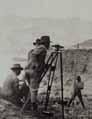
Credit: C&gS SeaSon’S report JoekeL 1921.7
CONTENTS
Page 3
Page 4
Page 6
Committee Chair-Chief Editor Designer Treasurer & Advertising Circulation
Copy Editor Website Emeritus Member
John Lee, PLS
Cotton Jones, PLS Area Director Wyoming Delegate
Publications committee
Steven “Dennis” Dawson, PLS dennieandbarb@gmail.com
Michael Flaim, PELS mike.flaim@bresnan.net
John “Jack” Studley, PLS jklz0318@gmail.com
Joel Ebner, PLS jvebner@bresnan.net
Herbert W. Stoughton, PhD, PELS, CP hws.geod.engr@gmail.com

Sonja “Suzie” Sparks, PLS sasparks7@gmail.com
Pete Hutchison, PELS petehpels@gmail.com
PLSW (Professional Land Surveyors of Wyoming; PO Box 8, Cheyenne, WY 82003) is a statewide organization of Land Surveyors registered to practice in the Equality State of Wyoming. PLSW is dedicated to improving the technical, legal, and business aspects of surveying in the State of Wyoming. PLSW is affiliated with the National Society of Professional Surveyors (NSPS) and the Western Federation of Professional Land Surveyors (WestFed).
Lines and Points is published by the Professional Land Surveyors of Wyoming. Lines and Points is not copyrighted and permission is hereby granted to reprint articles with appropriate credit. The Professional Land Surveyors of Wyoming assume no responsibility for statements made or opinions expressed in this publication. The articles and opinions as put forth in this journal are not necessarily those of PLSW or the Editorial staff of this journal.
Page 9 Page 13 Page 20
PRESIDENT’S MESSAGE ANNOuNCEMENTS
GLENVILLE STATE uNIVERSITY PROFESSOR
INVENTS NEW SuRVEY TOOL
by: Christian Meffert
WHAT IS PASSIVE CONTROL AND WHY IS IT IMPORTANT?
by: Brian Shaw
kEEPING BOTH FEET ON THE GROuND
by: Michael A. Flaim, PE, PLS
METRIC CORNER
by: Dr. Charles A. Whitten
•Jennifer Dibona - That CAD Girl
•Jason Dysthe - Frontier Precision Inc.
•John Baffert - Surv-KAP, LLC
•Kelly Goff - Underground Consulting Solutions

•Susan Hall - Trimble
•Tim Klaben - Berntsen International Inc.
•Troy Langston - Monsen Engineering
Advertising Information
Digital-ready, full-color advertising with payment should be mailed to Lines & Points, P.O. Box 8, Cheyenne, WY 82003. Advertising rates are as follows: Year Issue
Full Page $810 $210
Half Page $540 $140
Quarter Page $310 $80
Business Card $40 $10
Employment Free Free Special Rates apply for PLSW Chapters and cover placements. For more information please contact Jack Studley.

On The Cover L II N E E S & & P P O O II N N T T S S www.plsw.org Volume 34: Issue July, 2023 THE EQUALITY STATE SURVEYOR
April 2023 Page|2
PRESIDENT’S MESSAGE
I hope we are all working on interesting, profitable projects at this time. These are the days for it, our work environment is at its most green and lush for the year, and it is a great time of year to be a surveyor.
It does not seem to be a great time to be in business, however. The need for people to work is still greater than the people’s need to work. I am hearing this from all sectors; from unskilled labor, restaurant help, to heavy equipment operators, and engineers and surveyors. No matter how robust you have been in your work skills, we all need to wear the hats of secretary, bookkeeper, EHS, etc. as well. It makes it tough on the consumer when people have to wait exceptionally long for all goods and services.
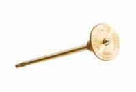
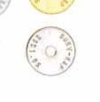
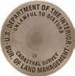
Something interesting popped up on my computer the other day. The product I speak of is described as a property boundary marker. I think you can understand why that caught my attention. The type that popped up for me was a dome headed barbed point pin of solid brass. I started looking a bit and I found that Amazon has quite a variety of survey markers for sale. The selling pitch for these is of course that these are more convenient than hiring a surveyor. Their advantage is there is nothing sticking up that you have to mow around. I often talk to landowners who think that the lath and/or stake that we set along side our
monument is the actual monument. It surprises them to find out that we drive a 24” rebar and attach a marked cap. We also make a judgement call each time about how much of the monument to leave sticking out of the ground, definitely flush, if in an area likely to be mowed.
The monument that I found online is 10” long. At 2-5/8” diameter the top of this monument is somewhat bigger than what we commonly set, but at $69 each, they are pretty pricey. They certainly do not meet the minimum monument standard for Wyoming. In the world of Amazon shopping, maybe I should be surprised that I have not found something like this set on a property. But we should all be looking out.
Have a great rest of your summer!
Best Wishes to all, Tom
Thomas Johnson, PLS President Professional Land Surveyors of Wyoming


PLSW.org WEB REQUEST
As you the reader may or may not know, PLSW has launched a new website to serve the organization and it’s membership. The request to the members to submit videos and photos to be used in the website is always open. The more of that digital information that we can provide, the better the website will be. Please continue to submit your contributions to my personal email and I will forward the data to Edge Marketing Design.
Every contribution that you make will make our Website better.
Thanks!
Dennis Dawson, PLS
My Email is: dennieandbarb@gmail.com
I encourage you, the reader, to review the current new website: www.plsw.org
3|Page Lines & Points (Vol. 34: No. 3)
The Bureau of Land Management Cadastral Survey Requests your Assistance
The BLM (we) are working to improve the control data in our PLSS data set (PLSSds), a.k.a. Geographic Coordinate Database (GCDB) project. With your help we would like to create a better, more comprehensive solution with improvements to the PLSSds. Benefits to the surveyor will include more reliable search coordinates and more accurate location data, which will benefit your clients who use the corporate GIS. Your feedback is critical to the success of this project.
Current reliability of the PLSS data:
During the GCDB project beginning in 1989, data collection was completed using the latest official FEDERAL survey record adjusted to digitized corner positions. It offered a robust least square adjustment process and reliability adjustments to control movement of old to new survey data. This ensured that new data with surveyed control did not move to old data with digitized control. It also eliminated gaps or overlaps between townships of the collected data. Since then, BLM has added coordinates from its surveys of Federal interest lands to the PLSSds. This has improved the reliability in some locations considerably but there are areas of the State where the PLSSds is still based on antiquated measurements of original surveys or digitized control.
A few examples where PLSS corners are being visited by licensed surveyors, but there is no mechanism for either the Federal agency or the surveyor to share the survey data with the BLM:
1. Patented lands. BLM has no authority to survey non-Federal lands. Once patented, we lose the ability adjust to actual surveys conducted under State authority.
2. Rural land owners to subdivide or for water rights maps
3. Federal land for well pads, pipelines, BIA, Tribes, or other Federal agencies transferring land such as Forest Service using Small Tracts Act authority or disposal by other agencies
Why this Matters:
The MAPLAND Act of 3/16/2022 “will direct federal land management agencies to digitize and standardize mapping records. This will allow hunters, hikers, bikers, anglers, and millions of other federal land users to access essential information about public lands as well as help federal land management agencies identify public lands with limited or nonexistent public
access points and take proactive steps to open them to the public.”
The Act is an unfunded mandate and does not direct us to improve the data, only to make it available to the public. The underlying ramifications of not improving the data will cause further confusion among users since there are several State agencies that publish their versions of the PLSS. OnX Hunts and other privately owned companies mine State and Federal data and are publishing variations of the PLSS data.
Proposed Solution:
Our proposed solution is to create a web portal in Lines and Points for submission of PLSS corner data. We would like to make it easy for the surveyors to contribute and will accept current and past data. The data shared by you will be secured and the meta data will only show source as from private survey data along with reliability estimate.
Options
1. upload copy of unstamped, unsigned corner record that includes
a. Description and condition of recovered monument
b. Reference Frame
c. Latitude (DD MM SS.SSS)
d. longitude (DD MM SS.SSS)
e. Sketch or photo
2. upload data to spreadsheet template that includes
a. Description and condition of recovered monument
b. Reference Frame
c. Latitude (DD MM SS.SSS)
d. longitude (DD MM SS.SSS)
e. Sketch or photo
Please send your comments (positive or negative), whether you like one of the options, and proposed alternatives to:
Suzie Sparks, Chief Cadastral Surveyor for Wyoming & Nebraska
s75spark@blm.gov
Questions? 307-775-6225 or 307-275-5014
ANNOUNCEMENTS
Page|4 July 2023
L L II N N E E S S & & P P O O II N N T T S S H ints to A ut H ors
Dear Readers:
The editors of Lines & Points wish to convey our gratitude to the numerous authors who have contributed photographs, technical and professional articles, and other information to be incorporated into the quarterly journal. In recent years, the assembly and redaction of the submitted materials has taken on considerable technical application of the various English language compilers, office suites, and “publishing suites”. This means that the communication and transfer of information and materials arrive at the editors’ desktops in a multitude of formats and styles, which sometimes are not compatible with the PLSW personal computers.
We, the editors, are setting forth some simple rules for submitting materials which, hopefully will simplify your efforts and make the transition to the published version simpler and less time consuming.
1. If you have any questions or comments, please contact S. Dennis Dawson, Publications Comm. Chm., (dennieandbarb@gmail.com) or Michael A. Flaim, Editor-in-Chief (mike.flaim@bresnan.net).
2. If an article contains any illustrations, photographs, graphs, or other graphics, please transmit them as separate individual files. You may also include the illustrations within your manuscript, but the image integrity/quality is degraded seriously when attempting to extract them from the manuscript to create a published digital image. The Editor-in-Chief states that a much better digital resolution is obtained from the separate, individual illustrations submitted.
3. All submissions (electronic and snail mail) should be sent to S. Dennis Dawson (4005 Snyder Avenue; Cheyenne 82001). It is recommended a second copy be sent to Michael A Flaim (1212 Southwest Drive; Cheyenne 82007). It is further recommended a third copy be sent to Dr. Herbert W. Stoughton (2829 Carey Avenue: Cheyenne 2001. Dr. Stoughton has spent over two decades as a technical review editor of two national surveying journals, and will provide editorial/redactory review for grammatical presentation and punctuation format. The criteria for acceptable conformity to grammatical usage and punctuation shall be governed by the u.S. Government Printing Office Style Manual (any edition is acceptable).
4. It is strongly recommended that all submissions be transmitted six weeks prior to the publication deadline. The publication deadlines are: 1 January; 1 April; 1 July; and 1 October, annually.
5. Lines & Points is the official publication for the Professional Land Surveyors of Wyoming. Therefore, hence forth there will be incorporated in the publication all formal announcements pertaining to official business of the organization and other announcements. This includes announcements for the Annual Meeting; state-wide membership meetings; seminars; and the Fall Technical Session. These announcements are to be submitted to the PLSW Secretary/Treasurer John J. Studley (PLSW; Attn.: Mr. Jack Studley; P.O. Box No. 8; Cheyenne 82003) (jklz0318@gmail.com), at least four weeks prior to the publication deadline in which the announcement will appear. The PLSW Secretary/Treasurer will circulate the announcements to the Publication Comm. Chm.; the Editor-in-Chief; and the PLSW Board of Directors.
6. Advertisers and prospective advertisers should communicate directly with PLSW Secretary/Treasurer Studley about any advertisements and modifications.
Lines and Points articLe rotation submission scheduLe by chaPter
upper Platte Chapter September 1 September 15 October 1, 2023
Southwest Chapter December 1

Northeast Chapter March 1
Northwest Chapter June 1
West Chapter September 1
Central Chapter December 1
South Central Chapter March 1
December 15, 2023 January 1, 2024
March 15
June 15
September 15
April 1, 2024
July 1, 2024
October 1, 2024
December 15, 2024 January 1, 2025
March 15 April 1, 2025
Responsible Chapter First Call Date Last Call Date Publication Date
Southeast Chapter THANK YOU!! (see “KeepiNg BOTH feet ON THe grOUNd” iN THis issUe)
5|Page Lines & Points (Vol. 34: No. 3)
Glenville State university Professor Invents New Survey Tool
Christian Meffert
Glenville, W. Va. - A Glenville State university (GSu) professor has developed a tool that will help surveyors deal with a difficult concept, even without special training.

According to a release from GSu, Jacob Petry, a lecturer of land surveying at GSu, created the Pathfinder to help himself and others work around geomagnetic secular variation, which is a gradual change to Earth’s magnetic field.
“I remember being told as a student that it was no reflection on our ability to learn, but some of us would understand secular change, and some wouldn’t - I fell into the second category. Then, after spending several hours working mathematical computations and trying to visualize two magnetic norths that varied slightly, the idea for the directional conversion tool appeared,” said Petry.
To create the prototype, Petry worked with his brother kaleb, “an Army pilot and expert land navigator,” the release said.
According to Builder’s Book, California-based company that sells the product, Pathfinder is labeled as a tool that helps surveyors with secular variation “without the need for advanced tools or specialized training.”


“I’m proud of the Pathfinder, and seeing it on the market brings me joy. I believe aspiring land surveyors will receive as much help out of it as I have,” Petry. said.
The Pathfinder: Directional Conversion Wheel can be purchased online at www.buildersbook.com ($22.45 plus $12.95 S&H)
■ Digital Aerial Photography ■ LIDAR ■ Mobile Mapping ■ Topographic Mapping ■ Orthorectified Imagery 40 West Oakland Avenue, Salt Lake City, UT 84115 · PHONE: 801-487-3273 · Fax: 801-487-3313
originaLLy pubLiShed in the georgia Land Surveyor; Spring 2023; p. 34. Page|6 July 2023
2023 CFEDS PROGRAM PROMOTIONS STATE SURVEY SOCIETY INVITATION

The Certified Federal Surveyor (CFedS) program is an intensive course designed to equip licensed surveyors with an unsurpassed Public Land Survey System (PLSS) knowledge base. Created in 2005 by the Bureau of Land Management, CFedS has become the hallmark program for surveyors wishing to provide cadastral services on federal trust lands while deepening their understanding of working within the PLSS. The non-PLSS surveyor can also benefit from the program by becoming more well-rounded in the many intricacies of our profession.

In early 2022, we embarked on a mission to modernize the CFedS o ering, bringing the program online for the first time. While this was no small undertaking, I’m proud to say that the core seven-course training series is now delivered via www.cfeds.org. Close to 75 individuals are working through the material as of this writing with another 520+ active professionals among our ranks.
As this initiative is important to both CFedS members and NSPS, we’d like to increase regional engagement via continuing education presentations with societies such as yours. We partnered on 9 such sessions in 2023 and are looking to expand this number in 2024. If you’re able to consider a CFedS presentation within your 2024 conference, please touch base with me at the address below.
From a national perspective, the CFedS program hopes to get our message out in as many venues as possible. To make all surveyors aware of this educational opportunity, we’ve created a range of promotional materials for use within state society publications (full and half page options) + websites which are available at: www.cfeds.org/media-resources/
It would be greatly appreciated if you could share these materials with your membership. Interested surveyors can visit our webpage at www.cfeds.org or contact me directly at glen.thurow@cfeds.org to discuss further collaborations.
I appreciate your consideration of this request.

CFEDS TRAINING COORDINATOR - DIRECT: +1 (505) 274-8571 - WWW.CFEDS.ORG GLEN.THUROW@CFEDS.ORG - PO BOX 91393, ALBUQUERQUE, NEW MEXICO 87199
Glen W. Thurow, NM P.S., CFedS CFedS Training Coordinator
7|Page Lines & Points (Vol. 34: No. 3)
The Certified Federal Surveyor (CFedS) program, founded 2005, is produced by the Bureau of Land Management (BLM) in conjunction with the National Society of Professional Surveyors (NSPS).


MASTER FEDERAL BOUNDARIES INTENSIVE ONLINE TRAINING PROGRAM NOW AVAILABLE The Certified Federal Surveyor (CFedS) program is the United States’ pre-eminent public and tribal land survey certification since 2005. Apply today at cfeds.org CFedS-AdCampaign-Final.indd 8 3/22/23 3:47 PM INTENSIVE ONLINE TRAINING PROGRAM NOW AVAILABLE MASTER THE FEDERAL LANDS The Certified Federal Surveyor (CFedS) program is the United States’ pre-eminent public and tribal land survey certification since 2005. Apply today at cfeds.org CFedS-AdCampaign-Final.indd 7 3/22/23 3:53 PM Page|8 July 2023
WHAT is pAssive CONTrOl ANd WHY is iT impOrTANT?
By Brian Shaw, Rocky Mountain Regional Advisor (CO, MT, WY) NOAA’s National Geodetic Survey (NGS)
Passive Control has been instrumental to the mission and success of the National Oceanic and Atmospheric Administration’s (NOAA) National Geodetic Survey (NGS) throughout its history, which dates back to 1807 when Thomas Jefferson created the Survey of the Coast. Prior to the creation of NOAA in 1970, NGS’s predecessor agency was the united States Coast and Geodetic Survey (USC&GS). USC&GS had been the office’s name for almost 100 years and many of the survey marks you will find throughout the United States and its territories have uSC&GS stamped on them. These marks were established primarily for horizontal and vertical positioning, and the survey observations between them were used to help determine both the datums of the past, and the datums we still use today. For over a century these marks in the ground have formed the foundation of the National Spatial Reference System (NSRS), a consistent coordinate system that defines latitude, longitude, height, scale, gravity, orientation, and shoreline throughout the united States. Passive control and the datums derived from them are truly the infrastructure of our nation’s infrastructure. Highways, railroads, bridges and more rely on these marks in the ground and the surveys performed using them.
While today we rely more heavily on the GNSS “stars” in the sky for positioning, these marks in the ground will continue to be important and should be perpetuated whenever possible.
Passive control is a term applied to survey marks that are “permanently” monumented and infrequently surveyed, whereas the term active control was developed for Continuously Operating Reference Stations (CORS), as well as other geodetic techniques that are constantly collecting data. Passive control includes brass marks in the ground, 3-D deep driven rod marks, and many other types of monuments that were established to weather time and the elements, providing a location for surveyors to use to access the geodetic datum. The Geodetic Glossary1 has a number of definitions that can be used for passive control, and one definition is control point: “A point to which coordinates have been assigned; these coordinates are then used in other (dependent) surveys.” There are many synonyms for passive control including control point, geodetic control, monument, station, mark, survey mark, bench mark and many more. In the past, some of the different terms were originally intended for use with specific types of control –for instance bench mark was used for marks with a precisely determined height, also known as vertical control – but today most of these terms have become generalized as a term applied to all survey marks.
For over 200 years NGS has spent a considerable amount of money and effort establishing control across the united States and territories. This was done primarily to determine precise coordinates

Year Datum Stations 1901 u.S. Standard Datum 5,000 1927 North American Datum of 1927 25,000 1983 North American Datum of 1983 272,000
Table 1 - Growth of the networks in the united States2
Chart 1 - Distribution of Control Marks Established by
Decade.
9|Page Lines & Points (Vol. 34: No. 3)


 Figure 2 -u.S. Horizontal Control Network in 1927 (Figure 4.2 NOAA Professional Paper NOS 2)2
Figure 1 - u.S. Horizontal Control Network in 1900 (Figure 4.1 NOAA Professional Paper NOS 2)2
Figure 4 - Status of Vertical Control u.S. in 19834
Figure 2 -u.S. Horizontal Control Network in 1927 (Figure 4.2 NOAA Professional Paper NOS 2)2
Figure 1 - u.S. Horizontal Control Network in 1900 (Figure 4.1 NOAA Professional Paper NOS 2)2
Figure 4 - Status of Vertical Control u.S. in 19834
Page|10 July 2023
Figure 3 - Status of Horizontal Control u.S. in 19833
(positions and heights) by performing extensive surveys across all states and territories, and sometimes even surveying in other countries. The Survey of the Coast originally established control and performed surveys to determine coordinates for locations on shore as well as offshore. These surveys determined where places were on land, but also mapped offshore obstructions – such as sea mounts, rocks and sand bars – to develop accurate nautical charts in support of safer navigation. As our country grew and the surveys spread across our growing nation, this control was used to determine national datums for positioning, ensuring our nation had a consistent coordinate system for all to use.
The growth of our national network can be seen in maps of the survey control networks of Figures 1, 2, 3, and 4, as well as, by looking at the total station counts in Table 1 and Chart 1. In 1901 the US Coast and Geodetic Survey released the first major nation-wide datum adjustment called the united States Standard Datum of 1900 (uSSD), which included coordinates on 5,000 control stations. Surveying increased and the network greatly expanded so when the North American Datum of 1927 (NAD 27) was released there were 25,000 control stations. Just after NAD 27 was realized our nation fell into the Great Depression. As part of Franklin D. Roosevelt’s New Deal, the Works Progress Administration (WPA) and

11|Page Lines & Points (Vol. 34: No. 3)
other similar programs helped the uSC&GS hire unemployed surveyors and engineers. These programs enabled the uSC&GS to perform more surveys across the nation, significantly helping to develop the geodetic infrastructure and datums we have today. You can see this major increase in the chart that shows the dates that marks were first established in the NGS database. The 1930s were by far the most productive decade for establishing new control across our nation from ~18,000 new marks in the 1920’s to ~144,000 new marks in the 1930s, an eight fold increase. By the time the North American Datum of 1983 (NAD 83) was established there were 272,000 stations included in the datum adjustment, making it the largest
mathematical equation ever solved at the time.2
As you can see by the progression of the maps, there was a tremendous amount of surveying accomplished between NAD 27 and NAD 83. This included surveying the 272,000 horizontal stations used in the NAD 83 adjustment2 and 505,000 permanently monumented bench marks and 204,000 temporary bench marks with over 730,000 km of geodetic leveling for the North American Vertical Datum of 1988 (NAVD 88) adjustment.5 The amount of people hours it took to accomplish this was a monumental feat. Horizontal survey
(Continued on Page 18)
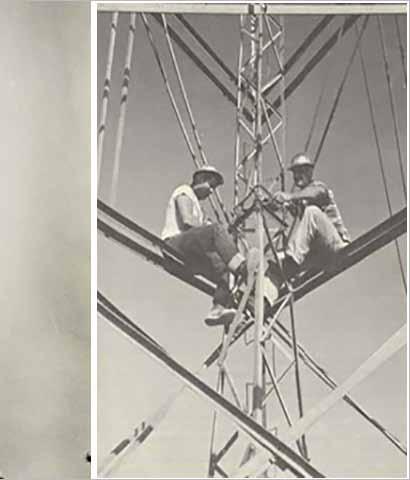
Photo 1 - u.S. Coast and Geodetic Survey surveyors on Bilby Towers.6
Page|12 July 2023
KeePing both feet on
the ground?
By Mike Flaim, PLS, PE
Have you “internationally” stubbed the toe on your “uS survey” foot yet? Well, let me tell you the most recent tale of cleaning my sole of the pile I stepped in.1
First some background. At the Wyoming Department of Transportation (WYDOT) our standard process of mapping the existing field conditions of any project begins with establishing a project’s ground coordinate system for design and construction. To do this, we make measurements utilizing a GPS survey system employing a Rapid Static network of observations which are further constrained/adjusted with additional OPuS Projects observations on our primary control monuments. These final geodetic coordinate values are reported in meters. The coordinates are then projected onto the appropriated state plane zone (a metric calculation) and the National
Geodetic Surveys (NGS) derived Geoid model is utilized (with Geoid separations in meters ) to produce metric plane coordinates. Then we use differential leveling field procedures to enhance our confidence of the vertical component of our project’s coordinates. Again, with all measurements in meters . A final step of calculating the Datum Adjustment Factor (DAF), which is the average of the individual combine scale factor of all the project’s primary control monuments. This is multiplied by the State Plane Coordinates (SPCs) to arrive at the final project ground coordinates and elevation for each of the project’s primary control monuments. Walla! We have our feet firmly placed on the ground...in the metric system!
Now the surveyor in me has “happy meter feet,” but the ‘gineer2 side of me knows that “one
Figure 1: Original mapped data sets of bridges BFB and BFC.
13|Page Lines & Points (Vol. 34: No. 3)
size shoe doesn’t fit all.” These values must be converted to feet in order to communicate with my fellow ‘gineers! In fact, I need to further divide thems feet by 10 for some mapped distances, but also multiply by 5280 for others, in some cases divide thems feet by 12 for hydraulics, multiply thems feet by 3 for volumes, oh and don’t forget multiplying thems feet by 43,560 (10 square of thems 66-foot chains) to get acres for the hydrology folks! Tell me again why the attempt to convert to the metric system back in the 70s was so hard to wrap our heads around?
I think you can see how my “foot” is about to step in this fresh pile of... Now some of you may be saying, “…but, Mr. (half) surveyor, the difference between your feets conversion is 1.000002 and, therefore, your distance measurement has to be almost 3 miles (4.8 km) long before that conversion difference exceeds your equipment’s ability to accurately measure said distance. It is unnecessary to trouble your silly head about such insignificant things when calculating cubic yards of earth being moved by big machines (insert tool man grunts here)! It is the proverbial Dust in the Wind.”3.2808 Ah, you are correct in stating that the conversion on the length of a 100 foot long bridge is insignificant but its correct location within the project’s mapping is—let’s just say—no small feet!
Anyway, the good folks at National Institute of Standard and Technology (NIST) decided that we had too many styles of shoes for our feets back in 2022, and only one, “international foot,” will be “soled” from this day forth! Now, I’m sure all of you wrapped up all your old uS survey foot projects on Dec. 31, 2021 and started all your new Jan. 1, 2022 project with your shiny new international foot shoes! I unfortunately, still have a closet full of the old uS foot shoes that just don’t seem to want to wear out or become obsolete. As a result, we need to keep and maintain all those import and export presets in our computer software platforms in order to keep communications flowing to those previously mentioned ‘gineers, who keep pulling them old uS shoes out of the closet.
So, before I begin tap dancing into the specifics of this “steaming pile” of mathematical converting, I must explain the last bit of WYDOT procedural background. We utilize differing survey equipment and procedures depending on our required level of accuracy within the final mapping. Most notable between hard surfaces such as asphalt and concrete (pavement, curb and gutter, etc.) which requires more accurate coordinates and are measured using conventional total station methods and terrestrial LiDAR scanning, verses ground and planimetric features (ground shots, signs, fences, etc.) which are typically measured using less accurate GPSRTk and photogrammetry methods.
Now, on the heels of all that well stitched background, let’s dip our toes into the specific case
Figure 3: Edge of paved shoulder/breakline offset.
Figure 2: Guardrail line/bridge corner.
Bridge corner
Guardrail
Edge of paved shoulder
Edge of paved shoulder
Shoulder breakline
Page|14 July 2023
of a couple of old lonely bridges on a stretch of I-90; affectionately known as “BFB” and “BFC.”
In Figure 1, you can see the mapping that was collected in an effort to provide the ‘gineering team an accurate representation of the existing condition around these bridges so that they might design new replacement structures. This picture consists of two data sets.
The first data set being the edge of the paved shoulder and the planimetric representation of the existing bridge decks. These features were collected using a robotic total station and the points along those lines were measured at ‘ground’ in the international foot with no further conversion or scaling being required.
The second data set, consisting of all the existing ground features, was collected utilizing GPS-RTk. For this collection process, we utilize the project control monuments with their geodetic values (i.e., WGS84 latitude, longitude, and ellipsoid height). Our “base” RTk receiver is set up either using the final geodetic coordinates for the point it is set over, or in this case, an arbitrary “here” position; because this RTk “rover” collection is done while the previously mention OPuS collection is also being completed at the “base.” In this “here position” case, the process of obtaining ground coordinates consists of correcting the “base” station’s geodetic coordinates (and, therefore, all the “rover” collected RTk vectors to the topo shots) to the final project monuments values, applying the correct state plane projection zone, and applying the derived project DAF to bring all the topo points to “project ground.” Finally, we convert those metric coordinate values of our topo shots to our beloved unit of measure...da foot.
This project was started well after the tearful loss of our “survey” foot (sFT), so international foot (iFT) it shall be!
If you’ve hiked with me to this point on our trail, your feet are probably aching, and you’ll notice that and you can guess what, yours truly, the great “surv-gineer” did. In a mad dash to get out of the basement and back into the vast expanses of wonderful Wyoming to collect more data; I clicked on the export preset with the hidden “cog” of uS survey foot (sFT)! Yes, “hidden” from myself because back when I created the export format there was no question what type of shoe was on that foot ; I’m a united States Surveyor, by gosh ‘n by golly!
At first glance things are looking good. The two data set map in the same county, check! The interstate pavement falls between gaps left in the existing ground topo, check! The ranch road goes under the bridges, check! So I proceed to correct the inevitable line coding errors that we all encounter, and this draws my attention to a wing wall that did not draw correctly at the southwest corner of
Figure 4: Correctly mapped data sets of bridges BFB and BFC.
15|Page Lines & Points (Vol. 34: No. 3)
the east-bound bridge (good old BFC). Something looks off (Figure 2). The guardrail does not seem to terminate at the corner of the bridge deck and end of the pavement line. Huh, that’s odd (and what’s that smell)! Panic sets in as I check street view on Google Earth to confirm that these old bridges are not an anomaly of the great 60s slide rule vibe.
How shall I explain to the boss that we must make the trek back to Gillette to verify this! I pan out further and also notice that the usually uniform breaklines that define the base of the gravel shoulder along the pavement are at varying offset distances (Figure 3). Conditions must be far worse than anyone imagined and the entire interstate section will have to be rebuilt due to this apparent pavement shifting! (Really, what is that smell? Perhaps I should find a stick to clean the bottom of these ole boots!)
0.867m (2.844488 iFT) (2.844482 sFT)

“Bonus” Figure 5: sFT and iFT exported data sets of BFC mapped together!
References Foot Notes:
1 Mr. Flaim resides in Cheyenne, WY with his wonderful wife, Chandra, and their kennel of a dozen champion show dogs (Collies and one Siberian Husky). References to Lassie and Balto have been intentionally omitted to protect the innocent. Bong, Bong!

2 The author is really much more of a Bourbon guy (shout out to the good folks in kirby, WY).
Ok, ok, you get it. I finally realize my mistake and decide to re-export the RTk data with the correct international footwear conversion. Then I sat down to write my novel of these spinetingling adventures that are afoot on the trail of a engi-veyors life! But only after remapping the corrected data set (Figure 4) and deleting the email to my boss explaining the hardships all the good people of Campbell County will have to endure if we don’t hurry up and fix this!
The moral of this Cinderella story is: don’t wear glass foot wear on Wyoming highways because you never know when a misaligned bridge plan may send you rolling your pumpkin down an embankment and that might really cut up your feet ! But seriously, the difference between a project on your total station being created and measuring using uS survey foot (sFT) verses the international foot (iFT) will likely result in no significant errors in your mapped line lengths. But if you are utilizing RTk, remember that these processes are based in the metric system and your conversion to feet might likely be made to the coordinate values not the point to point distance, and that can result in visible errors.
3.2808 Although suggested (and seconded by Chandra) that this should reference the Wyoming wind, my fellow music aficionados will no doubt recognize that it is in fact a Kansas reference.
Oh, you ran a marathon?
How heavy was the sled?
AT QuALTERI
SD. CGC.
‘kazan’ CH. YETIESkA’S AFTERIMAGE
BCAT.
TkN.
Photo by: Stan Schmitt
Phrase by: Fridge Magnet
Page|16 July 2023
PLSW Copy Editor’s Note: This “Tonguein-Cheek” article by Mr. Flaim addresses a significant technological and informational conflict between the u .S. Survey Foot/Meter and the International Foot/Meter relationships. Although the two mathematical definitions are exact, the application of the relationships have been confusing and ambiguous. The American Survey Foot (ASF) definition was created by the u .S. Congress (1866), and the subsequent definition of the centimeter/inch relationship in 1960, established two foot-meter relationships. In the early 1960’s it was reported that the (ASF) definition was only applicable to geodetic/surveying/cartographic matters, and that for all other conversions related to the linear metric-American conversion the 1960 relationship would be applied. In the 1970’s the American Congress on Surveying and Mapping published in their Bulletin a serial column, known as the “Metric Column” authored by Charles A. Whitten ( u SC&GS). At the request of the ACSM/Control Surveys Division Reporter Editor, Dr. Whitten wrote a column on this matter. (See Page 20)

•
•
•


APPLY NOW FOR A PLSW SCHOLARSHIP If you are attending college with the intent of pursuing a career in Land Surveying in Wyoming, we want to give you money! A Scholarship Application is available on our website http://www.plsw.org • REBAR & PIPE CAPS • CONCRETE MARKERS
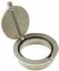
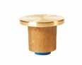
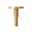
SURVEY MONUMENTS • SECTIONAL ROD MONUMENTS
ACCESS COVERS
WASHERS & NAILS
•
•
•
SUBSURFACE MAGNETICS
STAMPING TOOLS
ACCESSORIES CALL OR ORDER ONLINE! 520-622-6011 • 800-445-5320 • FAX 520-792-2030 • SURV-KAP.COM
THE
LANDMARK NAME IN SURVEY PRODUCTS Exceptional Customer Service
17|Page Lines & Points (Vol. 34: No. 3)
crews set up Bilby Towers, climbed mountains and determined positions by measuring angles and distances. During the same time period, vertical survey crews walked hundreds of thousands of kilometers measuring accurate height differences between marks using leveling rods. Below are some historical photos of survey crews on Bilby Towers and performing geodetic leveling.

In Wyoming there is a high precision traverse going East to West likely following interstate I-80 and then another going North from the first high precision traverse up to Montana. The first order triangulation surveys appear to follow major roadways. The first order leveling follows the major roadways and railways with second order leveling along smaller roadways.
Passive control has been very important in the past and will continue to be important in the future. Extensive amounts of effort and money have been put into developing these control networks that are the infrastructure for our nation’s infrastructure. The National Geodetic Survey is no longer establishing monuments and surveying them across the country, but state departments of transportation and other agencies still utilize this control for accessing the National
Season’s
Spatial Reference System and determining new survey control. Performing repeat surveys enables organizations to monitor how control is moving over time and at what rates. Soon NGS will be modernizing the NSRS and the passive control will not define the new datums but it will still be important to perpetuate passive control allowing it to be used today and in the future. While it is inevitable that some of this control will be destroyed due to roads expanding, railroads being removed and more, it is important to educate the public on the importance and purpose of these monuments so they can continue to be used by surveyors today and into the future.
 Photo 2 - Leveling down the trail into Glen Canyon. Level party of Fred E. Joeckel. Glen Canyon, Arizona. 1921. Credit: C&GS
Report Joekel 1921.7
Photo 2 - Leveling down the trail into Glen Canyon. Level party of Fred E. Joeckel. Glen Canyon, Arizona. 1921. Credit: C&GS
Report Joekel 1921.7
(Continued from Page 12) Page|18 July 2023
References:
1 Geodetic Glossary. united States, u.S. Department of Commerce, National Oceanic and Atmospheric Administration, National Ocean Service, Charting and Geodetic Services, 1986. https://repository.library.noaa. gov/view/noaa/2827/noaa_2827_DS1.pdf
2 Schwarz, Charles R.. North American Datum of 1983. united States, National Geodetic Survey, Charting and Geodetic Services, National Ocean Service, 1989. https:// geodesy.noaa.gov/PuBS_LIB/NADof1983.pdf
3 https://geodesy.noaa.gov/INFO/history/networksurveying.shtml

4 https://geodesy.noaa.gov/INFO/history/levelingnetwork.shtml
5 Zilkoski, D., Richards, J, Young, G.. Results of the General Adjustment of the North American Vertical Datum of 1988. Surveying and Land Information Systems: Journal of American Congress on Surveying and Mapping. united States, American Congress on Surveying and Mapping, Vol. 52, No. 3, 1992, pp. 133-149. https://geodesy.noaa. gov/library/pdfs/results-adjustment-navd-1988.pdf

6 https://oceanservice.noaa.gov/geodesy/bilby-towers.html
7 https://www.flickr.com/photos/ noaaphotolib/5578048172/in/album-72157635334100609/
Figure 6a - Wyoming Horizontal Network 1983
19|Page Lines & Points (Vol. 34: No. 3)
Figure 6b - Wyoming Vertical Network 1983
M E T R I C C O R N E R
Dr. Charles A. Whitten
Originally Published: ACSM Bulletin; (Washington: American Congress on Surveying and Mapping; August 1976); pp. 17 and 19.
Earlier this year Professor Herbert W. Stoughton suggested that we review some of the history of the foot/metre relationship in the u nited States. Herb referred to “the original treaty.” I thought of the International Treaty of 1875 establishing the International Bureau of Weights and Measures. Perhaps he had in mind the 1959 Administrative Order, in which the foot was redefined to bring about international accord within English-speaking nations of the world. After reviewing the actions leading to the 1875 Treaty and the 1959 Administrative Order, I thought a brief historical statement was merited, even though some of the material has been published in earlier “Metric Columns.”
In the latter part of the 18th century the English foot was the accepted standard of length by Colonial surveyors. However, even before the u.S. Coast Survey was established, Ferdinand Hassler had brought to the united States, in 1805, an iron metre bar which had been standardized in


Paris in 1796. Thus, when the Coast Survey began its work, the metre was the standard for all the measurements of length.
In 1821, John Quincy Adams submitted a “Report Upon Weights and Measures,” the first systematic consideration of the metric system by the u.S. Government. However, Congress took no action. Some 40 years later, after President Lincoln had formed the National Academy of Sciences for the purpose of advising the government on all technical matters, a committee, led by Joseph Henry, eminent physicist of the Smithsonian Institution, was appointed to reconsider weights, measures, and coinage. In 1865 this committee issued a report favorable to the adoption of the metric system. In 1866 Congress passed three metric bills. The most important of these bills legalized the use of metric weight and measures and it also specified the English equivalent. One was that one metre be equivalent to 39.37 inches.
About this same time, the French scientists who were endeavoring to maintain international agreement with respect to standards of weights and measures recognized the need to establish


877-686-8561 l www.berntsen.com
Custom Survey Markers & Monuments • Signs & Witness Posts • Flagging & Targets • Nails & Washers Custom Survey Markers & Monuments • Signs & Witness Posts • Flagging & Targets • Nails & Washers Page|20 July 2023
SURVEY MARKING
more formal procedures. In 1870 the Government of France invited the governments of the world to send delegates to Paris for the purpose of establishing an International Commission. The united States accepted the invitation, sending Joseph Henry and J.E. Hilgard of the u.S. Coast Survey as its representatives. The first meeting was held in August 1870 at Paris with 15 nations represented, but because of political complications in Europe at that time little was accomplished. At a second meeting in 1872 general plans were adopted. The most important was to make the International Metre a line measure with the material to be an alloy of 90% platinum and 10% iridium. On May 20, 1875, a formal metric convention was signed at Paris by representatives of 17 nations, the united States included, for the purpose of establishing and maintaining a permanent International Bureau of Weights and Measures.
Several years were required to produce the alloy and the different standards of weights and metre bars. It was not until 1889 that two of the two new metre bars were sent to the united States. un 1893, the Secretary of the Treasury, by administrative order, declared these new standards to be the nation’s “fundamental standards.” Because the administrative order was initiated by the
Superintendent of Weights and Measures, it has been known as the Mendenhall Order. Again, the foot/metre ratio was defined as 1200/3937.

The 1875 Treaty established the General Conference of Weight and Measures (CGPM), which meets every six years, and an International Committee of Weights and Measures, which meets every two years and which implements the recommendations of CGPM and directs the activities of the Bureau. At the 1960 meeting of CGPM - then consisting of 40 member countriesaction was taken to modernize the metric system and define the various parts of the International System of units (SI). Complete details on this and other decisions are in National Bureau of Standards Publication, 1974 Edition, the International System of units (SI) (cost, 65 cents from GPO).
The Federal Register of July 1, 1959, carries an administrative order redefining the yard as being equal to 0.9144 metre exact. This had the effect of shortening the foot by two parts in a million. However, the text of this order clearly recognizes the ratio established by the Congress (1200 / 3937) and states this ratio shall continue to be used for survey operations within the united States. In the November 1975 ACSM Bulletin Metric Corner we reproduced a statement from the Federal Register of February 3, 1975, which restates the difference between the International (English-speaking nations) Foot and the u.S. Survey Foot.
Professor Stoughton’s concern, and ours as well, is that the program chits (chips, redactor) in the hand-held computers are coded to the International Foot/Metre ratio. If the number of digits you are using is less than six, you will have no problem. But if you are using six to ten digits, two parts per million can be troublesome in checking fixed control. As we said before, “Let the Surveyor Beware!”
CD CONTAINS ENTIRE 206 PAGE M ANUAL IN BOTH “WORD” AND ADOBE “.pdf” FORMATS THAT CAN BE EDITED AND ADAPTED FOR YOUR PARTICULAR USE
Contact Secretary/Treasurer: Olian T. Shockley
Olian_Shockley@msn.com or phone 307-875-0146
by Herbert W. Stoughton
“Journeys: One Individual’s Excursions into the Surveying and Mapping Professions:
S&H)
from the sale will be invested in the PLSW Scholarship fund. Send orders to: 2821 Carey Avenue, Cheyenne,
SAFETY
SURVEYORS NOW AVAILABLE FROM THE SW CHAPTER OF PROFESSIONAL LAND SURVEYORS OF WYOMING COMPREHENSIVE,AFFORDABLE,ADAPTABLE!
Price: $30.00 (includes
Proceeds
WY 82001 ATTENTION!
MANUAL FOR
SpecialOffer - Only$50+$2SHIPPING!
21|Page Lines & Points (Vol. 34: No. 3)
The Trimble® X12 Scanning System unites the best of both worlds with industry-leading hardware and Trimble’s powerful, ultra-efficient Trimble Perspective software for guaranteed peak performance. No more complicated workflows. No complex registration process. No compromises in accuracy, speed, range, or imaging.


LEARN MORE www.frontierprecision.com/product/trimble-x12
PRODUCTS | TRAINING | REPAIR | RENTALS | TECHNICAL SERVICES Page|22 July 2023


Please Recycle
AND POINTS
BOX 8
WY 82003
LINES
P.O.
CHEYENNE,

