2 minute read
Tech-tip
Next Article

Configuring your Red Lion rate meter
These days our environment is filled with a variety of sensors and feedback systems that control the equipment we surround ourselves with. These devices feedback and control through a variety of devices, and the Red Lion range of panel meters are great additions to any control system.
This guide will walk you through configuring a Red Lion PAXR rate panel meter. Many of the parameters discussed here are relevant to the entire range of PAX meters, however we will focus on the specific configuration of these rate meters.
Dip switches
The first thing to check when setting one of these up is the dip switches located inside the plastic cover. The first three dip switches are all we need to set here.
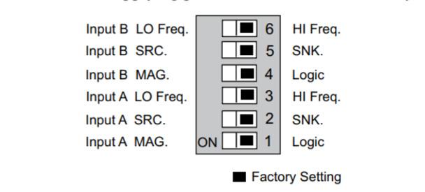
The meter has six DIP switches for input A and input B terminal set-up that must be set before applying power.
Connection
The next step is connecting your input to the panel meter. We won’t cover all the options here as there are many different possibilities, however the different input types can be viewed on page 10 of the Red Lion PAX product manual.
Parameters
Next we need to access the panel parameters, this can be done by pressing the PAR key and then using the arrow keys to navigate to the desired module, in this case module 4.
While there are many parameters available to allow you to customise your configuration, these are the primary parameters you will need to set to get your rate meter running happily.
MODULE 4
LO-UDT: The low update rate. This is how often the value on the display will be updated with the current rate value. This can be set as low as 0.1 seconds.
HI-UDT: The high update rate. This is how long the meter will ait for another pulse before setting the rate to zero. For example, on the factory settings of two seconds, the display will force to zero if it hasn’t received another pulse after two seconds, or 0.5 Hz.
The next two parameters cover scaling. If you’re happy to use the direct readout of the sensor to the display, this section is irrelevant. If you require an adjusted readout, then the two parameters you need to edit are:
rDSP1: This is the display points for the scaling output, used to determine the displayed value on the panel.
rINP1: This is the corresponding input rates that match to the display values.
For example if you set the display value to 100 and the input value to 10, then the panel will read a value between 0 and 100 for an input between 0 and 10.
