S S M E A N R S T O R S
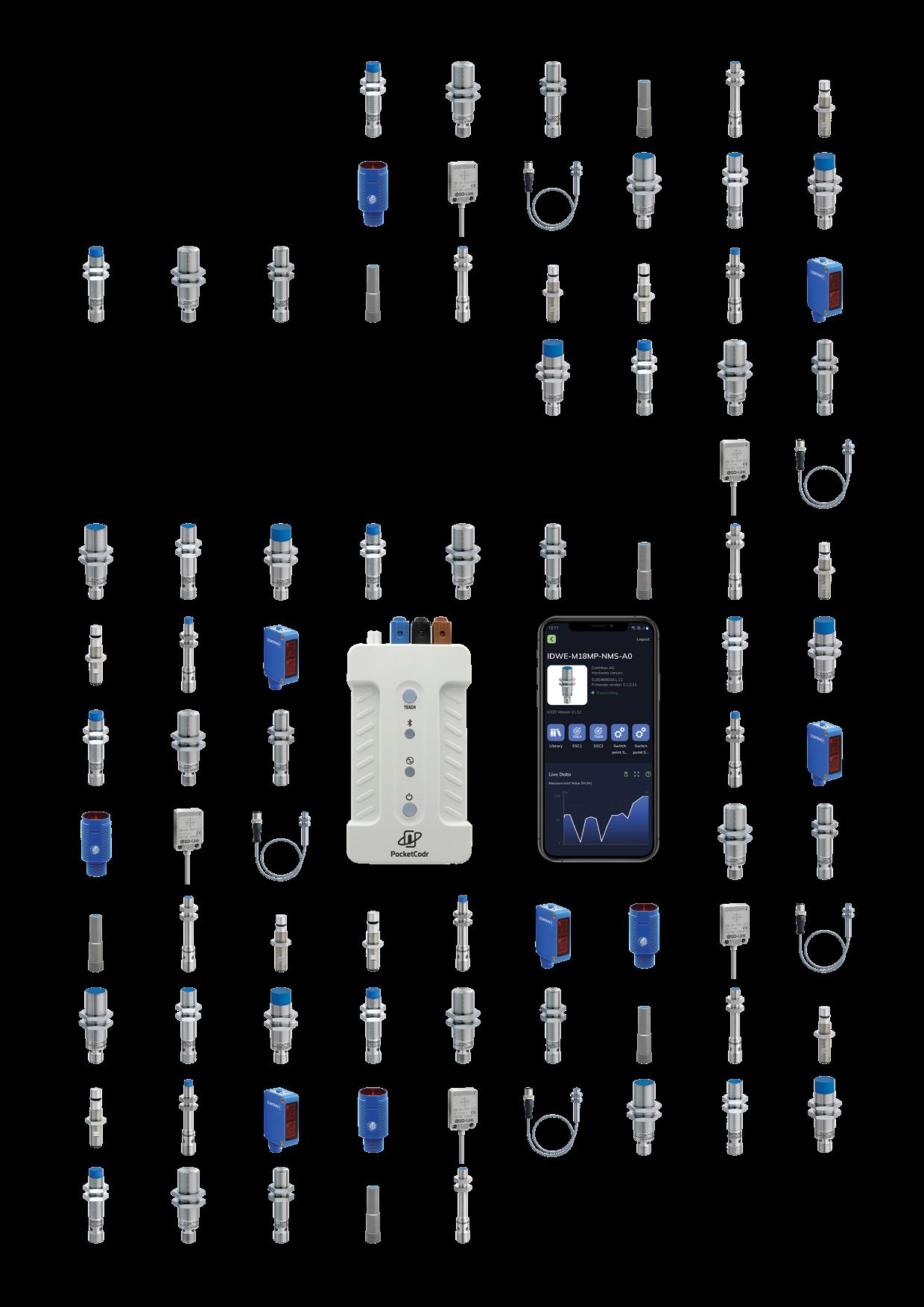
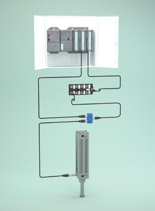
Contrinex Smart Sensors, designed with the needs of smart factories in mind, have all the answers when it comes to reducing complexity and cost. By implementing multiple sensing modes in a single sensor, Contrinex has given designers the freedom they’ve always dreamed about, offering exceptional versatility and simplified integration.
Let Contrinex
Sensors
IoT strategy; enjoy all the advantages of the industry-standard IO-Link interface, plus the option of high-speed sensor-based decision-making using SIO. The only limit is your imagination…
2 | Detailed data sheets for these products can be found on the Contrinex website: 8 7 6 5 Multi-Mode HighResolution Measurement Embedded Predictive-Maintenance Features User-Defined Memory
Smart
supercharge your
UNLOCK NEW SENSING POTENTIAL
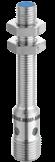
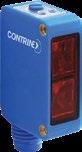
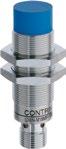
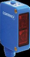
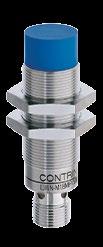
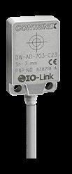
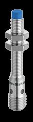
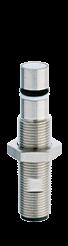
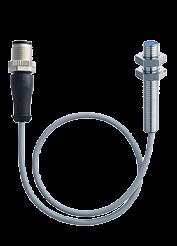
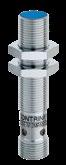
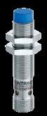
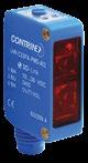
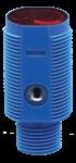
WWW.CONTRINEX.COM | 3 1 2 3 4 User-Configurable Outputs 100101 Direct Deviceto-Device Communication Dual Channel PRODUCT ADVANTAGES SMART PHOTOELECTRIC SENSORS PRODUCT ADVANTAGES SMART INDUCTIVE SENSORS 9 Multiple sensing modes in a single sensor 9 Two sensor output channels enable usage for IIoT applications 9 Extensive options for user configuration ensure exceptional versatility 9 Continual high-resolution DMS Smart Sensors measure distance to sensing targets 9 IO-Link smart profile with analog or digital output simplifies control-system integration 9 Condition-based alarms minimize maintenance costs 9 Full-inox versions offer increased protection with exceptional sensing ranges on aluminum, brass and copper targets 9 Multiple sensing modes in a single sensor 9 Two sensor output channels enable usage for IIoT applications 9 Extended measurement range vs Smart Inductive Sensors 9 Advanced switching logic encompasses more applications 9 Enhanced triple-mode teach capability for increased flexibility 9 IO-Link smart profile with digital output simplifies control-system integration 9 Condition-based self-monitoring minimizes maintenance costs 9 Localized D2D process logic enables sensor-based decision-making
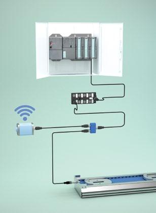
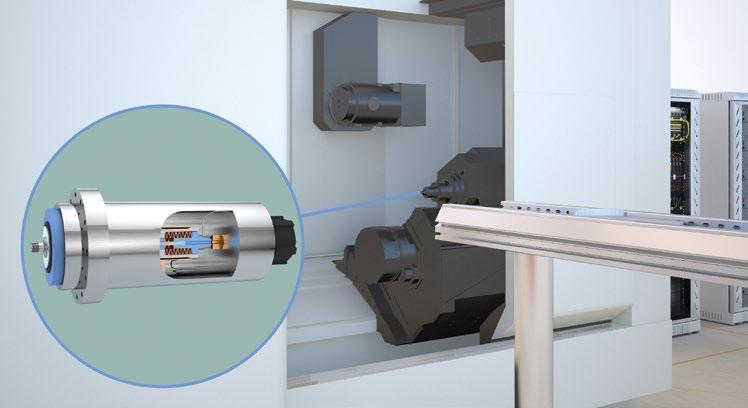
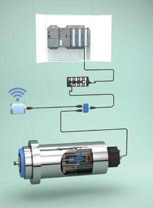
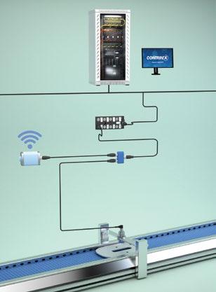
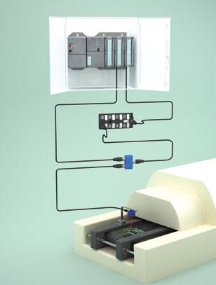
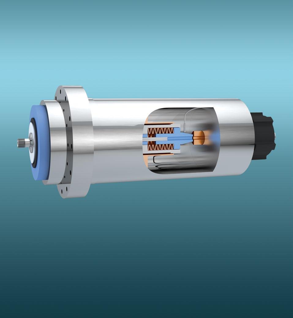
4 | Detailed data sheets for these products can be found on the Contrinex website: 1 2 An inductive DMS Smart Sensor, positioned at the end of an output conveyor, detects the presence of a component and reports to the central PLC via IO-Link, triggering a robot to transport the part to the next stage. The sensor also stores output data, reporting wirelessly to a maintenance technician. Any preventive maintenance or set-up adjustments can be actioned on a use-based schedule, rather than a time-based schedule. PRESENCE DETECTION + OUTPUT MONITORING Overall equipment effectiveness (OEE) is maximized at no additional cost 9 Prompt detection of parts at transfer station supports continuous material flow 9 Industry-standard IO-Link interface supports localized decision making 9 Smart Sensor also maintains cumulative production data in background 9 Preventive-maintenance schedule is use-based, rather than time-based An inductive DMS Smart Sensor, embedded within the spindle of a CNC machining center, senses the position of the spindle drawbar after a tool change, reporting an incomplete engagement via IO-Link to a PLC and triggering an intervention. The sensor also logs cumulative utilization data for the spindle, reporting at pre-set intervals to a process engineer via a wireless hub and enabling machine optimization to be effected in real time. POSITION SENSING + UTILIZATION REPORTING Multi-mode Smart sensor helps maximize productivity and reduce overhead costs 9 Embedded Smart sensor detects incomplete tool engagement in CNC spindle 9 Real-time IO-Link alarm inhibits machine cycle before damage occurs 9 Sensor also reports cumulative utilization data wirelessly to local process engineer 9 Machine optimization to eliminate under-utilization is effected in real time
An
The
a
from
so that set-up
a
WWW.CONTRINEX.COM | 5 3 4
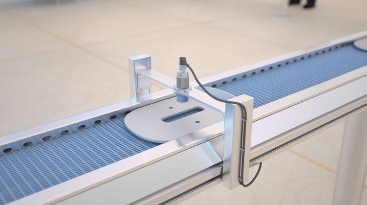
inductive DMS Smart Sensor, mounted immediately above a conveyor, measures a critical dimension on each component as it passes below the sensor, triggering an alarm if an out-of-tolerance condition is detected.
sensor also logs the cumulative measurement data and calculates the real-time deviation of the mean dimension
the norm. In the event of an unacceptable shift in the deviation, it reports wirelessly to
process engineer
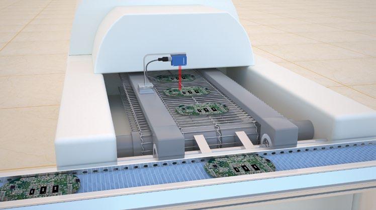
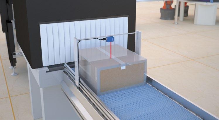
adjustments can be made before an out-of-tolerance condition arises. DIMENSIONAL MEASUREMENT + STATISTICAL ANALYSIS/REPORTING Local process engineers adjust set-up before unacceptable quality costs arise 9 High-resolution DMS Smart sensor measures critical dimension on components 9 Event-based IO-Link signal triggers alarm on detection of out-of-tolerance condition 9 Sensor also collects cumulative measurement data for real-time statistical analysis 9 Any increase of standard deviation from the norm is reported wirelessly A photoelectric DMS Smart Sensor, positioned above the output conveyor of a PCB reflow oven, detects an over- or underheight condition in a critical area of each PCB, and reports via IO-Link to a PLC, triggering an intervention if required. The sensor also logs the cumulative throughput of PCBs, and sends an SIO signal directly to the PLC when
pre-set quantity is completed, in turn triggering an upload of a new sensor configuration via IO -Link. OVER- AND UNDER-HEIGHT DETECTION + CONFIGURATION CONTROL Dynamic set-up changes are not reliant on manual intervention, reducing downtime 9 Non-contact recognition of over- or under-height PCBs eliminates downstream scrap 9 Prompt notification of defective assemblies triggers rapid local intervention 9 Cumulative-throughput data-collection allows sensor to report batchcompletions 9 Secondary SIO output triggers upload of new sensor configurations via IO-Link
OVER-HEIGHT DETECTION + THROUGHPUT MONITORING
an
the
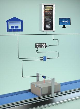
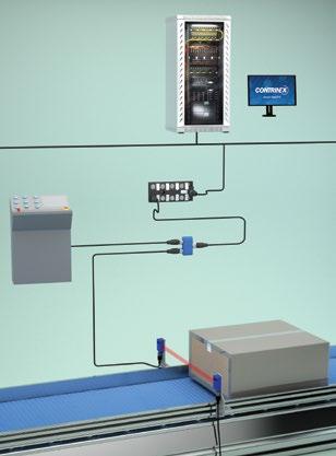
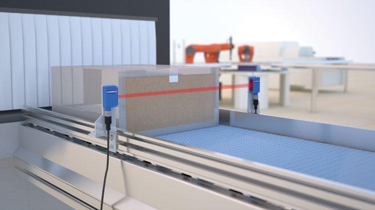
6 | Detailed data sheets for these products can be found on the Contrinex website: 5 6 A photoelectric Smart Sensor, located beside a conveyor immediately after shrink-wrapping, monitors carton throughput for stock-control purposes, reporting via IO-Link to a central server. If a pre-set period of time elapses without a carton being detected, the sensor sends a high-speed SIO signal to a local machine-controller for the next process, triggering a standby condition that reduces energy consumption. THROUGHPUT MONITORING + LOW-UTILIZATION DETECTION Dual-mode sensor minimizes energy costs during periods of low utilization 9 Smart photoelectric sensor monitors throughput for production-control purposes 9 Regular IO-Link reporting ensures real-time accuracy of inventory-control systems 9 Sensor also detects inactivity by monitoring elapsed time between detections 9 High-speed SIO signal triggers standby mode on inactive equipment, saving energy A photoelectric DMS Smart Sensor, positioned directly above a conveyor transporting sealed cartons, detects an overheight carton and reports via IO-Link to a central server, triggering an intervention if required. The sensor also maintains a count of throughput, reporting separately when a pre-set quantity is reached and sending
alert to the warehouse in preparation for the arrival of an AGV. This may also trigger an upload of path data to
AGV for its journey to a specific warehouse location.
Smart Sensor enables integration of discrete operational systems 9 Sensor with extended sensing distance ensures non-contact over-height detection 9 IO-Link communication triggers timely intervention if required 9 Smart Sensor also maintains cumulative throughput count at no extra cost 9 Secondary output alerts warehouse systems to expect arrival of an AGV
An embedded DMS inductive Smart Sensor uses inclined-plane principles to sense the precise position of the push-rod in a pneumatic cylinder, halting travel when it is fully extended. Routine process data is transmitted to the PLC via IO-Link. The sensor also monitors temperature within the cylinder and sends a high-speed SIO alarm signal directly to the PLC if an over-temperature event is detected.
9
9
(SIO) triggers rapid action
AGV POSITIONING + MACHINE OPTIMIZATION
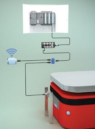
An inductive Basic Smart Sensor, positioned in the docking bay of a pick-and-place loading machine, senses the approach of an AGV and communicates via IO-Link with a central PLC, ensuring safe two-speed docking.


Using its second output, the sensor also communicates with a local control system via a wireless hub, initiating start-up for the pick-and-place machine, which has been on stand-by since completion of the previous loading cycle.

WWW.CONTRINEX.COM | 7 7 8
POSITION CONTROL + OVER-TEMPERATURE REPORTING Dual-function sensor ensures productivity is maximized at optimal cost
High-resolution position control of pneumatic cylinder ensures accurate placement 9 Real-time process data drives routine machine-position functions
Dual-channel operation allows secondary monitoring of cylinder temperature 9 High-speed serial input/output
before criticality occurs
Local optimization of machine utilization and energy usage optimizes effectiveness 9 Smart inductive sensor supports two-speed AGV docking to reduce cycle time 9 Simple IO-Link routines trigger low-speed final approach at pre-set distance 9 Secondary output communicates wirelessly with local control systems 9 Machine standby is initiated and ended based on demand, reducing energy needs

8 | Detailed data sheets for these products can be found on the Contrinex website: SMART INDUCTIVE SENSOR STANDARD PORTFOLIO SMART SENSOR BASIC SMART SENSOR DMS SMART SENSOR AMS Operating Dist. (mm) Operating Distance (mm) Operating Distance (mm) Operating Distance (mm) M8 emb. 3 3 4non emb. 4 - 6M12 emb. 4 4 6 6 non emb. 8 - 10 10 M18 emb. 8 8 10 10 non emb. 12 - 20 20 NO/NC operation Stretch, delay or one-shot timers Simple IO-Link functions Single-channel SIO or IO-Link Dual-channel configurable outputs Stretch, delay or one-shot timers Digital teach function Event-based alarms Single-channel SIO and IO-Link Dual-channel configurable outputs Stretch, delay or one-shot timers Digital teach function Event-based alarms High-resolution distance measurement Linear digital output Data Storage Pin 2 configurable as input for wire-teach or D2D Single-channel SIO and IO-Link Dual-channel configurable outputs Stretch, delay or one-shot timers Digital teach function Event-based alarms High-resolution distance measurement Linear analog or digital output Voltage or current output Data Storage Single-channel SIO and IO-Link V 1.0 or 1.1 Single Output SSP 2.7 V 1.1 / SIO Dual Output SSP 4.1.1 V 1.1 / SIO Dual Output SSP 4.1.1 V 1.1 / SIO Dual Output CURRENT USE SMART FACTORY 0..10V, 4..20mA

WWW.CONTRINEX.COM | 9 SMART PHOTOELECTRIC SENSOR STANDARD PORTFOLIO SMART SENSOR BASIC SMART SENSOR ADVANCED (COMING SOON) C23 Operating Distance (mm) Background suppression 0...300 Diffuse 0...1 5000 Reflex 0...8 000 Through beam 0...30 000 M18 Operating Distance (mm) Background suppression 0...300 Diffuse 0...1 5000 Reflex 0...8 000 Through beam 0...30 000 C23 Operating Distance (mm) Background suppression 0...300 Diffuse 0...1 5000 Reflex 0...8 000 Through beam 0...30 000 M18 Operating Distance (mm) Background suppression 0...300 Diffuse 0...1 5000 Reflex 0...8 000 Through beam 0...30 000 Light ON/Dark ON operation Stretch, and delay Dual-mode teach function Temperature monitoring Single-channel SIO and IO-Link Dual-channel configurable outputs Stretch, delay or one-shot timers Digital teach function Temperature monitoring Configurable alarm sources Event-based alarms Single-channel SIO and IO-Link V 1.0 Single/Dual Output SSP 4.1.1 V 1.1 Dual Output CURRENT USE SMART FACTORY

10 | Detailed data sheets for these products can be found on the Contrinex website: SMART INDUCTIVE SENSOR SEGMENTATION STANDARD PORTFOLIO SMART BASIC SMART DMS SMART AMS Single-channel Output Switching Signal (OSS1) on Pin 4 NO/NC operation via IO-Link or SIO 9 9 9 9 Boolean process-data variables via IO-Link User-defined thresholds trigger true/false outputs 9 9 9 9 Event counter User-defined, configurable counter modes 9 9 9 9 Signal timer Stretch, delay or one-shot timer functions 9 9 9 9 Temperature monitoring and alarms Real-time or maximum chip-temperature monitoring 9 9 9 9 Event-based diagnostics Exception reporting, including undervoltage and EMC disturbances 9 9 9 9 Advanced teach function with configurable switching distances Three teaching modes plus two teachable setpoints 9 9 9 Advanced switching logic Single-point, window and two-point (hysteresis) modes 9 9 9 Configurable alarm source(s) and threshold(s) Alarm triggered on user-defined value of any measured parameter 9 9 9 Assignment of outputs on Pin 4 and Pin 2 fully user-configurable Any Switching Signal Channel (SSC) may be assigned to either OSS1 or OSS2 9 9 9 Reserved memory space for user-defined data tags Three 32-byte locations for application, function and location tags 9 9 9 Advanced data recording and statistical analysis Configurable histogram of cumulative data values 9 9 Calibrated high-resolution distance measurement Highly accurate linear digital output 9 9 Pin 2 configurable to accept external input signal Optional SIO input allows teach-by-wire or external trigger signal 9 9 High-resolution linear analog output on Pin 2 Distance measurement with current (4-20 mA) or voltage (0-10 V) output signal 9
WWW.CONTRINEX.COM | 11 SMART PHOTOELECTRIC SENSOR SEGMENTATION STANDARD PORTFOLIO SMART BASIC SMART ADVANCED (COMING SOON) Single-channel Output Switching Signal (OSS1) on Pin 4 Light ON/Dark ON operation via IO-Link or SIO 9 9 Boolean process-data variables via IO-Link User-defined thresholds trigger true/false outputs 9 9 Event counter User-defined, configurable counter modes 9 9 Signal timer Stretch, delay or one-shot timer functions 9 9 Temperature monitoring and alarm Real-time or maximum chip-temperature monitoring 9 9 Event-based diagnostics Exception reporting, including undervoltage and EMC disturbances 9 9 User-configurable sensitivity and sequencing Three sensitivity modes plus cross-talk immunity for through-beam variants 9 9 Standard teach function via IO-Link Dual-mode teach function with single teachable setpoint 9 9 Advanced teach function with configurable switching distances Three teaching modes plus two teachable setpoints 9 Advanced switching logic Single-point, window and two-point modes 9 Configurable alarm source(s) and threshold(s) Alarm triggered on user-defined value of any measured parameter 9 Assignment of outputs on Pin 4 and Pin 2 fully user-configurable Any Switching Signal Channel (SSC) may be assigned to either OSS1 or OSS2 9 Reserved memory space for user-defined data tags Three 32-byte locations for application, function and location tags 9 Advanced data recording and statistical analysis Configurable histogram of cumulative data values Calibrated high-resolution distance measurement Highly accurate linear digital output


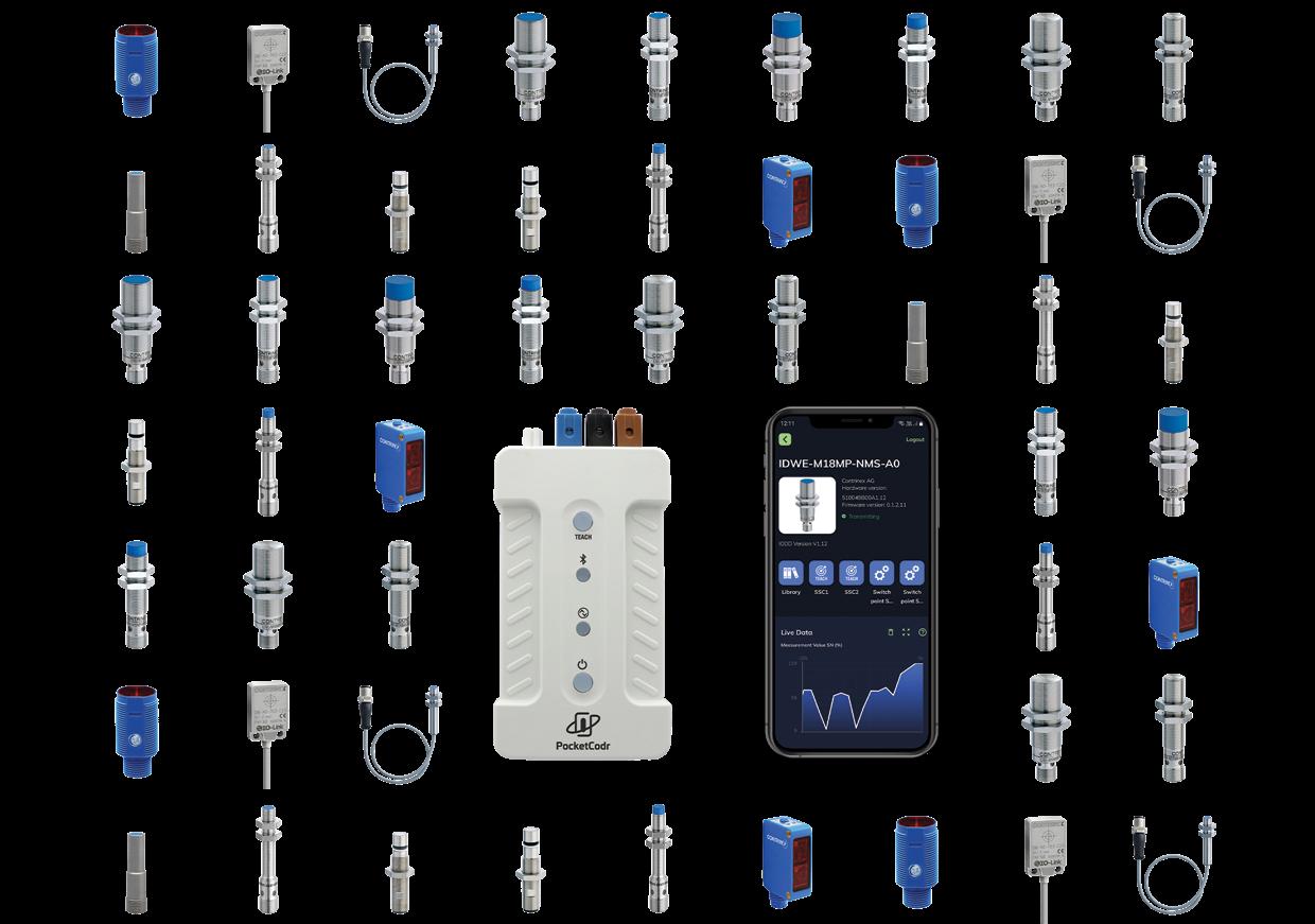
APPLICATION ENGINEER Configure sensors - Back-up configurations - Share with team members remotely Let engineers share sensor configurations remotely with technicians and other team members, keeping full control of every process in all factories across the globe. TEAM COLLABORATION PRODUCT OPERATIONS Install or replace sensors Load shared configurations to sensors Digitally teach setpoints and thresholds • Innovative PocketCodr configurator streamlines configuration and commissioning of Smart Sensors and IO-Link sensors • PocketCodr app uses live data graphs to present sensor parameters on-screen and in real time • PocketCodr’s unique Action Widgets for Contrinex Smart Sensors guide users through key configuration processes in a code-free environment • PocketCodr enables remote sharing of sensor configurations among team members, simplifying multi-site collaboration NO-CODE SENSOR CONFIGURATION 12 | Detailed data sheets for these products can be found on the Contrinex website:
LIVE
DATA GRAPHS
PocketCodr and its multi-functional companion app allow you to interact directly with sensors, presenting realtime parametric changes in-app on live data graphs. Configurable multichannel monitoring makes it easy to view either routine process data or event-driven changes of state – as and when they occur.
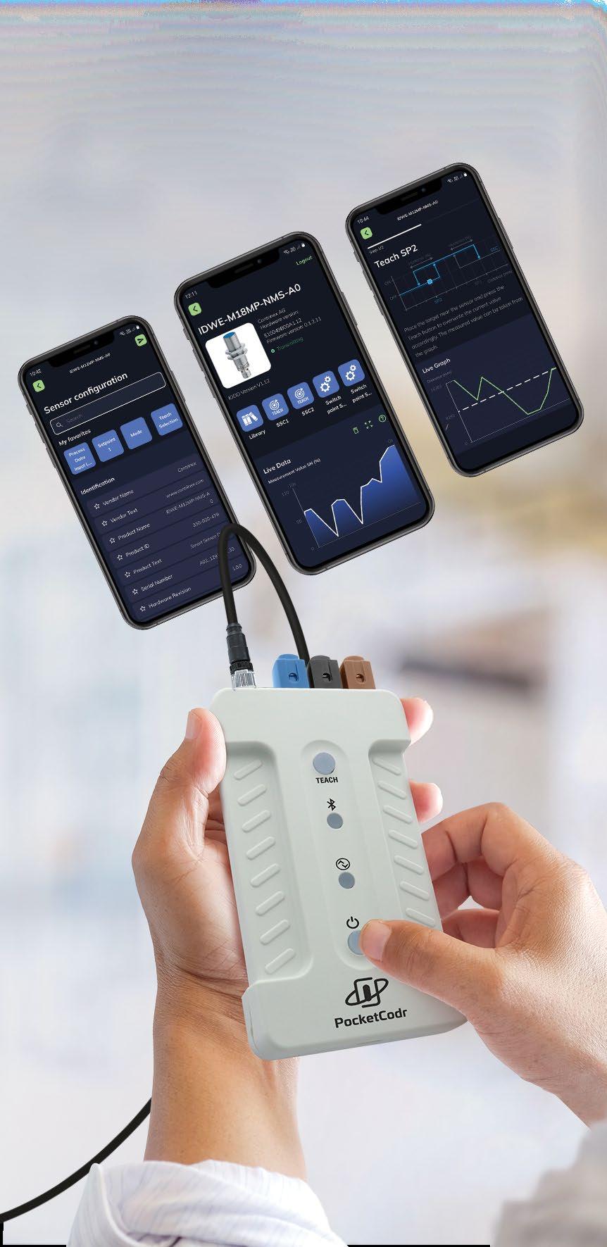
Routines for digitally teaching setpoints, setting alarm thresholds or simply viewing process data are simplified; displaying real-time target distance, switching status or timephased digital output becomes a trivial task. Simply use the Live Data Chart function with your Contrinex Smart Sensor and see exactly how your sensor is behaving – keeping the answers at your fingertips at all times.
USER-FRIENDLY ACTION WIDGETS
PocketCodr’s Action Widgets let the user configure compatible Smart Sensors without the need for programming skills.
Tapping a widget icon in the PocketCodr app initiates an easy-tounderstand configuration process, stepping through a series of intuitive, graphics-based screens. Users will find themselves at home with familiar controls that include sliders, toggle buttons, and checkboxes, with helpful prompts to guide them through the process. With PocketCodr, you can wave your programming manuals goodbye!
WWW.CONTRINEX.COM | 13
INTERACTIVE

14 | Detailed data sheets for these products can be found on the Contrinex website:
DIRECT AND INDIRECT MEASUREMENT
By adopting both direct and indirect measurement techniques, Contrinex has implemented multiple sensing modes in a single Smart Sensor. Depending on the user-defined mode of operation, measurements may be output as either process data (routine, cyclical parametric values) or event data (exceptions generated on the occurrence of a critical event).
Using the Smart Sensor’s underlying capability for highresolution distance measurement, direct measurements include axial distance (1) and lateral position (2). The sensor’s excep tional sensitivity also allows it to detect non-uniform features (for example, holes) present in a target (4).
Other physical properties whose application can be translated into a displacement are also suitable for Smart Sensing. Non-contact examples include: continuous angular measurement using a cam mounted on a rotating shaft (3), lateral position measurements of larger targets using an inclined plane surface on the target (5), force measurement using a transfer element that deforms elastically (6), as well as vibration measurement (amplitude and frequency) in the axial direction (7).
Step counting – either linear or rotational (8) – is another proven application for Smart Sensors. The sensitivity of these devices allows them to replace traditional encoders, which are often bulkier and more costly.
WWW.CONTRINEX.COM | 15 SMART FEATURES
1. Distance measurement 2. Lateral position measurement (constant distance) 3. Angular measurement 90° 270° 180° 0° 4. Feature detection 5. Lateral position measurement (inclined plane) 6. Force measurement 7. Vibration measurement 8. Step counting MULTI-MODE HIGH-RESOLUTION MEASUREMENT 9 Multiple sensing modes in a single sensor
OUTPUTS
SWITCHING SIGNAL CHANNELS (SSC)
The Smart Sensor’s internal signals are referred to as Switching Signal Channels (SSC); the external input and output signals that result from an SSC are des ignated Output Switching Signals (OSS). By default, a Smart Sensor has a single-point threshold SSC enabled on Pin 4 (OSS1) of its connector, which operates in either IO-Link mode or Standard-IO (SIO) mode. On power-up, a Smart Sensor defaults to SIO mode; once the sensor is connected to an IO-Link master, a “wake-up” pulse from the master switches it to IO-Link mode. Thereafter, bidirectional communi cation operates between the master and the sensor.
DYNAMIC SWITCHING LOGIC
When specifying Contrinex Smart Sensors, designers assign their chosen switching logic to any of the avail able sensing modes – either as a one-time choice at the time of installation, or dynamically as the equipment operating sequence dictates. A single sensor provides all the options needed to monitor multiple parameters, with the flexibility to make real-time changes over IO-Link or via the built-in Teach function.
SINGLE-POINT MODE
A second SSC may optionally be configured on Pin 2 (OSS2) of the Smart Sensor connector. If enabled, SSC2 operates solely in SIO mode and may be designated as an input or an output channel. The presence of a second IO channel gives integrators access to powerful additional features of the Smart Sensor, including Device-to-Device communication, Teach functions and Built-in Test functions.
With single-point mode selected, Smart Sensors behave as conventional two-state devices. The default logic (which may be inverted if the application requires it) sets the switching signal to “high” (SSC ON), if a threshold level or setpoint (target sensing distance, for example) has been reached. Either side of the switching point, the signal simply switches between “high” and “low” accordingly.
16 | Detailed data sheets for these products can be found on the Contrinex website: SSC SP1SSC SP1
USER CONFIGURABLE
9 Exceptional versatility optimizes spares inventory
SMART FEATURES PIN ASSIGNMENT
Window mode allows designers to monitor a range of values, which may be defined by two discrete switching setpoints. As the example shows, the default logic sets the switching signal to “high” (SSC ON) if the measured value lies between the two setpoints. In all other cases, once the measured value moves outside the defined range, the switching signal is set to “low”.
TWO-POINT (HYSTERESIS) MODE
Two-point (hysteresis) mode showcases the Smart Sen sor’s ability to respond to setpoints or threshold values that trigger a change in the SSC only when the measured value is moving in a specified direction (rising or falling). In the example shown, as the measured value falls and passes SP1, the SSC remains set to “low” (SSC OFF). Only when the measured value reaches SP2 is the SSC set to “high”. As the measured value rises again, passing SP2 has no effect on the SSC, which is only set to “low” once the measured value reaches SP1 again.
TIMING MODES
Modifying the timing of a change in the SSC allows designers to nullify the effect of common process events that give rise to false triggers. Such events include (i) momentary changes in measurement value for non-process-related reasons and (ii) momentary loss of signal for known reasons.
Delay Stretch Delay and Stretch
One shot
DELAY
Introducing a specified delay before changing the status of the OSS in either direction prevents the sensor responding to a short-duration change in measurement value for reasons that include localized variability in the environment. Adopting a switching delay also helps prevent signal “bounce”, where the transition from one state to another may not be clearly defined. Delay may optionally be combined with stretch (see below).
STRETCH
Stretching the OSS output pulse ensures that the signal has a minimum duration – often desirable for control purposes or to compensate for a measurement value that varies non-linearly over time. For example, communication with a “slow” PLC may require a minimum-duration pulse to ensure proper synchronization. Similarly, in the absence of a minimum-du ration pulse, a measurement value that is not clearly defined during the transition from one state to another might other wise give rise to multiple false triggers.
ONE-SHOT MODE
Smart Sensors also have the capability to generate a “oneshot” pulse on either the leading edge or the trailing edge of a change in the measurement value. One-shot pulses, also known as “differential up” and “differential down” may be required for secondary control functions that are imple mented in a connected PLC.
WWW.CONTRINEX.COM | 17
SSC SP2 SSC SP1 SSC SP2 SSC SP1 SSC SP2 SSC SP1 SSC SP2 SSC SP1 SSC SP2 SSC SP1 SSC SP2 SSC SP1 SSC SP2 SSC SP1 WINDOW MODE
BOOLEAN LOGIC
Designating a second SSC
to implement Boolean logic by combining an

with that of a second two-state sensor (OSS2)
presence of an aluminum-foil
BOOLEAN “AND”
Operating in Boolean “AND” mode, the signal from the secondary sensor is used to enable or disable the Smart Sensor, result ing in the Smart Sensor output (OSS1) being set to “high” only when both sensors are triggered. The output signal on OSS1 is delayed by two milliseconds.
BOOLEAN “OR”
Alternatively, when a Boolean “OR” function is required, a “high” signal from the sec ondary sensor is set to bypass the Smart Sensor signal, overwriting the SSC1 output. The Smart Sensor otherwise continues to operate normally, and consequently, its output (OSS1) is set to “high” when either sensor is triggered. Again, a two-millisec ond delay is introduced.
18 | Detailed data sheets for these products can be found on the Contrinex website: SMART FEATURES Input (OSS2/pin2) SSC1 Output (OSS1/pin4)Sensor Output disabled= 2 ms Input (OSS2/pin2) SSC1 Output (OSS1/pin4)SSC1 signal bypassed = 2 ms BOOLEAN AND (sensor enable/disable on pin 2) BOOLEAN OR (sensor bypass on pin 2)
as an input channel allows designers
internal switching signal of the Smart Sensor (SSC1) together
operating in SIO mode. In the example shown, the Smart Sensor monitors the
closure on a bottle, while the secondary photoelectric sensor checks the fill level.
100101 DIRECT DEVICETO-DEVICE COMMUNICATION 9 Localized D2D process logic enables sensor-based decision-making
Smart Sensor Photoelectric sensor
BUILT-IN
The
A
TEACH FUNCTION
FUNCTION
WWW.CONTRINEX.COM | 19 BITE (pin 2) OUTPUT (pin 4) Target detection Sensor failure Time = 2 ms = 2 ms No answer from sensor SSC SP1 SSC SP1SSC SP1 BOOLEAN XOR (BITE function on pin 2)
TEST (BITE)
SSC2 input channel serves an additional purpose when a self-test function is required. A BITE signal on SSC2 from a connected PLC or microcontroller is used (i) to determine whether the Smart Sensor is functioning correctly and (ii) to establish the presence or absence of a target.
BITE handshake pulse returned by the sensor confirms its working state, while the polarity of the pulse indicates the presence or absence of a target. Failure by the sensor to return a handshake pulse signifies a defective device. Time TEACH (pin 2) Set SP1 on pin 2 rising edge Set SP2 on pin 2 falling edge SSC SP2 SSC SP1 SSC SP2 SSC SP1 SSC SP2 SSC SP1 SSC SP1 SSC SP2 Factor y Default Step 1 Step 2 Step 3 EXTERNAL TEACH (high/low signal on pin 2)
Teaching the sensor externally to recognize one or more setpoints is another D2D function. Smart Sensors are supplied with default (factory-set) values for SP1 and SP2; during commissioning, engineers use either a locally connected teach device or a remote PLC to communicate with the Smart Sensor via OSS2. Positioning the target at the first setpoint and triggering the teach pulse sets SP1 on the rising edge of the pulse. Repo sitioning the target to the second setpoint and removing the teach pulse then sets SP2 on the falling edge of the pulse.
LOCALIZED HIGH-SPEED CONTROL
Enabling OSS2 on Pin 2 of the Smart Sensor connector gives system integrators access to localized high-speed control options; as already noted, OSS2 operates solely in SIO mode and may be designated as a input or an output channel. In addition to D2D communication, two specific advantages stand out.
REPORTING TIME-CRITICAL EVENTS
Should a remote sensor identify an out-of-range parameter that requires immediate intervention (for example, overheating), an event-based output signal is generated to notify the central control system – in the example shown, a PLC – that a system-wide shut-down is essential. In this instance, the IO-Link output (OSS1) may not respond quickly enough to prevent the problem escalating.
Using the SIO output on OSS2, the sensor delivers a high-speed notification directly to the PLC, bypassing the IO-Link channel and initiating the shut-down sequence immediately. The Smart Sensor’s dual-channel capability ensures that further, costly damage is avoided and that subsequent process down-time is minimized.
DECENTRALIZED CONTROL
Smart Sensors are also ideally suited to non-critical, decentralized process tasks under local control. In the example shown, a local SIO input signal on OSS2 enables or inhibits the operation of the sen sor without the need to route the command via the PLC. This config uration consumes little or no sys tem-wide resource, requiring only a confirmatory IO-Link signal on OSS1 to update the sensor status in due course.
With OSS2 signal alternatively con figured in output mode, the Smart Sensor may, for example, control the operation of a local sub-system, again without the need to route the command via the PLC. Using the signal to switch a simple two-state device allows the sensor to control the operation of any associated non-in telligent equipment, for example an actuator or an electrical circuit.
20 | Detailed data sheets for these products can be found on the Contrinex website: DUAL CHANNEL 9 IO-Link smart profile simplifies control-system integration 9 High-speed sensor-based decision-making using SIO
SMART FEATURES Fieldbus cable REPORTING OF TIME-CRITICAL EVENT OSS2/SIO OUTPUT REMOTE SENSING TASKS DECENTRALIZED SENSING TASK LOCAL INHIBIT CONTROL OSS2/SSC1 OSS2/SIO INPUT OSS2/SSC1 MASTER PLC Power
SAVING TIME BY DESIGN
In a fast-moving process-manufacturing environ ment, down-time is a major cost factor. While some interruptions to production are inevitable, minimizing lost time is a priority, and Smart Sensors offer big benefits here, saving time by design.
PLUG-AND-PLAY REPLACEMENT
Once initial commissioning is completed, each sensor’s configuration is stored automatically on the local IO-Link Master; this allows plug-and-play replacement of sensors should the need arise, with out any loss of functionality and without any need for recalibration. Down-time and the associated main tenance cost is kept to a minimum.
CYCLICAL AND EVENT-BASED REPORTING
The Smart Sensor’s predictive-maintenance capabilities rely on its ability to collect both process data and event data, as well as making use of its on-board cumulative-data stores. Not only can maintenance engineers monitor long-term equipment behavior, they also have confidence in the sensor’s ability to flag any one-off threshold exceptions that require attention.
THRESHOLD EXCEPTIONS
The sensor’s records cumulative data for distance, cycle count and temperature, with alarm thresholds set for each. Cumulative cycle-count limits for the expected life of the equipment being monitored are programmed into the sensor memory, and a threshold alarm is triggered when the set value is exceeded, typically via IO-Link, although a high-speed SIO output may be used instead.
In the case of distance and temperature, a single, ultimate limit for each parameter is set, and any measurement that exceeds either limit is sufficient to trigger an alarm; in this instance, a high-speed SIO signal is almost certainly the preferred option. Cumulative temperature measurements may also trigger a parametric-shift alarm, as explained below.
PARAMETRIC SHIFT
Distance
Counter Temperature
Stored measurements from a prolonged period of operation provide mainte nance engineers with a pattern of data over time; typically, the data will form a normal distribution centered around the expected mean value for the parameter in question. Examples include, but are not limited to, equipment temperature (as above) and amplitude of vibrations.
The comprehensive data patterns allow engineers to recognize any parametric shifts that occur over time. These may include a shift in the mean value, where, for example, a sustained rise in temperature occurs at a level that isn’t high enough to trigger a threshold alarm. Alternatively, an increase in the standard deviation of measurements, for example, when vibrations become unstable, may result. In either case, a parametric-shift alarm is triggered, allowing engineers to take remedial action.
WWW.CONTRINEX.COM | 21
PREDICTIVE MAINTENANCE FEATURES 9 Condition-based self-monitoring minimizes maintenance costs 9 Plug-and-play sensor replacement
SMART
USER-DEFINED MEMORY
EMBRACING THE INTERNET OF THINGS
The advent of the Internet of Things (IoT) has changed the way engi neers look at integrated processes in manufacturing and logistics. No longer do system designers con sider production lines and distri bution centers to be made up of discrete components – conveyors, actuators, motors, sensors, control lers and other similar hardware – but instead they consider more com plex Functional Units.
Working with a functional unit, the need to identify individual compo nents remains as important as ever; installing the wrong sensor could have far-reaching consequences. Contrinex Smart Sensors make it simple to get the right device in the right place, eliminating errors and avoiding costly interventions.
CUSTOMIZED SENSOR-DATA TAGS
Within each Smart Sensor, three read-write data tags are reserved for user-defined information. Designated the function tag, the location tag and the application-specific tag, respectively, they link individual sensors to specific applications or tasks, allowing process engineers to locate a discrete device quickly and easily. This simplifies installation and maintenance when more than one sensor is used in a single functional unit.
22 | Detailed data sheets for these products can be found on the Contrinex website:
9 Unique embedded sensor ID eliminates installation errors
FEATURES
TAG NAME SIZE [BYTE] EXAMPLES Function Tag 32 “Drive”, “Feed”, “Forward” Location Tag 32 “AQ3.1”, “S45-2” Application-Specific Tag 32 “end of motion”, “piston #1”, “fwd stroke”
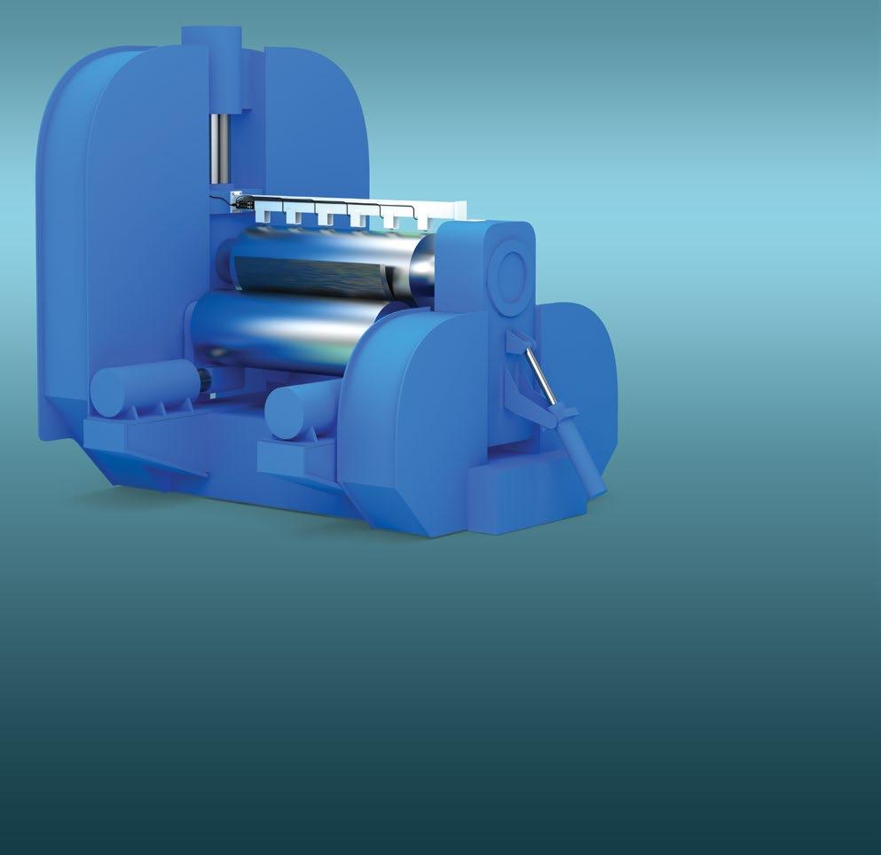
WWW.CONTRINEX.COM | 23 When bending and forming heavy steel or aluminum plates and strips, monitoring roller deformation and eccentricity is essential to avoid significant scrap costs. Taking machines out of service to inspect rollers causes unacceptable levels of downtime, driving designers to identify real-time solutions. An inductive DMS Smart Sensor from Swiss manufacturer Contrinex deliver actionable information about the condition of a roller, on demand and in real time – including during rolling operations. HEAVY MACHINERY REAL-TIME ECCENTRICITY MEASUREMENT DURING STEEL ROLLING OPERATIONS 9 Rugged inductive DMS Smart Sensors eliminate downtime, delivering actionable information about roller condition in real time 9 Availability of on-demand data removes time pressure on maintenance teams, making it possible to correct faults before product defects occur 9 V2A (AISI 303) stainless-steel M18 DMS sensors provide a robust, cost-effective solution to the problem 9 Industry-standard IO-Link connectivity enables quick, easy integration to the machine control system for process data 9 Cumulative data, including temperature and operating-cycle count, is recorded in on-board data storage 9 Individual device configurations are stored locally, allowing plug-and-play replacement of sensors when needed 9 The Smart Sensor’s dual-channel capability enables a high-speed binary SIO output to be triggered by an event-based exception 9 Proven technology ensures highly reliable fit-andforget operation with no manual intervention CUSTOMER BENEFITS Configurable dual-channel output allows high-speed event-based reporting in background Unique embedded sensor ID eliminates installation errors High-resolution measurement of radial roller displacement Sensor collects cumulative measurement data for real-time statistical analysis SMART TASKS Monitors eccentricity, temperature and operational cycle count for maintenance purposes Local storage of sensor configurations, allowing plug-andplay replacement when needed SMART TASKS
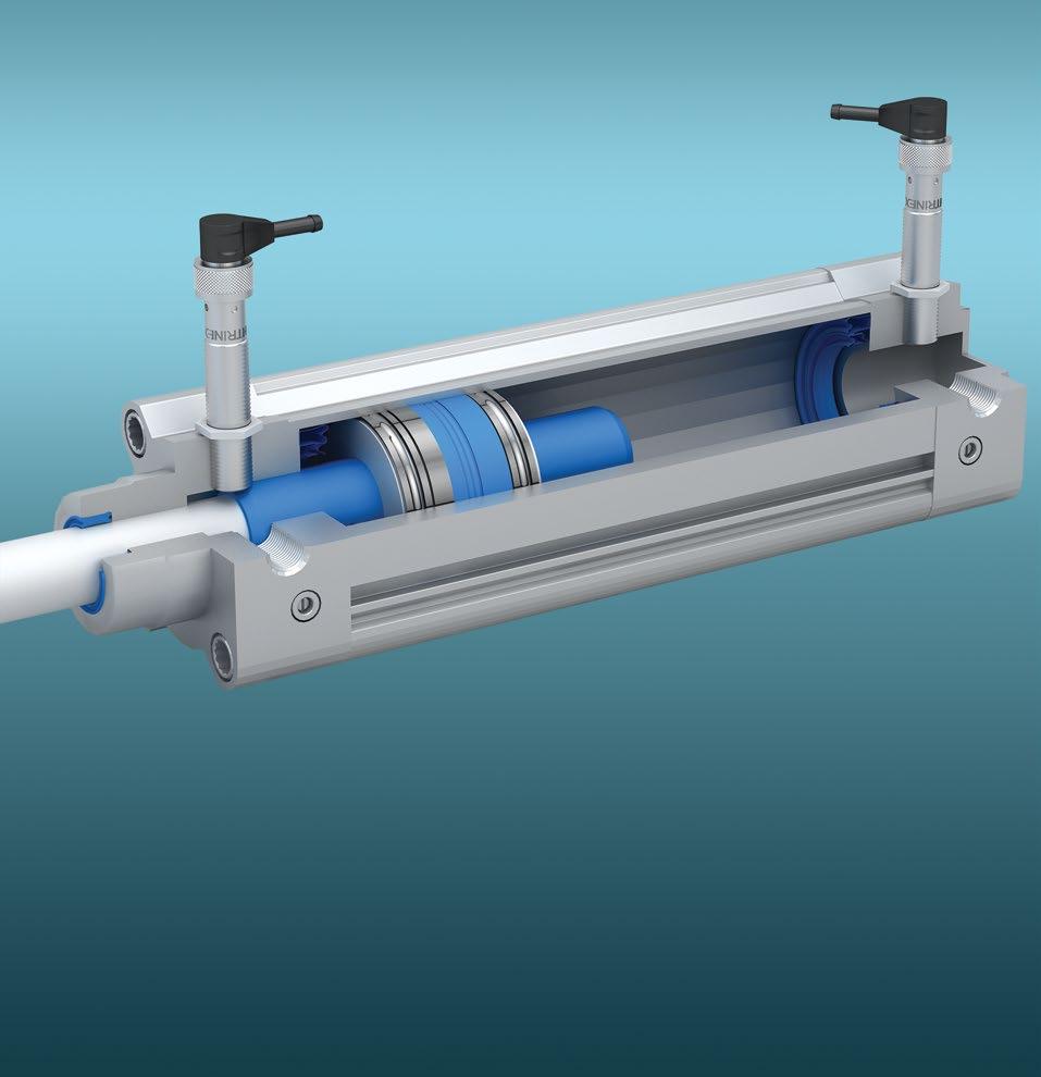
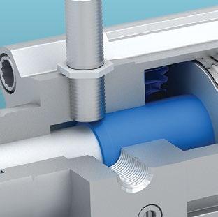
24 | Detailed data sheets for these products can be found on the Contrinex website: Industrial equipment designers continually seek ways to reduce cycle times without compromising safety or performance, and require a monitoring capability for pneumatic cylinders that identifies deviations from the optimal deceleration profile without increasing complexity or cost. Rugged, multi-mode Smart Sensors from Contrinex, embedded in each cylinder, identify adverse trends in the deceleration profile, providing a cost-ef fective, unobtrusive fit-and-forget solution. PNEUMATICS MULTI-MODE MEASUREMENT OF PISTON DISPLACEMENT AND SPEED 9 Embeddable inductive Smart Sensors offer multiple sensing modes in a single device, eliminating increased complexity and cost 9 One-shot timer feature allows process engineers to identify deviations from the optimal deceleration profile, minimizing maintenance expense 9 Dual-channel capability enables a local alarm to be triggered by an event-based exception, avoiding a plant-wide shut-down 9 Industry-standard IO-Link connectivity provides a single interface to the machine control system 9 Cumulative operating data for predictive maintenance, including temperature and operating-cycle count, is recorded in on-board data storage 9 Sensor configurations are stored locally, allowing plug-and-play replacement of sensors when needed 9 Proven technology ensures highly reliable fit-and-forget operation with no manual intervention CUSTOMER BENEFITS SMART TASKS High-resolution measurement of lateral piston displacement Repeated high-speed displacement measurement at timed intervals High-speed communication with central control system for timecritical events Monitor temperature, vibration and process cycle count for maintenance purposes Local storage of sensor configurations, allowing plug-andplay replacement when needed Generation of velocity gradient using on-board cumulative data store SMART TASKS
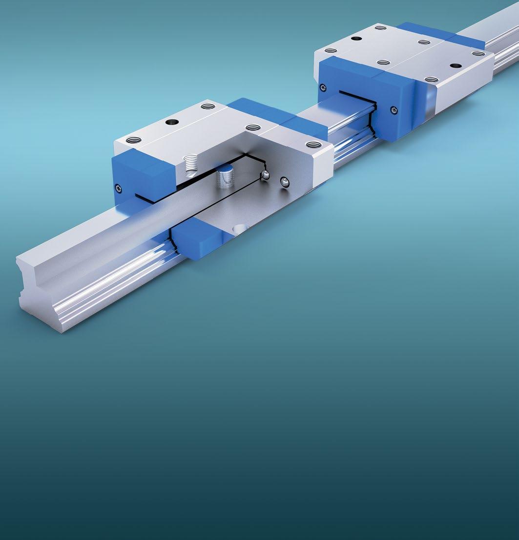
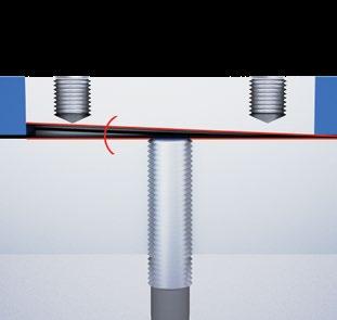
WWW.CONTRINEX.COM | 25 Automation engineers designing high-speed assembly equipment with multiple linear transfers between workstations need to maximize speed and accuracy while keeping cost down. They require a single-sensor positional-control solution that delivers a high-speed approach to the critical areas and a slower, high-precision final positioning. An inductive Smart Sensor from Contrinex with IO-Link connectivity and multiple user-configurable outputs performs both the required tasks in a highly cost-effective manner. LINEAR GUIDE PERFECT LOCATION AND POSITIONING OF LINEAR STAGE 9 Rugged inductive Smart Sensors ensure accurate positioning of linear stages without compromising operational speed 9 Single-sensor positional-control system is non-complex and highly affordable 9 Compact embeddable M12 sensors fit unobtrusively and easily into off-the-shelf linear guide rails 9 Industry-standard IO-Link connectivity provides a single interface to the machine control system 9 Sensor configurations are stored locally, allowing plugand-play replacement of sensors when needed 9 Proven technology ensures highly reliable fit-and-forget operation with no manual intervention CUSTOMER BENEFITS Reliable position sensing on high-speed approach High-accuracy lateral position measurement during final stage positioning Sensor configuration is backed-up automatically on the local IO-Link Master IO-Link smart profile simplifies controlsystem integration Unique embedded sensor ID eliminates installation errors User-configured setpoints ensure precise window-mode positioning SMART TASKS
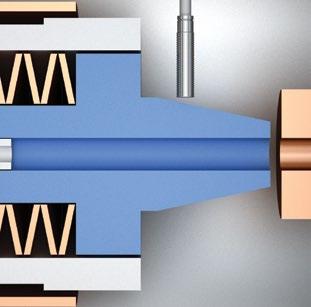
26 | Detailed data sheets for these products can be found on the Contrinex website: Modern CNC machining centers cope with ranges of materials, workpieces and cutting speeds that require different tool characteristics; spindles with automatic tool-changing are key to optimizing throughput. If a new tool fails to engage completely, damage to the tool, the workpiece or the spindle results. Smart Sensors from Contrinex, embedded in the body of the spindle, monitor the position of the drawbar during changes; any non-compliant measurements stop the process, triggering an alarm. SPINDLE CHECKING TOOL PRESENCE AND POSITION IN A CONFINED SPACE 100101 Precision real-time measurement of drawbar position Threshold alarms identify overtemperature and end of service life Sensor configuration is backed-up automatically on the local IO-Link Master Self-test function guards against sensor failure User-configured setpoints ensure accurate end-of-travel position sensing High-speed notification of timecritical events 9 Embeddable inductive Smart Sensor monitors drawbar position, detecting incomplete tool engagement and inhibiting further motion before damage occurs 9 Single-sensor positional-control system is non-complex and highly affordable 9 Embeddable M12 sensor fits snugly in the limited space available 9 Industry-standard IO-Link connectivity provides a single interface to the machine control system 9 Cumulative operating data for predictive maintenance, including temperature and operating-cycle count, is recorded in on-board data storage 9 Sensor configurations are stored locally, allowing plug-and-play replacement of sensors when needed 9 Proven technology ensures highly reliable fit-andforget operation with no manual intervention. CUSTOMER BENEFITS SMART TASKS SMART TASKS
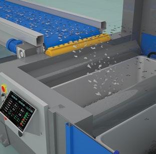

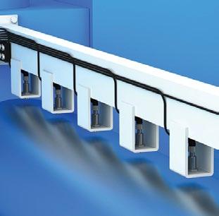
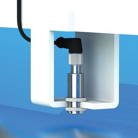
WWW.CONTRINEX.COM | 27 The global recycling industry continually seeks to reduce the cost of sorting and separating mixed-metal scrap. With the introduction of induction sorting, designers require sensors that operate accurately and at high speed to identify and separate fast-moving streams of ferrous and non-ferrous material in a single pass. Rugged inductive Smart Sensors from Contrinex, embedded immediately below the delivery belt, provide continuous high-speed detection across the full width of a conveyor. RECYCLING RELIABLE DETECTION OF DIFFERENT METALLIC MATERIALS 9 Embeddable inductive Smart Sensors detect ferrous and non-ferrous metal and trigger separation accurately and reliably 9 A single array of sensors provides continuous detection across the full width of a conveyor 9 Smart Sensors are easily able to identify material on fast-moving conveyors 9 Industry-standard IO-Link connectivity provides a single interface to the machine control system 9 Cumulative operating data for predictive maintenance, including temperature and operating-cycle count, is recorded in on-board data storage 9 Sensor configurations are stored locally, allowing plugand-play replacement of sensors when needed 9 Proven technology ensures highly reliable fit-and-forget operation with no manual intervention CUSTOMER BENEFITS Unique embedded sensor ID eliminates installation error High-speed localized communication with air-knife actuators Multi-mode target recognition at constant target distance Cumulative cycle/target counting in each of two modes Threshold alarms identify overtemperature and end of service life Sensor configuration is backed-up automatically on the local IO-Link Master SMART TASKS
Terms of delivery and right to change design reserved. We attempt to ensure that the information in this brochure is accurate, however, this information may contain technical errors, typographical errors, and inaccuracies. We reserve the right to correct these errors and decline any liability in relation with this brochure. Furthermore, the smart factory use cases described in this brochure are for illustrative purposes only, we decline any liability related the feasibility or efficiency gains of these example cases applied to real applications. © CONTRINEX AG 2022 900-310-002 – 11.22 – 1000 HEADQUARTERS CONTRINEX AG Industrial Electronics Route du Pâqui 3 – PO Box – CH-1720 Corminboeuf Switzerland Tel: +41 26 460 46 46 – Fax: +41 26 460 46 40 Internet: www.contrinex.com – E-mail: info@contrinex.com MULTI-MODE HIGH-RESOLUTION MEASUREMENT EMBEDDED PREDICTIVEMAINTENANCE FEATURES USER-DEFINED MEMORY 100101 DIRECT DEVICE-TO-DEVICE COMMUNICATION DUAL CHANNELUSER-CONFIGURABLE OUTPUTS BITETEMPERATUREONE SHOTSTRETCHDELAY DETECTION COUNTER
