partnership providing innovative mining products and services collaborative delivery model value-added products and services, including:
A partnership providing innovative mining products and services
A partnership providing innovative mining products and services

A collaborative delivery model of value-added products and services, including:
A collaborative delivery model of value-added products and services, including:
Mill linings
Mill linings
Mill linings
Wear resistant liners
Wear resistant liners
Wear resistant liners
Conveyor components
Conveyor components
Conveyor components

Screening and filtering solutions
Screening and filtering solutions
Screening and filtering solutions
Trommels
Trommels
Trommels
Hydrocyclones
Hydrocyclones
Hydrocyclones
Water cutting services
Water cutting services
Water cutting services
The DYNAMAX range of mill liners offers optimum mill lining endurance and reliability
The DYNAMAX range of mill liners offers optimum mill lining endurance and reliability
The DYNAMAX range of mill liners offers optimum mill lining endurance and reliability


SPILLEX
SPILLEX
SPILLEX


Conveyor for the environmental
Conveyor for the environmental

Conveyor skirt for the ultimate environmental

VOLUME 123 NO. 8 AUGUST 2023
info@tegaindustries.co.za www.tegaindustries.com
YOUR MILL
UNLOCK
CAPACITY
CONTINUOUS EFFICIENT MAXIMISED GRINDING
Increase Asset Productivity
partnership providing innovative mining products and services
A partnership providing innovative mining products and services
A partnership providing innovative mining products and services

collaborative delivery model value-added products and services, including:
A collaborative delivery model of value-added products and services, including:
A collaborative delivery model of value-added products and services, including:
Mill linings
Mill linings
Mill linings
Wear resistant liners
Wear resistant liners
Wear resistant liners
Conveyor components
Conveyor components
Conveyor components

Screening and filtering solutions
Screening and filtering solutions
Screening and filtering solutions
Trommels
Trommels
Trommels
Hydrocyclones
Hydrocyclones
Hydrocyclones
Water cutting services
Water cutting services
Water cutting services
Reduce Risk
Environmental Sustainability
Reduce Operating Expenses
Improve Safety
The DYNAMAX range of mill liners offers optimum mill lining endurance and reliability info@tegaindustries.co.za
The DYNAMAX range of mill liners offers optimum mill lining endurance and reliability
The DYNAMAX range of mill liners offers optimum mill lining endurance and reliability


SPILLEX
SPILLEX
SPILLEX


Conveyor skirt for the ultimate environmental
Conveyor for the environmental
Conveyor for the environmental
www.tegaindustries.com
The Southern African Institute of Mining and Metallurgy
OFFICE BEARERS AND COUNCIL FOR THE 2022/2023 SESSION
Honorary President
Nolitha Fakude
President, Minerals Council South Africa
Honorary Vice Presidents
Gwede Mantashe
Minister of Mineral Resources and Energy, South Africa
Ebrahim Patel
Minister of Trade, Industry and Competition, South Africa
Blade Nzimande
Minister of Higher Education, Science and Technology, South Africa
President
Z. Botha
President Elect
W.C. Joughin
Senior Vice President
E. Matinde
Junior Vice President
G.R. Lane
Incoming Junior Vice President
T.M. Mmola
Immediate Past President
I.J. Geldenhuys
Honorary Treasurer
W.C. Joughin
Ordinary Members on Council
W. Broodryk G. Njowa
Z. Fakhraei S.J. Ntsoelengoe
R.M.S. Falcon (by invitation) S.M. Rupprecht
B. Genc M.H. Solomon
K.M. Letsoalo A.J.S. Spearing
S.B. Madolo A.T. van Zyl
F.T. Manyanga E.J. Walls
M.C. Munroe
Co-opted to Members
K. Mosebi
A.S. Nhleko
Past Presidents Serving on Council
N.A. Barcza C. Musingwini
R.D. Beck S. Ndlovu
J.R. Dixon J.L. Porter
V.G. Duke M.H. Rogers
R.T. Jones D.A.J. Ross-Watt
A.S. Macfarlane G.L. Smith
M.I. Mthenjane W.H. van Niekerk
G.R. Lane–TPC Mining Chairperson
Z. Botha–TPC Metallurgy Chairperson
M.A. Mello–YPC Chairperson
K.W. Banda–YPC Vice Chairperson
Branch Chairpersons
Botswana Being established
DRC Not active
Johannesburg N. Rampersad
Namibia Vacant
Northern Cape I. Tlhapi
North West I. Tshabalala
Pretoria Vacant
Western Cape A.B. Nesbitt
Zambia J.P.C. Mutambo (Interim Chairperson)
Zimbabwe A.T. Chinhava
Zululand C.W. Mienie
PAST PRESIDENTS
* W. Bettel (1894–1895)
* A.F. Crosse (1895–1896)
* W.R. Feldtmann (1896–1897)
* C. Butters (1897–1898)
* J. Loevy (1898–1899)
* J.R. Williams (1899–1903)
* S.H. Pearce (1903–1904)
* W.A. Caldecott (1904–1905)
* W. Cullen (1905–1906)
* E.H. Johnson (1906–1907)
* J. Yates (1907–1908)
* R.G. Bevington (1908–1909)
* A. McA. Johnston (1909–1910)
* J. Moir (1910–1911)
* C.B. Saner (1911–1912)
* W.R. Dowling (1912–1913)
* A. Richardson (1913–1914)
* G.H. Stanley (1914–1915)
* J.E. Thomas (1915–1916)
* J.A. Wilkinson (1916–1917)
* G. Hildick-Smith (1917–1918)
* H.S. Meyer (1918–1919)
* J. Gray (1919–1920)
* J. Chilton (1920–1921)
* F. Wartenweiler (1921–1922)
* G.A. Watermeyer (1922–1923)
* F.W. Watson (1923–1924)
* C.J. Gray (1924–1925)
* H.A. White (1925–1926)
* H.R. Adam (1926–1927)
* Sir Robert Kotze (1927–1928)
* J.A. Woodburn (1928–1929)
* H. Pirow (1929–1930)
* J. Henderson (1930–1931)
* A. King (1931–1932)
* V. Nimmo-Dewar (1932–1933)
* P.N. Lategan (1933–1934)
* E.C. Ranson (1934–1935)
* R.A. Flugge-De-Smidt (1935–1936)
* T.K. Prentice (1936–1937)
* R.S.G. Stokes (1937–1938)
* P.E. Hall (1938–1939)
* E.H.A. Joseph (1939–1940)
* J.H. Dobson (1940–1941)
* Theo Meyer (1941–1942)
* John V. Muller (1942–1943)
* C. Biccard Jeppe (1943–1944)
* P.J. Louis Bok (1944–1945)
* J.T. McIntyre (1945–1946)
* M. Falcon (1946–1947)
* A. Clemens (1947–1948)
* F.G. Hill (1948–1949)
* O.A.E. Jackson (1949–1950)
* W.E. Gooday (1950–1951)
* C.J. Irving (1951–1952)
* D.D. Stitt (1952–1953)
* M.C.G. Meyer (1953–1954)
* L.A. Bushell (1954–1955)
* H. Britten (1955–1956)
* Wm. Bleloch (1956–1957)
* H. Simon (1957–1958)
* M. Barcza (1958–1959)
* R.J. Adamson (1959–1960)
* W.S. Findlay (1960–1961)
* D.G. Maxwell (1961–1962)
* J. de V. Lambrechts (1962–1963)
* J.F. Reid (1963–1964)
* D.M. Jamieson (1964–1965)
* H.E. Cross (1965–1966)
* D. Gordon Jones (1966–1967)
* P. Lambooy (1967–1968)
* R.C.J. Goode (1968–1969)
* J.K.E. Douglas (1969–1970)
* V.C. Robinson (1970–1971)
* D.D. Howat (1971–1972)
* J.P. Hugo (1972–1973)
* P.W.J. van Rensburg (1973–1974)
* R.P. Plewman (1974–1975)
* R.E. Robinson (1975–1976)
* M.D.G. Salamon (1976–1977)
* P.A. Von Wielligh (1977–1978)
* M.G. Atmore (1978–1979)
* D.A. Viljoen (1979–1980)
* P.R. Jochens (1980–1981)
* G.Y. Nisbet (1981–1982)
A.N. Brown (1982–1983)
* R.P. King (1983–1984)
J.D. Austin (1984–1985)
* H.E. James (1985–1986)
H. Wagner (1986–1987)
* B.C. Alberts (1987–1988)
* C.E. Fivaz (1988–1989)
* O.K.H. Steffen (1989–1990)
* H.G. Mosenthal (1990–1991)
R.D. Beck (1991–1992)
* J.P. Hoffman (1992–1993)
* H. Scott-Russell (1993–1994)
J.A. Cruise (1994–1995)
D.A.J. Ross-Watt (1995–1996)
N.A. Barcza (1996–1997)
* R.P. Mohring (1997–1998)
J.R. Dixon (1998–1999)
M.H. Rogers (1999–2000)
L.A. Cramer (2000–2001)
* A.A.B. Douglas (2001–2002)
S.J. Ramokgopa (2002-2003)
T.R. Stacey (2003–2004)
F.M.G. Egerton (2004–2005)
W.H. van Niekerk (2005–2006)
R.P.H. Willis (2006–2007)
R.G.B. Pickering (2007–2008)
A.M. Garbers-Craig (2008–2009)
J.C. Ngoma (2009–2010)
G.V.R. Landman (2010–2011)
J.N. van der Merwe (2011–2012)
G.L. Smith (2012–2013)
M. Dworzanowski (2013–2014)
J.L. Porter (2014–2015)
R.T. Jones (2015–2016)
C. Musingwini (2016–2017)
S. Ndlovu (2017–2018)
A.S. Macfarlane (2018–2019)
M.I. Mthenjane (2019–2020)
V.G. Duke (2020–2021)
I.J. Geldenhuys (2021–2022)
Honorary Legal Advisers M H Attorneys Auditors Genesis Chartered Accountants Secretaries The Southern African Institute of Mining and Metallurgy 7th Floor, Rosebank Towers, 19 Biermann Avenue, Rosebank, 2196 PostNet Suite #212,
2132 E-mail: journal@saimm.co.za
*Deceased
Private Bag X31, Saxonwold,
Editorial Board
S.O. Bada
R.D. Beck
P. den Hoed
I.M. Dikgwatlhe
R. Dimitrakopolous*
B. Genc
R Hassanalizadeh
R.T. Jones
W.C. Joughin
A.J. Kinghorn
D.E.P. Klenam
J. Lake
H.M. Lodewijks
D.F. Malan
R. Mitra*
H. Möller
C. Musingwini
S. Ndlovu
P.N. Neingo
S.S. Nyoni
M. Phasha
P. Pistorius
P. Radcliffe
N. Rampersad
Q.G. Reynolds
I. Robinson
S.M. Rupprecht
K.C. Sole
A.J.S. Spearing*
T.R. Stacey
E. Topal*
D. Tudor*
D. Vogt*
*International Advisory Board members
Editor /Chairperson of the Editorial Board
R.M.S. Falcon
Typeset and Published by The Southern African Institute of Mining and Metallurgy

PostNet Suite #212
Private Bag X31
Saxonwold, 2132
E-mail: journal@saimm.co.za
Printed by Camera Press, Johannesburg
Advertising Representative
Barbara Spence
Avenue Advertising
Telephone (011) 463-7940
E-mail: barbara@avenue.co.za

ISSN 2225-6253 (print)
ISSN 2411-9717 (online)
Contents
Journal Comment: To use/accept or not to use/accept AI, that is the question! by R.M.S. Falcon iv President’s Corner: Facilitated Goodbyes The ‘Adjourning’ Phase by Z.
Botha
PROFESSIONAL TECHNICAL AND SCIENTIFIC PAPERS
Thermal decomposition of carbonate minerals as pre-treatment in the production of ferromanganese alloys reduces the energy requirement for smelting and can reduce greenhouse gas emissions. A kinetic model for the thermal decomposition of manganese ores is presented based on adaptation of kinetic data for the decomposition of manganese oxides and calcium carbonate. The model was validated against thermogravimetric data for two carbonaceous manganese ore samples and one ferruginous manganese ore sample.
v-vi
Directory of Open Access Journals


THE INSTITUTE, AS A BODY, IS NOT RESPONSIBLE FOR THE STATEMENTS AND OPINIONS ADVANCED IN ANY OF ITS PUBLICATIONS.
Copyright© 2023 by The Southern African Institute of Mining and Metallurgy. All rights reserved. Multiple copying of the contents of this publication or parts thereof without permission is in breach of copyright, but permission is hereby given for the copying of titles and abstracts of papers and names of authors. Permission to copy illustrations and short extracts from the text of individual contributions is usually given upon written application to the Institute, provided that the source (and where appropriate, the copyright) is acknowledged. Apart from any fair dealing for the purposes of review or criticism under The Copyright Act no. 98, 1978, Section 12, of the Republic of South Africa, a single copy of an article may be supplied by a library for the purposes of research or private study. No part of this publication may be reproduced, stored in a retrieval system, or transmitted in any form or by any means without the prior permission of the publishers. Multiple copying of the contents of the publication without permission is always illegal.
U.S. Copyright Law applicable to users In the U.S.A. The appearance of the statement of copyright at the bottom of the first page of an article appearing in this journal indicates that the copyright holder consents to the making of copies of the article for personal or internal use. This consent is given on condition that the copier pays the stated fee for each copy of a paper beyond that permitted by Section 107 or 108 of the U.S. Copyright Law. The fee is to be paid through the Copyright Clearance Center, Inc., Operations Center, P.O. Box 765, Schenectady, New York 12301, U.S.A. This consent does not extend to other kinds of copying, such as copying for general distribution, for advertising or promotional purposes, for creating new collective works, or for resale.
▶ ii AUGUST 2023 VOLUME 123 The Journal of the Southern African Institute of Mining and Metallurgy
VOLUME 123 NO. 8 AUGUST 2023
The thermal decomposition kinetics of carbonaceous and ferruginous manganese ores in atmospheric conditions by S.A.C. Hockaday, F. Dinter, and Q.G. Reynolds 391
Mechanical activation and physicochemical factors controlling pyrometallurgical, hydrometallurgical, and electrometallurgical processing of titanium ore: A review by
H.C.S. Subasinghe and A.S. Ratnayake ............................................
399
Ilmenite is the leading global titanium feedstock used to produce refined TiO2. Mechanical grinding may enhance process efficiency and product quality by decreasing the activation energy of chemical reactions, leading to lower processing time and energy consumption. The significance of mechanical activation in pyrometallurgical, hydrometallurgical, and electrometallurgical processing of ilmenite is reviewed.
Removal of arsenic and metal ions from acidic effluents via the Fenton reaction method by
Y. Wang
Arsenic-bearing acidic effluents from hydrometallurgical processes contain many harmful metal ions and must be treated before discharge to ensure environmental compatibility. This study examined the co-precipitation of arsenic, copper, zinc, aluminium, and magnesium using the Fenton reaction. The stability of the precipitate was assessed by the toxicity characteristic leaching test. With the exception of Mg, all elements were removed at pH 5–6 and an H2O2/As mole ratio of 2 at ambient temperature. The precipitate proved effective in fixing arsenic.
Mechanism and control of deformation in gob-side entry with thick and hard roof strata by J.S. Guo, L.Q. Ma, and I. Ngo
Deformation of gob-side entries is critical to ensure stability in longwall coal mines. The characteristics and mechanisms of deformation during retreat of a longwall face are addressed. The primary cause of deformation is identified and a mitigating deformation control method proposed. Simulation results demonstrate significant reductions in roof stress and deformation of the gob-side entry. These findings provide guidance for effectively managing deformation in gob-side entries, particularly when dealing with thick and hard roof strata.
415
423
The Journal of the Southern African Institute of Mining and Metallurgy VOLUME 123 AUGUST 2023 iii ◀
Journal Comment
Copper Cobalt
There is much interest in the fast-developing field of Artificial Intelligence (AI), and more particularly ChatGPT, in all sectors of the economy, not the least in education, editing, and publishing. A recent webinar presented by four informed speakers and hosted by ASSAf outlined some important issues, all of which are highly pertinent to the activities in our Institute. Most particularly, this would be of relevance for our Journal and the papers published therein. A few key points are outlined below, which I hope will lead to a discussion with respect to the way forward in developing the SAIMM’s Editorial Board’s (Publication Committee’s) future policy in this regard.
Of greatest significance is the fact that, while AI in the form of ChatGPT is fun, it is not an author! In the words of the publishers of Nature, while there may be a place for it in due course, it still has problems and will not meet the requirements of publishing norms today. The challenges include the facts that it cannot provide accuracy or interpretations and explanations, it cannot be held accountable, nor can it ensure data privacy. Furthermore, it takes information or ‘learns’ from previously published data and may therefore be biased in its output. It does not have the capacity to evaluate the information so extracted. In other words, input affects output.
What AI can do with the ‘tools’ now available is background research in an extensive and thorough manner, incorporating data from all sources taken from all levels and from different qualities of papers. In such cases it is necessary to recognize that the information so derived may be biased and that, more significantly, it cannot be defended. Who is accountable for such output? Thus, while AI is useful in communicating science it may not be able to contextualize the information. It may also be adept at summarizing data for lay audiences, but it could use unreviewed material and thereby provide misinformation. AI can improve the detection of plagiarism and manipulation of illustrations.
For these reasons, AI is useful in the early stages of research. It can write an article, write purpose statements, retrieve associated references, and obtain information from the literature. Furthermore, it can analyse results.
But such abilities also raise questions.

Can reviewers use AI to peer review a paper and then use the outcome as their own work? This is not possible due to the depth of evaluation required as such tasks require human interpretation.
Can AI be considered a co-author when paired with genuine human authors? I have had sight of such a paper submitted to another journal, and wondered what our Editorial Board would do in such a case. A team of publishing editors agreed that AI could not be considered an author as it cannot meet the rules and requirements of journals.

The answers to date have been that all authors must be active, responsible, reliable, and able to defend their stance or statement, which humans can do but AI cannot. The recommendation in this instance is for AI to be cited in the acknowledgements, with a clear explanation as to its role in the paper. However, this is not always followed. Papers are being submitted with the bulk of the work produced by AI. The validity of such a paper without clear definition of the role played by AI is unacceptable.
Questions are now being asked as to whether there are guard rails to protect against such practices. Authors are asked to take responsibility and adopt ‘best practice’; namely, to practice and clearly show transparency and accountability.
All this leads to the ultimate question: Does AI diminish scholarly publishing? The discussions continue
R.M.S. Falcon
▶ iv AUGUST 2023 VOLUME 123 The Journal of the Southern African Institute of Mining and Metallurgy
To use/accept or not to use/accept AI, that is the question!
President’s Corner
Facilitated Goodbyes The ‘Adjourning’ Phase

How to say goodbye? Working in the projects environment, I am familiar with ‘projects’ that have a very specific time limit. I know at some point in time, they must end. My time as the President of the SAIMM is no different. This was a year of learning, of achievements, of meeting incredible people, and of beautiful change. Therefore, it is extremely difficult to say goodbye. During this time of handing over, I was reminded of the work done by Bruce Tuckman. He looked at the ‘Developmental Sequence in Small Groups’, which describes the path that teams follow on their way to high performance.
Usually, a high-performing team comprises excellent leaders. They say the definition of a good leader is that when the leader is no longer in the room, the team still carries on without any upset. How does a good leader enable and empower their team to be a high-performing team, whether they are present or not?
On one of my mega projects, I was privileged to have a Project Manager that was invested in relationships and our team journey. He initiated a team journey, with specific activities, to support each of the phases described by Bruce Tuckman. The work I’m referencing, was the work of, and presented by, Karien van der Merwe (The Thrive Institute, Work Psychologist, specializing in group dynamics) and was facilitated by her as well.

It goes without saying that the various activities during the team journey, from ‘Forming’ to being a high-performance team (‘Performing’), shown in Figure 1, enabled our very successful adjourning.

Nonetheless, I want to focus on specific activities that supports the ‘Adjourning’ phase. During this phase, there are members leaving the team, there are feelings of extreme uncertainty, there are responsibilities that shift and handovers that need to happen (Figure 2). It is important to facilitate the disconnection/disengagement of individuals during this time. Facilitated goodbyes, in the form of farewell functions, sessions where team members celebrate and share their learning, and voice appreciation and thanks to each other for the contributions they made in each other’s work-lifejourneys, ensures more effective re-engagement on the next project and with future teams. Closure guarantees future engagement in a new environment.
All the change happening in the ‘Adjourning’ phase requires resilience from team members, and to build resilience we focused on celebrating, on highlighting accomplishments, on recognition (of both teams and individuals), and maybe the most important of all, we focused on lessons learned that we could take into the future (Figure 3).
The Journal of the Southern African Institute of Mining and Metallurgy VOLUME 123 AUGUST 2023 v ◀
Figure 1
President’s Corner (continued)


I can, again, declare that the SAIMM is truly a family that supports transition and growth. During our year together the SAIMM family celebrated a new SAIMM podcast, a new student initiative, participation of more than 48 countries in our events, more than R3 million in sponsorship from our industry, and many, many more achievements.
And then, finally, a very big celebration of our new President, William Joughin. He believes that our assets are our people. He is a very concise, technical leader, who believes in knowledge and learning. He believes in empowerment, providing guidance and enabling learning. He has a hope for us, to keep growing and to develop our industry and technology. I am extremely excited to keep serving this year, under the guidance of William Joughin.
Z. Botha President, SAIMM
▶ vi AUGUST 2023 VOLUME 123 The Journal of the Southern African Institute of Mining and Metallurgy
Figure 2 – Typical behaviour during the ‘Adjourning’ phase
Figure 3 – Typical activities to support the team during the ‘Adjourning’ phase
Affiliation:
1Western Australia School of Mines, Curtin University, Australia.
2Department of Mechanical and Mechatronic Engineering, University, Stellenbosch, South Africa.

3Department of Process Engineering, Stellenbosch University, South Africa.
4 Extractive Metallurgy Division, Mintek, South Africa.
Correspondence to: L. Hockaday
Email: lina.hockaday@curtin.edu.au
Dates:
Received: 14 Dec. 2022
Revised: 3 Jul. 2023
Accepted: 10 Aug. 2023
Published: August 2023
How to cite:
Hockaday, S.A.C., Dinter, F., and Reynolds, Q.G. 2023
The thermal decomposition kinetics of carbonaceous and ferruginous manganese ores in atmospheric conditions.
Journal of the Southern African Institute of Mining and Metallurgy, vol. 123, no. 8. pp. 391–398
DOI ID: http://dx.doi.org/10.17159/24119717/2527/2023
ORCID: L. Hockaday https://orcid.org/0000-0003-2597-9756
The thermal decomposition kinetics of carbonaceous and ferruginous manganese ores in atmospheric conditions
by S.A.C. Hockaday1,2, F. Dinter2, and Q.G. Reynolds3,4
Synopsis
The thermal decomposition of carbonate minerals as pre-treatment before smelting reduces the energy requirement for smelting. It can also make the combustion of fossil fuels for heating unnecassary. Thermal decomposition may become important in reducing greenhouse gas emissions when producing ferromanganese alloys while simultaneously reducing electrical energy demand during smelting. A kinetic reaction rate model for the thermal decomposition of manganese ores is presented, based on published reaction rate kinetics for the decomposition of manganese oxides and calcium carbonate. The model was validated against thermogravimetric data for two carbonaceous manganese ore samples and one ferruginous manganese ore sample. The reaction rate model shows that carbonate minerals in the manganese ores are decomposed at temperatures above 900 °C while pyrolusite is decomposed at temperatures from 450 °C to 500 °C. Mn2O3 decomposes rapidly at 550 °C. Braunite decomposition at temperatures below 1000 °C was negligible. The presence of organic carbon in the samples led to further reduction of the samples during thermal treatment.
Keywords
manganese ore, pre-treatment, thermal decomposition, reaction rate modelling.
Introduction
Manganese ores have complex mineralogy (Chetty, 2008). Although most South African manganese ores manganese oxides such as pyrolusite, bixbyite, braunite and hausmannite, they are often associated with gangue minerals such as calcite, kutnahorite, ankerite and dolomite. These carbonate minerals undergo endothermic decomposition reactions that increase the energy demand for ferromanganese alloy production. In contrast, the higher manganese oxides undergo mainly exothermic reduction reactions with solid carbon and carbon monoxide, which are desirable in smelting as they reduce the overall energy demand of the process. Pre-treatment methods for manganese ores may be categorized as pre-heating, calcination, or agglomeration.
Pre-heating has been practised to reduce the electricity demand of ferromanganese submerged arc furnaces (Tanabe, 1968; Ishak and Tangstad, 2007; Tangstad, Ichihara and Ringdalen, 2015) by using combustion of fossil fuels or furnace off-gas to pre-heat the feed. This practice has inspired more research into the pre-heating and pre-reduction of manganese ores not just with furnace off-gas, but also with biocarbon and indirect use of solar thermal energy (Hockaday et al., 2020; Mckechnie, McGregor and Venter, 2020; Hamuyuni et al., 2021; Julia et al., 2021; Kazdal et al., 2021).
Calcination is generally not practised as feed preparation for ferroalloy production due to the requirements for strong lumpy ore as the solid burden in a submerged arc furnace. The solid burden in the furnace acts similarly to that in a vertical kiln; it is heated and reduced by carbon monoxide evolved from the reduction of MnO to metallic manganese in the coke bed (Olsen, Tangstad and Lindstad, 2007). However, the advantages of such preheating have been evaluated and it was found that preheating carbonate-rich manganese ores may reduce the electric energy demand for ferroalloy production by 25% for cooled thermally treated ore and by 35 % for hot charged thermally treated ore (Serov, 2007).
Currently, sintering is the leading pre-treatment technology for manganese ores. Sintering is used to agglomerate fines (<6 mm) into furnace feed. Although not traditionally seen as a reducing process, sintering is done in reducing conditions with solid carbon as the reductant at temperatures of 1200°C or above (Pienaar and Smith, 1992; Daavittila et al., 2001). Although sintering decomposes carbonate minerals, it also reduces the manganese oxides to hausmannite and manganosite leading to a trade-off where sintered
391 The Journal of the Southern African Institute of Mining and Metallurgy VOLUME 123 AUGUST 2023
The thermal decomposition kinetics of carbonaceous and ferruginous manganese ores
products require less energy for carbonate decomposition during smelting but lose the benefit of energy from exothermic manganese reduction reactions (Broekman and Ford, 2004) under smelting conditions. The use of physical separation techniques such as dense media separation or flotation to upgrade manganese ores by removing gangue minerals such as silica or calcite has not been widely applied as the success of these methods is dependent on the mineralogy of the ores. Ore samples evaluated for this paper show finely intergrown structures even on the 20 µm scale (Hockaday et al., 2021), making upgrading by physical separation methods impractical due to the fine particle size required to fully liberate the gangue minerals. The successful use of dense medium separation has been described (Pienaar and Smith, 1992) for Mamatwan ore, but the results may not be replicable on other ores with finely intergrown minerals. The evaluation of physical separation as an alternative or complementary beneficiation method for manganese ores is outside the scope of this paper.
The question then arises if it is possible to decompose the carbonate minerals while preventing or hindering the reduction of the oxide minerals? Less reliance on the use of fossil fuels for heating, lowering of the energy demand for smelting and avoidance of the Boudouard reaction during smelting to avoid increased reductant demand are three reasons for a thermal pre-treatment step in oxidative conditions. We developed a reaction rate model describing the behaviour of the ores for thermal treatment under atmospheric conditions. The model will be useful in further investigations of manganese ore pre-treatment in oxidizing conditions using renewable energy sources such as electricity from renewables or direct concentrating solar thermal treatment to achieve the required temperatures. This makes developing a nonreducing thermal pre-treatment for manganese ores a promising route for greener ferromanganese production.
Theory
Thermal pre-treatment has been recommended for carbonaceous manganese ores (Serov, 2007) in Russia using furnace off-gas for pre-heating and pre-reduction. The thermal decomposition reactions for the carbonate minerals are:
temperatures. Although most South African ores have lower concentrations of carbonate minerals than the Russian ores, the benefits of decomposing the carbonates before smelting are clear, especially for the ores containing dolomite.
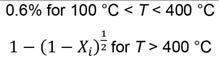
The thermal decomposition of CaCO3 has been studied (Hills, 1968; Ar and Doğu, 2001; Halikia et al., 2001) due to its importance in cement production. The rate-limiting step has been determined as either the chemical reaction at the interface (Ar and Doğu, 2001; Halikia et al., 2001) or heat and mass transfer (Hills, 1968). The decomposition rate of different CaCO3 sources may vary significantly (Ar and Doğu, 2001), so it is important to validate the kinetic rate expression against measured data. For this study, the calcination reactions are assumed to be limited by the contracting area mechanism (Halikia et al., 2001), with the integrated rate equation expressed as

where Xi is the conversion extent of reaction i, t is the time, and ki is the reaction rate frequency factor, dependent on temperature according to the Arrhenius equation,


with Ai the pre-exponential factor, Eai the activation energy, T the temperature in Kelvin and R the universal gas constant.
Manganese oxides can also decompose thermally in air. The reactions are as follows
Since the composition of kutnahorite, Ca(Mn, Mg)(CO3)2, is stoichiometrically variable, the decomposition of kutnahorite was modelled as a combination of Equations [1], [2], and [3]. This enables the modelling of ores with high variability in mineralogy.
These reactions are endothermic as seen from the positive enthalpy of the reaction, ∆H. Enthalpy values were obtained from the HSC Reaction module (Roine and Bjorklund, 2002; Outotec, 2019) at standard conditions of 25°C and 1 atmosphere. Avoiding these reactions inside the smelter reduces the energy demand for smelting, increasing the smelter’s productivity. If these carbonate minerals decompose inside the smelter, the released carbon dioxide may react with solid carbon according to the Boudouard Equation [4]:
This leads to increased reductant consumption inside the furnace and higher energy demand to maintain smelting
The reaction kinetics of reaction Equations [7] and [8] has been studied (Terayama and Ikeda, 1983) and found to be limited by interfacial chemical reaction. Further studies on reaction kinetics for reaction Equation [8] were done to investigate using manganese oxides as a redox pair for water splitting (Botas et al., 2012; Alonso, Gallo and Galleguillos, 2016) and the contracting volume mechanism was found to describe the data well, although the nth order mechanism was found to improve the model fit.
The thermal decomposition of Mn7SiO12, Equation [9], has been reported (Grimsley, See and King, 1977) as occurring above 900°C, but no published studies were found on the kinetics of this reaction. For this study, the manganese oxide decomposition reactions will be assumed to be limited by the contracting volume mechanism (Terayama and Ikeda, 1983), with the integrated rate equation expressed as
Manganese ores may contain some hydrated minerals, and the mass loss at temperatures below 300°C is expected to be from the evaporation of surface water or the dewatering of hydrated minerals.
The manganese ore samples was found to contained significant amounts of organic carbon, up to 3% by weight. The organic carbon source is unknown but may be from the untreated ore (plant or biomatter) or from contamination at the smelter site (from reductant).
392 AUGUST 2023 VOLUME 123 The Journal of the Southern African Institute of Mining and Metallurgy
[1] [2] [3]
[4]
[5]
[6]
[7] [8] [9]
[10]
The thermal decomposition kinetics of carbonaceous and ferruginous manganese ores
The organic carbon content was modelled as pure graphite in this study. The kinetics of the direct reduction of manganese ore pellets containing carbon has been studied (Zhang and Xue, 2013), and a kinetic model in two stages was proposed. The earlier stage proceeds with carbon as a reducing agent and the kinetic expression for a contracting volume as applied to the non-isothermal method according to Equation [10]. This reaction rate was applied to the possible reduction reactions simultaneously. The later stage regarding reduction reactions with carbon monoxide was neglected as the sample mass loss was fully explained by reduction with solid carbon. The reactions with solid carbon considered in this study are:
Experimental methodology
The ore samples obtained from the Transalloys ferromanganese smelter in South Africa were characterized by chemical analysis and mineralogical method. The fines were screened from the fresh ore − these are usually briquetted with dust and metal fines before smelting (Steenkamp et al., 2018). Chemical analysis was done by inductively coupled plasma discharge optical emission spectroscopy (ICPOES). The carbonate content was determined from the difference between total carbon and organic carbon by combustion analysis. The mineralogy of the ores was investigated by X-ray diffraction analysis and scanning electron microscopy. More details on the sample mineralogy are reported elsewhere (Hockaday, 2023, Chapter 3) as the focus of this paper was on the reaction kinetics modelling. Cryptomelane (KMn8O16) was expressed in manganese oxide form as [18]
to simplify the decomposition of the ore while maintaining the oxidation state of manganese.


After reconciling the chemical analysis and mineralogical data, the compositions of the ore samples are reported in Table I.
These compositions took into account the thermal behaviour of the samples as well, as the high-cryptomelane ore (CMN) showed faster carbonate decomposition than the high braunite ore (BMN), which was captured by expressing Mg content as MgCO3 rather than CaMg(CO3)2. Since the tests were done in triplicate and this behaviour was consistent for the ore in all three tests, it was included in the model. This does not imply that the mineralogical analysis was in error, but rather that decomposition of the carbonate minerals occurred differently in the two ores investigated. This is
393 The Journal of the Southern African Institute of Mining and Metallurgy VOLUME 123 AUGUST 2023
[11] [12] [13] [14] [15] [16] [17]
Table I
Ferruginous Mn ore (FMN) High-braunite Mn ore (BMN) High-cryptomelane Mn ore (CMN) MnO2 17.81 2.56 17.08 Mn7SiO12 14.78 41.74 27.02 Mn2O3 0.83 0.84 1.85 Mn3O4 – 7.19 7.87 SiO2 13.58 3.42 6.21 Fe2O3 31.94 6.18 6.87 K2O 1.62 0.05 1.10 Cr2O3 0.08 0.51 –P2OY5 0.09 0.06 0.07 BaSO4 0.40 0.37 0.30 Na2O 0.55 0.03 0.21 Organic carbon, C 3.44 1.78 1.92 CaMg(CO3)2 – 17.61CaCO3 – 16.48 20.00 CaO 1.76 – 1.68 MgO 0.66 – –Mn2O3.3H2O 1.89 0.09 0.72 Al2O3 10.57 – –Al2O3.3H2O – 1.09 0.98 MgCO3 – – 6.12
Composition of three manganese ore samples (wt.%)
The thermal decomposition kinetics of carbonaceous and ferruginous manganese ores
most likely due to mineralogical differences outside of the scope of the current study, and which indicate that more in-depth research is required into the mechanisms of thermal decomposition as related to carbonate gangue minerals in manganese ores. For now, this study concluded that thermogravimetric studies should be included in the characterization of ores where different carbonate minerals are present and the thermal decomposition behaviour needs to be accurately modelled even at lower temperatures (300–800°C).
Experimental set-up
The non-isothermal tests were done at Mintek’s high-temperature test facilities in Randburg, South Africa. The tests were done using an electrically heated tube furnace with a recrystallized alumina tube of 50 mm internal diameter. A Eurotherm thyristor-coupled controller, connected to a B-type thermocouple suspended just above the sample, controlled the furnace temperature. The sample was placed in an alumina crucible and raised into the furnace on an alumina pedestal and rod resting on a digital electronic balance. The balance and sample were moved with a hydraulic hoisting mechanism.
Weight loss was recorded on a personal computer interfaced with the balance. Milled samples were treated in the furnace at a ramp rate of 4°C per minute up to 1000 °C in air. The calcined products were not tested, as the study looked at the mass loss of the sample as representative of the changes in the minerals. However, other studies looking at the behaviour of these ores when heated directly with concentrating solar radiation or in a muffle furnace report analyses of the products (Hockaday et al., 2018, 2019, 2021; Hockaday, 2023).
Reaction rate model methodology
Three samples from each ore were treated in the thermogravimetric furnace, and the recorded mass loss curves were used to inform the reaction rate model describing the thermal behaviour. The rate equations were fitted to one of the three sets of experimental data. Figure 1 shows the measured sample mass of a ferruginous Mn ore (FMN) sample and the predicted sample mass from a model based on published reaction rate parameters and the model with parameters fitted to the measured data. Since the ferruginous sample did not contain carbonate minerals, the reactions evaluated were the thermal decomposition of MnO2 to Mn2O3 and Mn2O3 to Mn3O4 and the reduction reactions with solid carbon (Equations [11] − [17]).
The resulting reaction rate equations were then used in an HSC simulation with the measured temperature profiles of the remaining two tests for the ore sample as input to estimate the samples' mass loss as output for one-minute intervals. The plots of the modelled sample mass against the measured sample mass validated the


model for that specific ore. Figure 2 shows the validation for the ferruginous ore model with the modelled sample mass within 2% of the measured sample mass for both validation tests.


The parameters fitted with the ferruginous ore were transferred to the high braunite and high-cryptomelane ores models. The measured sample mass of the high-braunite ore was used to fit parameters for the thermal decomposition of dolomite and calcite (Equations [1] and [2]). The measured values and modelled values are shown in Figure 3.
The validation for the high braunite Mn ore (BMN) is shown in Figure 4. The BMN model reflects the slower decomposition of CaCO3 in the high braunite ore with an activation energy of 190 kJ/ mol compared to the published value of 155 kJ/mol (Halikia et al., 2001). The modelled values are within 4 % of the measured values for the first validation test and within 2% of the measured values for the second test.
The mass loss for the high-cryptomelane ore was used to estimate the thermal decomposition of MgCO3 and confirm the calcite decomposition rate. The measured and modelled sample mass values are shown in Figure 5.
394 AUGUST 2023 VOLUME 123 The Journal of the Southern African Institute of Mining and Metallurgy
Figure 1—Ferruginous ore measured and modelled mass loss with measured temperature
Figure 2—Model validation for ferruginous ore reaction rates by comparison of modelled and measured sample mass values
Figure 3—High braunite ore measured and modelled sample mass with measured temperature profile
Figure 4—Model validation for high braunite ore reaction rates by comparison of modelled and measured mass loss values
The thermal decomposition kinetics of carbonaceous and ferruginous manganese ores
The validation results for the high-cryptomelane ore (CMN) are shown in Figure 6. The modelled sample mass remained within 2% of the measured sample mass. The CMN model showed faster decomposition of CaCO3 than the high braunite ore with an activation energy of 175 kJ/mol. The difference in calcite decomposition rates for different ore samples is not unexpected, as even high-purity calcites have been shown to vary greatly in decomposition behaviour (Ar and Doğu, 2001).


The kinetic rate equations, activation energies, and preexponential factors determined from the experiments are summarized in Table II.
Results and discussion
The developed models were used to estimate the sample composition during heating. The normalized content of manganese compounds and organic carbon (modelled as pure graphite, C) during the thermal treatment (at a heating rate of 4°C/min up to 1000°C) is shown for the ferruginous Mn ore in Figure 7. For clarity, the reduction of iron oxides has not been shown, but iron oxides were reduced simultaneously with the manganese oxides while carbon was present in the system to a final mixture of Fe3O4 (18.8 wt.%) and FeO (8.2 wt.%) with some Fe2O3 (3.5 wt.%) and Fe (2.2 wt.%).


The decomposition and reduction of MnO2 and Mn2O3 were complete by 500°C and 550°C, respectively. Reduction of Mn3O4 and Mn7SiO12 continued while solid carbon was present in the system. Similarly, the normalized compositions of manganese compounds, carbonate minerals, and organic carbon during thermal treatment for the high-braunite ore are shown in Figure 8.
Table II
Since the braunite ore has a very low content of MnO2 and Mn2O3, mass loss can be attributed mainly to the reduction of braunite (Mn7SiO12) and the thermal decomposition of carbonate minerals modelled as dolomite (CaMg(CO3)2) and calcite (CaCO3). Calcite decomposition only started at around 850 °C, indicating that calcination temperatures of at least 900°C are required to achieve full calcination of this ore.
Reaction rate equations, activation energies and pre-exponential factors determined from experimental data
Reaction Rate equation Reference proposing rate equation


395 The Journal of the Southern African Institute of Mining and Metallurgy VOLUME 123 AUGUST 2023
Figure 5—High cryptomelane ore measured and modelled sample mass with measured temperature profile
Figure 6—Model validation for high cryptomelane ore reaction rates by comparison of modelled and measured mass loss values
kJ/mol Ai [1] [2] –Halikia et al. (2001) 165 190 (BMN) 175 (CMN) 4 368 805 4 368 805 [3] –––165 (CMN) 4 368 805 [7] [8] Terayama and Ikeda (1983) 62.6 65.5 23 426 100 4 072 865 [11] to [17] Zhang and Xue, (2013) 18.0 0.00038
Eai
Figure 7—Modelled ferruginous manganese ore compositional changes during thermal treatment
Figure 8—Modelled high-braunite ore compositional changes during thermal treatment
The thermal decomposition kinetics of carbonaceous and ferruginous manganese ores
The normalized compositions of manganese compounds, carbonate minerals, and organic carbon during thermal treatment for the high cryptomelane ore are shown in Figure 9.
The cryptomelane ore has a higher content of oxidized manganese compounds and, similar to the ferruginous ore, the decomposition and reduction of MnO2 and Mn2O3 were complete by 500°C and 550°C respectively. The decomposition of calcite in this ore started at around 720 °C, and full calcination was reached at 950°C. The reduction of braunite and Mn2O3 continued while solid carbon was available in the system resulting in 11.6 wt% of MnO in the treated sample.

From the results, the thermal decomposition of MnO2 and Mn2O3 will always be completed before the calcination of the ores, and cannot be limited by choice of operational temperature without impacting the degree of calcination. The reduction of all manganese oxides will start even at 350°C but may be limited by the amount of solid carbon available. This is illustrated for the two carbonate-rich ores in Figures 10 and 11, where scenarios without organic carbon in the ore are compared to the ores as received. It may also be seen that this strategy would be more effective for the high-braunite ore, as braunite did not thermally decompose over the temperature range investigated.

The calculated composition of the three ores after thermal pretreatment is given in Table III.

Significant amounts of braunite (Mn7SiO12) and hausmannite (Mn3O4) remain after the thermal treatment. These compounds will react with carbon monoxide during smelting according to the following reactions,
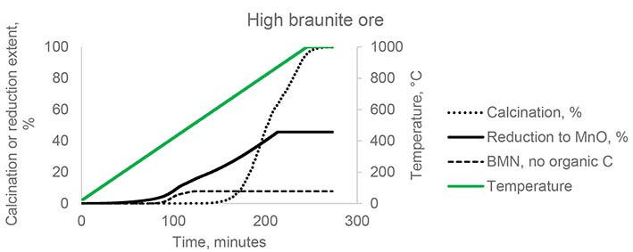
Table III
Modelled composition of thermally treated ores based on composition in Table I
Modelled thermally treated composition
These exothermic reactions will result in reduced energy demand during smelting compared to manganese sinter, which has been fully reduced to MnO.
The thermally pre-treated material can be introduced as feed to briquetting plants or agglomerated with low-temperature binders (Devasahayam, 2018) to achieve the strength requirements of blast furnaces or submerged arc furnaces during high-carbon ferromanganese production.
The specific energy requirement (SER) to produce a highcarbon ferromanganese alloy (78% Mn, 7.5%C, remainder Fe) at 1300°C, slag at 1500°C, and off-gas at 700°C, was estimated based on an HSC distribution model with carbon addition of twice the stoichiometric requirement and assumptions based on published literature (Broekman and Ford, 2004). For untreated high-braunite ore, the SER was calculated as 2.31 MW/t alloy produced. After oxidative thermal treatment, the SER was calculated as 0.98 MW/t alloy produced. This is a reduction of electricity demand of more than 50%. Since the South African national grid is supplied by mainly coal fired power plants, the reduction in scope 2 emissions is similarly significant. Compared to a sinter produced from this material (assuming MnO/Mn2O3 mass ratio in the sinter of 0.42 (Daavittila et al., 2001)), the sinter SER was calculated as 1.21 MW/t alloy. For this ore, thermal pre-treatment results in a product with an SER lower than that for sinter, with 0.36 t carbon dioxide emissions less per ton of product.
396 AUGUST 2023 VOLUME 123 The Journal of the Southern African Institute of Mining and Metallurgy
[19] [20]
Figure 9— Modelled cryptomelane ore compositional changes during thermal treatment
Figure 10—Modelled calcination and reduction of manganese oxides for highbraunite ore
Figure 11—Modelled calcination and reduction of manganese oxides for highcryptomelane ore
FMN BMN CMN Mn7SiO12 5.18 14.27 16.26 Mn3O4 17.08 26.44 32.58 SiO2 16.10 8.08 9.22 Fe2O3 3.51 0.57 1.99 K2O 1.79 0.06 1.34 Cr2O3 0.09 0.64 –P2O5 0.10 0.08 0.09 BaSO4 0.44 0.46 0.37 Na2O 0.61 0.04 0.26 CaO 1.94 18.31 15.69 MnO 11.53 18.76 11.87 Fe3O4 18.79 3.93 4.66 MgO 0.73 4.83 3.56 FeO 8.21 1.99 1.17 Fe 2.24 0.64 0.18 Al2O3 11.67 0.89 0.78
The thermal decomposition kinetics of carbonaceous and ferruginous manganese ores
For untreated high-cryptomelane ore, the calculated SER was 1.66 MW/t alloy produced. After oxidative thermal treatment, the calculated SER was 1.00 MW/t alloy produced. This is a reduction of almost 40 % in electricity demand. Comparing to a sinter produced from this material (assuming a MnO/Mn2O3 mass ratio in the sinter of 0.42 (Daavittila et al., 2001)), the sinter SER was calculated as 0.77 MW/t alloy. Thermal decomposition for this ore results in a product with an SER higher than sinter. Sinter production will however result in additional 0.36 t CO2 emissions per ton of ore treated due to fuel combustion.
Conclusion
A reaction rate model describing the behaviour of three different manganese ores was developed based on published kinetic rate equations. The model uses a system of rate equations to describe the thermal decomposition and reduction with solid carbon of the ores and was validated to predict sample mass values within 2% to 4% of the measured values.
The reaction rate model indicates that the thermal decomposition of carbonate minerals occurs quickly above 900°C and does not start before 720°C. The calcite decomposition kinetics differ for the carbonate ores, with the high-cryptomelane ore showing calcite decomposition at lower temperatures than the high braunite ore.
Thermal decomposition of MnO2 occurs first and is completed at 500°C. The thermal decomposition of Mn2O3 follows and is complete at 550°C. The thermal decomposition of Mn3O4 and Mn7SiO12 was found to not occur below 1000°C, but the reduction of Mn3O4 and Mn7SiO12 with solid carbon occurs while solid carbon remains available.
The study of the kinetics of the thermal decomposition of manganese ores containing carbonates indicates that thermal pre-treatment in oxidative conditions can decompose carbonate minerals while maintaining a high degree of manganese oxidation if no solid carbon is present. MnO2 and Mn2O3 thermally decompose without any reductant, but Mn3O4 and Mn7SiO12 are stable in the absence of a reductant at temperatures below 1000°C.
The thermal treatment of high-braunite, high-carbonate manganese ores decompose carbonate minerals without additional scope 2 greenhouse gas emissions. This leads to a lower electricity demand for ferromanganese production in submerged arc furnaces of up to 50 %. Weight reduction of 15 to 20% during thermal treatment results in significantly lower transport costs as well.
Acknowledgements
This paper is published by permission of Mintek. The authors would like to acknowledge Transalloys for providing the ore samples studied.
Credit author statement
SACH: Conceptualization, Methodology, Validation, Visualisation, Original draft preparation, Funding FD, QR: Supervision, Review.
References
Alonso, E., Gallo, A., and Galleguillos, H. 2016. Solar Thermal Energy Use in Lead-Acid Batteries Recycling Industry: A Preliminary Assessment of the Potential in Spain and Chile. Proceedings of EuroSun2016. EuroSun2016, Palma de Mallorca, Spain: International Solar Energy Society. pp. 1–10. doi.org/10.18086/eurosun.2016.02.17
Ar, İ. and Doğu, G. 2001. Calcination kinetics of high purity limestones. Chemical Engineering Journal, vol. 83, no. 2. pp. 131–137. doi.org/10.1016/S13858947(00)00258-8
Botas, J.A., Marugan, J., Molina, R., and Herradon, C. 2012. Kinetic modelling of the first step of Mn2O3/MnO thermochemical cycle for solar hydrogen production. International Journal of Hydrogen Energy, vol. 37, no. 24. pp. 18661–18671. doi.org/10.1016/j.ijhydene.2012.09.114
Broekman, B.R. and Ford, K.J.R. 2004. The Development and Application of a HCFeMn Furnace Simulation Model for Assmang Ltd. Proceedings Tenth International Ferroalloys Congress. INFACON X: ‘Transformation through Technology’, Cape Town, South Africa. Southern African Institute of Mining and Metallurgy. pp. 194–205.
Chetty, D. 2008. A geometallurgical evaluation of the ores of the northern Kalahari manganese deposit. South Africa (PhD thesis). University of Johannesburg.
Daavittila, J., Krogerus, H., Oikarinen, P., and Sarkkinen, R 2001. Sintered Manganese Ore and Its Use in Ferromanganese Production. Proceedings of the Ninth International Ferroalloy Congress. INFACON IX, Quebec City, Canada. pp. 212–222. https://www.pyrometallurgy.co.za/InfaconIX/212-Jorma.pdf
Devasahayam, S. 2018. A novel iron ore pelletization for increased strength under ambient conditions. Sustainable Materials and Technologies, vol. 17. p. e00069. doi.org/10.1016/j.susmat.2018.e00069
Grimsley, W.D., See, J.B., and King, R.P. 1977. The mechanism and rate of reduction of Mamatwan manganese ore fines by carbon’. Journal of The South African Institute of Mining and Metallurgy pp. 51–62
Halikia, I., Zoumpoulakis, L., Christodoulou, E., and Prattis, D. 2001. Kinetic study of the thermal decomposition of calcium carbonate by isothermal methods of analysis. European Journal of Mineral Processing and Environmental Protection, vol. 1, no.2. p. 89–102.
Hamuyuni, J., Saarenmaa, J., Mäkelä, P. Pekkala, O., Binder, C., Rannantie, S., and Lindgren, M. 2021. Pretreatment of Manganese Ore for Improved Energy Efficiency and Smelting Furnace Stability. SSRN Electronic Journal [Preprint]. doi.org/10.2139/ssrn.3926120
Hills, A.W.D. 1968. The mechanism of the thermal decomposition of calcium carbonate. Chemical Engineering Science, vol. 23, no. 4. pp. 297–320. doi.org/10.1016/0009-2509(68)87002-2
Hockaday, L., Reynolds, Q.G., Dinter, F., and Harms, T 2018. Solar thermal treatment of manganese ores. AIP Conference Proceedings, SolarPACES 2017: International Conference on Concentrating Solar Power and Chemical Energy Systems, Santiago, Chile: AIP Publishing. p. 140001. doi.org/10.1063/1.5067152
Hockaday, L., Dinter, F., Harms, T., and Reynolds, Q. 2019. The solar thermal treatment of manganese ore pellets using closed-loop forced convection of air. SOLARPACES 2018: International Conference on Concentrating Solar Power and Chemical Energy Systems, Casablanca, Morocco, p. 150003. doi.org/10.1063/1.5117659
Hockaday, L., McKechnie, T., von Puttkamer, M.N., and Lubkpol, M 2020. The Impact of Solar Resource Characteristics on Solar Thermal Pre-heating of Manganese Ores. Energy Technology 2020: Recycling, Carbon Dioxide Management, and Other Technologies. Chen, X., Zhong, Y., Zhang, L., Howarter, J.A., Baba, A.A., Wang, C., Sun, Z., Zhang, M., Olivetti, E., Luo, A., and Powell, A. (eds). Springer Cham. pp. 3–13. doi.org/10.1007/978-3-030-36830-2_1
Hockaday, L., Reynolds, Q., McGrgor, C., and Dinter, F 2021. A Comparison of Direct Concentrating Solar Thermal Treatment of Manganese Ores to Fossil Fuel Based Thermal Treatments. SSRN Electronic Journal [Preprint]. doi. org/10.2139/ssrn.3926254
Hockaday, L. 2023. Solar Thermal Treatment of Manganese Ores. PhD thesis, University of Stellenbosch. http://hdl.handle.net/10019.1/127034
Ishak, R. and Tangstad, M. 2007. Degree of prereduction without coke consumption in industrial furnaces. Proceedings of INFACON XI, New Delhi, India: Indian Ferro Alloy Producers’ Association. pp. 268–279. https://www.pyrometallurgy.co.za/InfaconXI/ (accessed: 16 November 2020)
397 The Journal of the Southern African Institute of Mining and Metallurgy VOLUME 123 AUGUST 2023
The thermal decomposition kinetics of carbonaceous and ferruginous manganese ores
Julia, N., Hecquet, A., Nussbaum, G., Blancher, S., and Amalric, A. 2021. PreHeating Manganese Ore in a Pilot-Scale Rotary Kiln. SSRN Electronic Journal [Preprint]. doi.org/10.2139/ssrn.3926242
Kazdal, T., Richter, S., Lang, S., inder, C., and Reuter, M. 2021. Process Design for the Pre-Treatment of Manganese Ores. SSRN Electronic Journal [Preprint] doi.org/10.2139/ssrn.3926619
Mckechnie, T., McGregor, C., and Venter, G. 2020. Concentrating Solar Thermal Process Heat for Manganese Ferroalloy Production: Plant Modelling and Thermal Energy Storage Dispatch Optimization. ASME 2020 Proceedings of the 14th International Conference on Energy Sustainability. American Society of Mechanical Engineers. p. V001T14A001. doi.org/10.1115/ES2020-1635
Olsen, S.E., Tangstad, M., and Lindstad, T. 2007. Production of manganese ferroalloys. Tapir Academic Press.Trondheim, Norway.
Outotec. 2019. HSC Chemistry. https://www.outotec.com/products/digitalsolutions/hsc-chemistry/ (accessed: 18 May 2019)
Pienaar, P.C. and Smith, F.P. 1992. A Case Study of the Production of High-grade Manganese Sinter from Low-grade Mamatwan Manganese Ore. INFACON 6, Proceedings of the 6th International Ferroalloys Congress, Cape Town. Proceedings of the 6th International Ferroalloys Congress, Cape Town. South African Institute of Mining and Metallurgy, Johannesburg. pp. 131–138. https:// pyrometallurgy.co.za/InfaconVI/1131-Pienaar.pdf
Roine, A. and Bjorklund, P. 2002. Outokumpu HSC Chemistry for Windows. 02103-ORC-T. Outotec Research Oy, Finland
Serov, G.V. 2007. ‘Thermal preparation of carbonate-type manganese ore for smelting’. Steel in Translation, vol. 37, no. 7. pp. 623–629. doi.org/10.3103/ S0967091207070169
Steenkamp, T.D., Maphutha, P., Makwarela, O., Banda, W.K., Thobadi, I., Sitefane, M., Gous, J., and Sutherland, J.J. 2018. Silicomanganese production at Transalloys in the twenty-tens. Journal of the Southern African Institute of Mining and Metallurgy, vol. 118, no. 3. pp. 309–320. doi. org/10.17159/2411-9717/2018/v118n3a13
Tanabe, I. 1968. Preheating of Ore for a Ferromanganese Furnace-A Recent Trend in Japan. Journal of Metals, vol. 20. pp. 81–87. doi.org/10.1007/BF03378711
Tangstad, M., Ichihara, K., and Ringdalen, E. 2015. Pretreatment Unit in Ferromanganese Production. INFACON XIV. Proceedings of the Fourteenth International Ferroalloys Congress. Kiev, Ukraine. pp. 99–106. https://www. pyrometallurgy.co.za/InfaconXIV/099-Tangstad.pdf (accessed: 4 October 2019).
Terayama, K. and Ikeda, M. 1983. Study on Thermal Decomposition of MnO2 and Mn2O3 by Thermal Analysis’. Transactions of the Japan Institute of Metals, vol. 24, no. 11. pp. 754–758. doi.org/10.2320/matertrans1960.24.754
Zhang, B. and Xue, Z.-L. 2013. Kinetics Analyzing of Direction Reduction on Manganese Ore Pellets Containing Carbon’. International Journal of Nonferrous Metallurgy, vol. 02, no. 03. pp. 116–120. doi.org/10.4236/ijnm.2013.23017 u
Negotiable Finder’s Fee
Search for the Messina Transvaal Development Company Engineering Drawings
Shango Solutions, on behalf of their client, are in search of the historic Engineering Drawings for the defunct Messina Copper Mine situated in the Vhembe District, Limpopo, South Africa.
The Messina Copper Mine operated from 1906 until 1992 and includes the Mollytoo, Campbell, Artonvilla, Harper and Messina shafts.

Please Contact
Shango Solutions on 011 678 6504

Should you have any lead towards locating the Messina Copper Mine Engineering drawings.
http://www.shango.co.za/
398 AUGUST 2023 VOLUME 123 The Journal of the Southern African Institute of Mining and Metallurgy
Messina Copper Mine, 1954
Affiliation:
1Department of Applied Earth Sciences, Faculty of Applied Sciences, University, Passara Road, Badulla, Sri Lanka.
Correspondence to: A.S. Ratnayake
Email: as_ratnayake@uwu.ac.lk
Dates:
Received: 16 Apr. 2021
Revised: 17 Oct. 2022
Accepted: 24 Nov. 2022
Published: August 2023
How to cite:
Subasinghe, H.C.S. and Ratnayake, A.S. 2023
Mechanical activation and physicochemical factors controlling pyrometallurgical, hydrometallurgical, and electrometallurgical processing of titanium ore: A review.
Journal of the Southern African Institute of Mining and Metallurgy, vol. 123, no. 8. pp. 399–414
DOI ID: http://dx.doi.org/10.17159/24119717/2082/2023
ORCID: A.S. Ratnayake http://orcid.org/0000-0001-7871-2401
Mechanical activation and physicochemical factors controlling pyrometallurgical, hydrometallurgical, and electrometallurgical processing of titanium ore: A review
by H.C.S. Subasinghe1 and A.S. Ratnayake1
Synopsis
In this study, we review the role of mechanical activation in the pyrometallurgical, hydrometallurgical, and electrometallurgical processing of titanium feedstock. Mechanical activation has been shown to decrease the activation energy of chemical reactions, thus enhancing process efficiency and product quality by reducing processing time and energy consumption. Pyrometallurgical processing is energy-intensive and time-consuming. Hydrometallurgy is costly, requires high-grade feed material, and generates toxic waste. Waste generation and process complexity are the major drawbacks of electrometallurgy and solvent extraction. Bioleaching via a mechanically activated pyrometallurgical process can be identified as an alternative method, but the lengthy processing time is the major disadvantage. Mechanically activated titanium concentrate can be used in a finely tuned combined metallurgical process to overcome the challenges and drawbacks in these technologies.
Keywords
ilmenite, synthetic rutile, titanium metal, pyrometallurgy, hydrometallurgy, electrometallurgy, mechanical activation.
Introduction
Titanium is the ninth most abundant element in the Earth’s crust (Das et al., 2013), and is known to be the metal of the 21st century. Titanium-rich heavy minerals such as ilmenite (40–80% TiO2), leucoxene (>65% TiO2), and rutile (approx. 95% TiO2) are the major titanium minerals used to produce refined TiO2 and titanium metal (Haverkamp, Kruger, and Rajashekar, 2016; Kothari, 1974; Shi et al., 2022; Zhu, Zhang, and Cheng, 2011; Subasinghe et al., 2022). About 95% of the annual global production of rutile (both natural and synthetic) is utilized to produce high-quality white TiO2 pigments, while the rest is mainly used in the production of titanium metal (Gázquez et al., 2014). Titanium dioxide is characterized by properties such as high transparency to visible light, iridescence, and high UV absorption. TiO2 therefore has diverse applications such as in pharmaceuticals, advanced ceramics, paints, porcelains, and rubber (Elsner, 2010; Subasinghe and Ratnayake, 2021; Subasinghe and Ratnayake, 2022). The photocatalytic activity of TiO2 has been used in advanced applications such as photovoltaic cells, gas sensors, purification filters, and electro-ceramics (Bai et al., 2014; Wang and Lin, 2010). Titanium metal finds applications in the aerospace industries, and biomedical engineering such as prosthesis (Elsner, 2010; Subasinghe and Ratnayake, 2021). Titanium minerals cannot be directly used in any of these applications. Consequently, it is essential to upgrade/process titanium ores into refined TiO2 and/or titanium metal.
Ilmenite smelting was first reported in the late 19th century in New Jersey, USA, and the production of titanium alloys was initiated in 1906 (Morley, 1981). Titanium white pigments were first produced a couple of years later, replacing the toxic Pb and Zn white paint pigments (Brooks, 2000). Since then, several routes have been developed for the conversion of low-grade titanium ores into synthetic rutile via chemical, physical, physicochemical, and thermochemical techniques (Nguyen and Lee, 2018; Zhang, Zhu, and Cheng, 2011). Processing high-grade feedstock (natural rutile) generates less waste compared to low-grade feedstock such as ilmenite and leucoxene (Subasinghe et al., 2022) and is the preferred feedstock in the titanium mineral processing industry. However, ilmenite and leucoxene became prominent feed materials
399 The Journal of the Southern African Institute of Mining and Metallurgy VOLUME 123 AUGUST 2023
Mechanical activation and physicochemical factors
to cater to the surging demand for titanium and its compounds due to the scarcity of natural rutile (Subasinghe and Ratnayake, 2021; Wang and Yuan, 2006).
Commercial production of TiO2 and titanium metal follows distinct routes (Figure 1). Nevertheless, all routes require titanium ores to be upgraded, -usually consuming large amounts of energy and utilizing concentrated acids (Gázquez et al., 2014; Takeda, Ouchi, and Okabe, 2020).

This study is intended to fill the gap in the recent literature between titanium metallurgical processes and the role of mechanical activation in each method. We outline the controlling factors in hydrometallurgical, pyrometallurgical, and electrometallurgical processes to upgrade/refine titanium ores and discuss the significance of mechanical activation for each of the processing techniques (Table I).
Role of mechanical activation
Initial mechanical activation, with or without the addition of reductants, can be advantageous for upgrading titanium ores to synthetic rutile and titanium metal. This step influences the efficiency, product quality, waste generation, and cost of subsequent unit operations. Milling increases the reaction rates by (Amade et al., 2009; Baba et al., 2013; Begin-Colin et al., 1994; Ren, Yang, and Shaw, 2000; Sasikumar et al., 2007; Subasinghe and Ratnayake, 2021; Tao et al., 2012; Tromans and Meech, 2001; Wei et al., 2009; Welham and Llewellyn, 1988):
➤ Increasing the specific surface area
➤ Breaking down crystalline structure (i.e., grain boundary disordering, polymorphic transformations, and creation of
defects such as Schottky, Frenkel, or Wadsley defects along crystallographic shear planes)
➤ Promoting chemical reactions (i.e., mechanochemical reactions with order-disorder reactions and phase transformations, especially in oxides)
➤ Promoting surface amorphization.
The X-ray diffraction patterns of activated and unactivated ilmenite are similar, with no new phases forming during mechanical activation (Li et al., 2008; Li, Liang, and Wang, 2008b; Sasikumar et al., 2004, 2007; Shojaei et al., 2014; Tan, Hu, and Zhang, 2011; Wang et al., 2010; Wei et al., 2009; Wu et al., 2011a; Zhang et al., 2010). However, ilmenite milled with sulphur as a reducing agent shows weak reflections from new phases formed during attrition (Chen et al., 1996; Subasinghe and Ratnayake, 2021). Ball milling can induce alteration of the lattice structure (i.e., rearrangement of grains and increments of strain). In this case, ilmenite peaks in the diffractogram become broadened with diminished intensities (Shojaei et al., 2014).
Milling conditions
Grinding is the main method for the mechanical activation of titanium ore. Milling parameters are thus significant for effective and efficient grinding with the minimum possible energy consumption. For example, a lower ball-to-powder ratio results in less efficient grinding and longer grinding times (Begin-Colin et al., 2000). Planetary, attritor, and vibration mills are different types of ball mills based on the movement of balls and vials (Zhang, Zhu, and Wang, 2008). Impact, chipping, and abrasion are key mechanisms for the deformation of particles in these milling
400 AUGUST 2023 VOLUME 123 The Journal of the Southern African Institute of Mining and Metallurgy
Figure 1—Schematic flow sheets of the chloride and sulphate processes through to the manufacture of end products (after Elsner, 2010)
Mechanical activation and physicochemical factors
Table I
Common titanium ore processing techniques, their features, advantages, and drawbacks (Nurul, 2016; Zhang, Zhu, and Cheng, 2011)
Process
Pre-treated using a pyro-technique
Pyro-treatment L eaching
Advantages
Disadvantages
References
Iron oxidized to (a) NH4Cl/O2 Can handle Multi-step iron conversions Zhang process Fe2O3 and reduced (b) 0.5 M diverse and leaching high et al., (2011) to metallic Fe H2SO4 titanium energy consumption at 1200°C ore feeds Emission of CO2
Becher sulphate
Murso Similar to Becher 20% HC Improved efficiency Similar to Zhang et al., process process, but fluidized using fluidized beds Becher process (2011); beds used for Easier HCl recycle than Nurul (2016) conversion sulphate system
Laporte process
Benelite process
Austpac process
Dunn process
Lower temperatures 18% HCl with Does not form Similar to Becher Zhang et al., for iron conversion to a bed fine TiO2 particles process in spite (2011) FeO with controlled contactor Ease of of lower CO2 pressure leaching FeO temperature used
Iron conversion to Fe(II)
18–20% HCl Simple one-step Limited titanium Zhang et al., carbon conversion of iron ore types as (2011); Thermic-reduction the feed Nurul (2016)
Magnetization of 25% (w/w) HCl Magnetic separation Higher acidity ilmenite at for higher needed for leaching >97% TiO2 remaining magnetic iron 800–1000°C
Selective chlorination N/A
Cl2 recycle by Handling highly of iron in oxidation of corrosive Cl2 ilmenite with Cl2 FeCl2 to Fe2O3
Iron conversion to H2SO4 H2SO4 less corrosive Large amounts of (in Japan) ferrous form than HCl iron sulphate Low leaching wastes temperature
The Kataoka process
Direct leaching
Altair process N/A
(a) HCl digestion Recycling of all Multi step metal Verhulst (Fe, Ti) chlorides;. leaching, et al., (2003)
(b) Reduction of iron Small loss in iron conversion, to ferrous state oxide and in and separation by iron power digestion
(c) Solvent extraction residue
(SX) of Ti
(d) SX of impurities
(a) Concentrated 99% TiO2 Increased process Roche, et al., improved sulphate H2SO4 (Fe, Ti) Reduced waste; complexity (2004); Zhang process
BHP Billiton N/A
(b) Ferrous sulphate Produces clean Recycle of large et al., (2011) cr ystallization| gypsum; better volume of diluted acid
(c) SX of Ti selectivity by SX solution (higher product purity)
techniques (Kurlov and Gusev, 2007; Wu et al., 2018; Zhang, Zhu, and Wang, 2008, 2013). The median particle size (d50) and the specific surface area are generally used to assess the effectiveness of ball milling. The main milling parameters are rotation speed (r/min), size of balls, ball material (wear resistance and hardness), ball-to-powder mass ratio, milling time, medium of milling, filling ratio, milling container, additives/reducing agents, and milling atmosphere (e.g., vacuum, airtight, ambient air, or inert gas) (Table II). The selection of the milling parameters varies substantially based on feed materials (Zhang, Zhu, and Wang, 2008). However, trace contamination can occur from the balls and vials (Dworkin et al., 2018; Zhang et al., 2013).
Although the conditions listed in Table II have been used in successful bench-scale experiments, they are rarely reported to have been incorporated on an industrial scale, due to the lack of scaleup optimized process parameters for both hard-rock and placer ilmenite.
Milling time and particle size
Increased milling time decreases the particle size and increases the effective surface area. However, the rate of particle size reduction gradually decreases with time. The formation of composites can be initiated by using additives/reducing agents, during milling. Subasinghe and Ratnayake (2021) demonstrated the effect of milling time and particle size on the reduction of ilmenite. Nanoparticles were produced by ball milling a mixture of ilmenite, sulphur, and vein graphite in the weight ratio of 4:0.5:0.5 for 6 hours at room temperature.
Several studies have focused on the mechanical activation of titanium ores followed by acid leaching (Nguyen and Lee, 2018; Zhang, Zhu, and Cheng, 2011). In this regard, prolonged milling to decrease the crystallite size improved the leaching efficiency of ilmenite (Shojaei et al., 2014; Wei et al., 2009). The improvement of leaching efficiency can occur due to the hindrance of lattice structure by mechanical activation (Li et al., 2008; Li,
401 The Journal of the Southern African Institute of Mining and Metallurgy VOLUME 123 AUGUST 2023
Mechanical activation and physicochemical factors
II
Summary of detailed milling conditions
Liang, and Wang, 2008; Zhang et al., 2010). Li, Liang, and Wang (2008) demonstrated that high-energy ball milling increases iron dissolution and the subsequent hydrolysis of titanium by HCl. However, the filterability of reactive slurries is a major drawback with fine-grained particles. Milling time can be adjusted to obtain suitable particle sizes for solid-liquid separation (Li, Liang, and Wang, 2008).
Pyrometallurgy in titanium ore processing
Solid-state reactions such as oxidation and reduction occur at elevated temperatures (Bordbar, Yousefi, and Abedini, 2017; Nguyen and Lee, 2018; Zhang, Zhu, and Cheng, 2011). However, thermal treatments do not yield only pure products (Kothari, 1974). In this case, a mixture of TiO2 and elemental iron (usually referred to as slag in titanium ore processing) is obtained. These pyrometallurgical processing routes employ combinations of thermal oxidation and reduction by roasting, leaching, and physical separation (Zhang, Zhu, and Cheng, 2011). During these processes, iron is converted
to the soluble ferrous or elemental form by thermal reduction in a pre-treatment step (Nguyen and Lee, 2018; Zhang, Zhu, and Cheng, 2011), and the ore is subsequently acid-leached to obtain synthetic rutile (TiO2) (e.g., Kataoka and Yamada, 1973).
Common reducing agents
Several authors have highlighted the benefits of reducing agents during the high-energy ball milling of titanium ores (Chen et al., 1996, 2013a); Chen, Tang, and Xiao, 2015; Shahien et al., 2015; Wijewardhana, Subasinghe, and Ratnayake, 2021). For example, ilmenite undergoes sulphurization reduction (Equation [1]) with the formation of pyrite (FeS2) during prolonged milling in the presence of sulphur at room temperature (Chen et al., 1996; Subasinghe and Ratnayake, 2021). Chen et al. (1996) also claimed that milling ilmenite with sulphur for 200 hours successfully produces TiO2 at room temperature. Recently, Subasinghe and Ratnayake (2021) reduced the milling time to 6 hours by optimizing the ilmenite to sulphur ratio. Chen et al. (1996) obtained pure TiO2
402 AUGUST 2023 VOLUME 123 The Journal of the Southern African Institute of Mining and Metallurgy
Table
Rotation speed Ball size Ball Mill Ball-to-powder Milling Milling References (r/min) (φ, mm) material material ratio (BPR) time atmosphere Approx. Hardened steel (Fe-Cr) Stainless steel 40.0:1.0 3 min−3 h Argon Begin-Colin et al. 15 mm (1994) 25.4 Hardened steel Stainless steel 100−200 h Room temperature Chen et al. (1996) 25.4 Hardened steel Stainless steel 100−200 h Room temperature Chen (1997) static vacuum or air 25.4 Stainless steel Stainless steel 24.0:1.0 15 min− Room temperature Welham and 200 h vacuum Llewellyn (1988) 1420 15 Steel (Fe-13% Cr) Steel (Fe- 40.0:1.0, 30.0:1.0, 5 min− Air Begin-Colin or alumina 13% Cr) 20.0:1.0, 10.0:1.0 1.5 h et al., (2000) or alumina 600 4.76 Tungsten carbide 60.0:1.0 1.5−48 h Argon Ren et al., (WC) (2000) 200 20 Agate Agate 4.0:1.0 30 min− Ambient Sasikumar et al., 2004; 4 h (2007) 200 10 and Hardened steel Stainless steel 20.0:1.0 Air Li et al., (2008) 5 200 10 Hardened steel 40.0:1.0 4 h Vacuum Li, et al., (2008) 5 8 Alumina Alumina 2.0:1.0 30 min− Room temperature Amade et al., (2009) 4 h in air 300 20, 10, Agate Polytetrafluoroe- 10.0:1.0 2−8 h Wei et al., (2009) and 6 thylene (PTFE) 200 20, 10, Steel balls Stainless steel 20.0:1.0 2 h Air Wang et al., (2010) and 5 300 20, 10, Agate Polytetrafluoroe- 10.0:1.0 2−8 h Room temperature Zhang et al., (2010) and 6 thylene (PTFE) in air 300 20 and Agate 10.0:1.0 2 h Room temperature Tan et al., (2011) 10 vacuum 200 20, 10, Steel Stainless steel 20.0:1.0 2 h Air Wu et al., (2011a) and 5 165 25.4 Hardened steel Stainless steel 50 h Room temperature Tao et al., (2012) argon 250, 350 6 and Stainless steel 20.0:1.0 1−6 h Argon Chen et al., (2015) 450 10 180 20 Silicon nitride Agate 10.0:1.0 30 h Shahien et al., (2015) 500 10 Zirconium Zirconium 10.0:1.0 1−6 h Room temperature Wijewardhana et al., and 5 ceramic ceramic in airtight conditions (2021), Subasinghe et al., (2021)
Mechanical activation and physicochemical factors
powder by sulphurization reduction followed by selective leaching using HCl. Shahien et al. (2015) isolated the Fe and Ti phases as elemental Fe and TiO2 using carbothermic reduction, and leached the product to remove iron and produce pure TiO2. Wijewardhana, Subasinghe, and Ratnayake (2021) and Subasinghe and Ratnayake (2021) optimized parameters such as grinding, and carbothermic and sulphurization reduction conditions.
Various carbon sources (flake graphite, crystalline vein graphite, coal, anthracite, carbon black powder, activated carbon, and carbonized waste coconut shells) have been successfully used in the carbothermic reduction of ilmenite (Amer, 2002; Chen et al., 2013, 2015; Shahien et al., 2015; Subasinghe and Ratnayake, 2021; Tao et al., 2012; Tripathy, Srinivasan, and Mehrota, 2012 ; Wang et al., 2008; Wijewardhana, Subasinghe, and Ratnayake, 2021). However, the initiation of carbothermic reduction during ball milling was not observed in these investigations. Subsequent thermal treatments have produced TiO2 via carbothermic reduction of ilmenite (see Equations [2]–[4]) (Chen et al., 1996, 2013a; Merk and Pickles, 1988; Run et al., 2017; Shahien et al., 2015; Thripathy et al., 2012; Wang and Yuan, 2006; Welham, 1996; Zhao, 1990).
iron in titanium ore to iron oxides (Tan, Hu, and Zhang, 2011). Oxidation enhances the reactivity of titanium minerals (Janssen and Putnis, 2011; Sarker, Rashid, and Kurny, 2006; Zhu, Zhang, and Li, 2014). The preferred oxidation products are haematite and rutile. However, the increase in crystallite size of haematite and rutile above 800°C decreases the interfacial surface area (Zhu, Zhang, and Li, 2014), which may decrease the efficiency of subsequent leaching. According to Vásquez and Molina (2012), oxidation of titanium ore at 800–1050°C increases the proportion of pseudobrookite. The oxidation rate increases gradually with temperature, and ilmenite can be completely oxidized above 800°C, as shown in Equation [5] (Zhu, Zhang, and Li, 2014).
Interestingly, Subasinghe and Ratnayake (2021) obtained more promising results using commercially available sulphur and crystalline vein graphite (Figure 1).
Significance of reducing agents
The reducing agents (sulphur and carbon) improve results during pyrometallurgical processes. A sufficient mass (according to stoichiometric or weight ratios) should be added to complete the reduction (Chen et al., 1996; Shahien et al., 2015; Subasinghe and Ratnayake, 2021). Chen et al. (1996) used an ilmenite to sulphur ratio of 6:2.5 in the milling process to produce TiO2 at room temperature. A mixture of graphite and titanium dioxide was used to observe polymorphic transformations and powder characteristics during high-energy ball milling (Ren, Yang, and Shaw, 2000). The authors observed the transformation of anatase to rutile and srilankite, and amorphization of TiO2
In addition to polymorphic transformation, TiO2 and graphite particles, and crystallite refinement, agglomeration of fine particles, and mixing of TiO2 and carbon on a nanometre scale were observed. Ilmenite and carbon were mixed at the stoichiometric ratio of 4:1 to provide sufficient carbon for completing ilmenite reduction (Shahien et al., 2015; Tao et al., 2012). Carbonized coconut shells mixed with ilmenite in the ratio of 1:4 have also served as a successful reducing agent (Wijewardhana, Subasinghe, and Ratnayake, 2021). Subasinghe and Ratnayake (2021) also used ilmenite with sulphur and vein graphite in three different weight ratios. A combination of ilmenite, sulphur, and vein graphite in the ratio of 4.0:0.5:0.5 produced the best results.
Oxidation and reduction during thermal treatment
In industrial practice, oxidation involves high-temperature thermal treatment in a rotary kiln in the presence of air or oxygen to convert
The reduction of titanium ore is relatively cheap to carry out, and is thus preferred in the industry. Titanium ore is heated in the presence of a reducing agent as described above. Numerous investigators have reported the successful reduction of titanium ore using either solid or gaseous reductants such as H2 and CO, or mixtures of both (Bordbar, Yousefi, and Abedini, 2017; Kothari, 1974; Merk and Pickles, 1988). Several techniques have been commercialized to reduce titanium ore; for instance, smelting in electric furnaces to yield titania-enriched slag and pig iron (Bordbar, Yousefi, and Abedini, 2017), removal of Fe, Mg, Si, and Mn oxides using vacuum carbothermic reduction (Run et al., 2017), and microwave heating (Wang et al., 2014). Zhao (1990) described the carbothermic reduction of titanium ores using four steps: (i) diffusion of CO into porous grains, (ii) reaction of CO with ilmenite to produce TiO2 and Fe, (iii) migration of Fe from the unreacted core towards the grain boundaries, and (iv) formation of Fe nuclei and their subsequent growth. Zhao (1990) used three stages (induction, acceleration, and deceleration) to demonstrate the mechanism of conversion of ilmenite to Fe and TiO2. The coalescence of Fe particles retards the rate of reduction (Zhao, 1990). Moreover, the annealing environment (vacuum, air, or inert gas) is also important for the reduction reactions (Merks and Pickles, 1988). However, the major disadvantage of oxidation and reduction pretreatments is the intense energy consumption (Vásquez and Molina, 2008).
Temperature and time
Temperature and time of thermal treatment (e.g., annealing, sintering, smelting, roasting) are important parameters in pyrometallurgical processes (Merks and Pickles, 1988; Run et al., 2017; Wang et al., 2014; Zhang and Ostrovski, 2001, 2002; Zhao, 1990). The temperature and time of pretreatment determine the amount and concentration of acid required and energy consumption during post-treatments such as leaching. Mechanical activation/grinding of ilmenite ore before heat treatment considerably reduces the annealing temperature and time (Subasinghe and Ratnayake, 2021). Moreover, the purity and crystallinity of the end-products depend on temperature and time of thermal treatment, whereas mechanical activation has produced better results (Subasinghe and Ratnayake, 2021). For example, high-purity TiO2 crystals can be formed by thermal treatment above 1300°C. The crystal size of rutile increases with increasing temperature (Bordbar, Yousefi, and Abedini, 2017; Subasinghe and Ratnayake, 2021; Zhang et al., 2011). Thermal treatments oxidize Ti3+ to Ti4+ with increasing temperatures from 1000°C to >1500°C (Zhang et al., 2011). It is also claimed that the grain size and volume fraction of rutile depend on melting temperature, heating

403 The Journal of the Southern African Institute of Mining and Metallurgy VOLUME 123 AUGUST 2023
[1]
[2] [3] [4]
[5]
Mechanical activation and physicochemical factors
time, and cooling rate. In this case, the rutile phase is precipitated rapidly during high-temperature treatment. The grain sizes are subsequently increased during the isothermal heating time and cooling stages (Zhang et al., 2011).
Possible catalysts for the carbothermic reduction of titanium ores

Carbothermic reduction of ilmenite is not preferred in the industry due to time requirements and high energy consumption. However, the addition of catalysts during mechanical activation could decrease the activation energy of reactants during heat treatment and subsequent leaching processes. Several studies have focused on enhancing the rate of solid-state reactions to reduce energy consumption and speed up the process. Alkalis, chlorides, carbonates, and oxides have been found to increase the rate of reduction of iron oxide (Barnes and Pickles, 1988; Lv et al., 2017; Singh, Kishor, and Mankhand, 2018; Taylor, 1976). Specifically, the alkali carbonates of Group 1A elements in the periodic table have been shown to increase the reaction rates of titanium ore with gases such as CO2 and CO by increasing the fluidity of the charge (Rao, Adjorlolo, and Haberman, 1982). Singh, Kishor, and Mankhand (2018) used sodium carbonate as a catalyst for the carbothermic reduction of ilmenite. Similarly, Wijewardhana, Subasinghe, and Ratnayake (2021) used powdered seashells (calcium carbonate) during milling as a possible catalyst to enhance the rate of carbothermic reduction of ilmenite. Future research should investigate better catalysts for use during mechanical activation for sulphurization and carbothermic reduction of titanium ore.
Effect of impurities and ore grade on reduction
The physical and chemical characteristics and mineralogy of
titanium ores significantly affect the rate of reduction reactions (Ismail, Amarasekera, amd Kumarasinghe, 1983; Merks and Pickles, 1988, 2008; Sasikumar et al., 2004; Wang and Yuan, 2006; Welham, 1996; Welham and William, 1999; Zhang and Ostrovski, 2001). For example, the presence of manganese impurities (Mn >1.24 wt.%) in titanium ores reduces the rate of carbothermic reduction (Wang and Yuan, 2006; Wang et al., 2008). Zhang and Ostrovski (2001) investigated the effect of different Fe and TiO2 contents on the rate of reduction. The authors suggest that higher Fe contents increase the reduction rate at the induction stage. In contrast, magnesium oxide (MgO), manganese oxide (MnO), calcium oxide (CaO), and silica inhibit reduction (Merks and Pickles, 1988). The reduction rate of titanium ores is controlled by the grade and impurity level of the feedstock, and thus the purity of synthetic rutile produced using mechanical activation and pyrometallurgical routes is questionable. Mechanical activation/fine grinding followed by magnetic and gravity separation would yield a higher grade concentrate.
Hydrometallurgical processes
Extraction or leaching using solutions (liquid phases) is referred to as hydrometallurgical processing. Pyrometallurgical processes are also followed by hydrometallurgical steps to extract pure TiO2 and titanium metal. There are several hydrometallurgical processes used in the titanium industry (Figure 2).
Acid leaching
HCl and H2SO4 are the most commonly used acids for upgrading and purification of titanium ores. However, the leachability of titanium ore using weaker acids such as oxalic acid and citric acid has also been studied (Table III). Mahmoud, Afifi, and Ibarhim (2004) classified acid leaching of titanium ores into five process routes:
404 AUGUST 2023 VOLUME 123 The Journal of the Southern African Institute of Mining and Metallurgy
Figure 2—Schematic showing the most environmentally friendly methods of pigment-grade titanium dioxide production
Mechanical activation and physicochemical factors
(i) Smelting followed by H2SO4 or HCl leaching at elevated temperatures
(ii) Reduction of titanium ore followed by acid leaching
(iii) Reduction of iron in ilmenite to metallic iron followed by corrosion with oxygen and ammonium chloride
(iv) Oxidation of titanium ore followed by reduction and HCl leaching
(v) Roasting and magnetic separation followed by HCl leaching. Almost all of these processes have been successful in the production of TiO2 and/or titanium metal using direct leaching techniques (Figure 3). However, there are both advantages and disadvantages to these processes (Table III), most of which can be circumvented by mechanical grinding before acid leaching.
Table III
Commonly followed strong and weak acid leaching techniques
Process
HCl leaching
Advantages
Both cost and waste management
Leaching time and temperature are significant variables affecting product quality. Therefore, future research should focus on the kinetic modelling of mechanically activated titanium ore to investigate the leaching models. If ball-milled titanium ore follows the shrinking core model during leaching, the effectiveness and process efficiency could be raised (Kuppusamy and Holuszko, 2022). Factors such as temperature, concentration of acid, particle size, and solid to liquid ratio also affect the leaching kinetics, efficiency and quality of products (Nguyen and Lee, 2018; Zhang, Zhu, and Cheng, 2011). However, HCl and H2SO4 are consumed in dissolving impurities. Therefore, only part of the acid is used to break the strong covalent bonds of titanium minerals. This reduces the economic feasibility at an industrial scale. Simple initial
Disadvantages
Regeneration of acid through pyrohydrolysis High capital cost for process equipment

Excellent impurity removal capability due to the use of concentrated HCl Fast leaching rate Problem in solid/liquid separation Acid regeneration technology
H2SO4 leaching Less corrosion of production equipment
Reusability of the discharged H2SO4 waste
Weak acid leaching
References
Less efficiency in removing impurities Zhang and Nicol (2010)
Difficulty in treatment of crude iron (II) Wu et al. (2013) Use of low-grade titanium ore sulphate and of the waste acid solution Jia et al. (2014)
Low capital investment and Large volume of waste requiring low energy consumption treatment and disposal
Slow leaching rate
Large quantities of waste iron sulphate and diluted sulphate acid
Low acid concentration Requires high energy Nayl, Awwawad, Highly selective for Ti over Fe High cost of acid and Aly (2009a) Reasonable liquid to solid ratio
Less corrosive action
Caustic leaching Higher leaching selectivity for Ti Need to transform titanate to Zhang, Zhu, and over Fe Mild atmospheric leach to hydrous TiO2 in acidic solution Cheng (2011) conditions at low temperature Recycling of large amount of alkaline solution High energy consumption
405 The Journal of the Southern African Institute of Mining and Metallurgy VOLUME 123 AUGUST 2023
High
Zhang et al.
Middlemas,
Fang,
efficiency Corrosion of the production equipment
(2010)
Easy regeneration and recyclability of HCl Requires a high-grade titanium raw material
and Fan (2013)
Pyrohydrolysis is energy-intensive Jia et al. (2014)
Figure 3—Most common commercial processes of titanium metal and titanium dioxide pigment production (after Zhang, Zhu, and Cheng, 2011)
Mechanical activation and physicochemical factors
leaching with dilute HNO3 can be used to dissolve the impurities, thus reducing the consumption of HCl and H2SO4 (Figure 4). A brief comparison of the advantages and disadvantages of common hydrometallurgical methods is summarized in Table IV.
H2SO4 leaching
H2SO4 leaching dissolves titanium minerals to form Ti(VI) and SO42–/ HSO4– complexes, such as TiOSO4, TiO(SO4)22–, TiO(SO4)46–, and Ti(OH)3HSO4 (Nayl and Aly, 2009). Han, Rubcumintara, and Fuerstenau (1987) reported that a distinctive product layer of TiOSO4 and FeSO4 is formed at higher than 16 M H2SO4, and which is soluble in water at 98°C (see Equations [6] and [7]). Jonglertjunya and Rubcumintara (2013) identified a
significant reduction of titanium dissolution in acid concentrations ranging from 12 M to 18 M at 90°C, due to the formation of titanium precipitates. Li, Liang, and Guo (2007) and Li et al. (2008) ascertianed that the leaching of titanium is very low in H2SO4 solution (concentration range from 10 to 40 wt.%) below 100°C due to the hydrolysis of dissolved titanium. Leach residues can form a compact layer on the surface of unreacted ilmenite at 150°C with sulphuric acid concentration above 40 wt.%, hindering the leaching of iron (Jia et al., 2014).
Table IV
Feed materials, purity of products, advantages and drawbacks of common titanium ore leaching techniques
Process Feed Products
Advantages
Disadvantages
Traditional sulphate Natural ilmenite (>44 TiO2) Anatase (>98% TiO2) Processing low grade ilmenite High H2SO4 consumption leaching process Ti slag (78% TiO2) (for papers, ceramics, Low capital cost Large amounts of iron sulphate and inks) Low energy consumption waste and dilute H2SO4 Simple technology
BHP Billiton Diverse ilmenite ores >99% TiO2 with solvent Reduced waste, Increased process complexity improved Fe scrap reductant extraction, 97% produces clean gypsum Large volume of dilute acid sulphate process with crystallization Better selectivity by SX, solution needs recyling purer products

Need for higher grade feed processes synthetic rutile, or (>99.5% TiO2) Ti metal Suitable for larger scale
Thermo chloride >90% TiO2, natural or Pigment grade products Recycle use of HCl reagent
More corrosive, high energy high-grade Ti slag Purer products consumption Complicated Waste more environmentally technology acceptable
Chloride leaching Natural ilmenite and Ti slag >99.5% TiO2
Caustic process Natural ilmenite and Ti slag >99.3% TiO2
More complete HCl acid recycle
Higher capital costs for process Lower cost for waste, and more equipment and construction environmental acceptable
Higher degree of operational Higher purity products and maintenance skill
Higher leaching selectivity

Need for transformation of for Ti over Fe titanate to hydrous TiO2 in Mild leach conditions at acidic solution low temperature Recycling of large amount and ambient atmosphere of KOH solution
High energy consumption
406 AUGUST 2023 VOLUME 123 The Journal of the Southern African Institute of Mining and Metallurgy
[6] [7]
Figure 4—Summary of techniques used to process titanium ore to synthetic rutile (after Nurul, 2016; Nguyen and Lee, 2018; Subasinghe and Ratnayake, 2021)
Mechanical activation and physicochemical factors
HCl leaching
Samal (2011) found that the leaching efficiency of titanium is lower than that of iron at low acid concentrartions such as 2.5 M HCl due to the precipitation of TiOCl2 (Equations [8] and [9]).
El-Hazek et al. (2007) suggested that leaching with high acid concentrations such as 12 M at 80°C is needed to suppress the hydrolysis of titanium at a high solid to liquid ratio of 1/20. The dissolution of titanium and iron increases with increasing acid concentration (Das et al., 2013; El-Hazek et al., 2007; Middlemas, Fang, and Fan, 2013; Olanipekun, 1999). The leach liquor of the pretreated titanium slag leached with 0.75–1.5 M HCl at 50°C is quite turbid and difficult to filter (Middlemas, Fang, and Fan, 2013). Clear filtrate and less finely suspended particles can be obtained at HCl concentrations above 1.5 M. However, precipitation occurs in this solution after only a few days (Middlemas, Fang, and Fan, 2013). Consequently, the hydrolysis of dissolved titanium occurs at either low acidity or low temperature (e.g., 1.5 M and 50°C).
The effect of HCl concentration on the selective leaching of iron over titanium from ilmenite has been reported in the literature (Gireesh et al., 2015; Guo et al., 2014; Lasheen, 2005; Liu et al., 2015; Mahmoud, Afifi, and Ibarhim, 2004). Iron is almost completely dissolved in 30 wt.% HCl under reducing conditions, but titanium dissolution is negligible (Mahmoud, Afifi, and Ibarhim, 2004). In addition, 20 wt.% HCl is a suitable acid concentration for the selective leaching of iron. Therefore, it enhances the TiO2 content in the residue (Guo et al., 2014). Liu et al. (2015) also indicated that the recovery of TiO2 in the residue increased with increasing acid concentration from 200 to 240 g/L. Consequently, HCl concentrations higher than 220 g/L can be used to obtain a product containing more than 92% TiO2. The leaching efficiency of iron also increased as the acid concentration increased from 2 M to 12 M, but the solubility of TiO2 seemed to be negligible in this acid concentration range (Gireesh et al., 2015; Lasheen, 2005). Furthermore, TiO2, HCl, and MgO (MgCl2 is added to increase the chloride ion concentration to enhance titanium and iron leaching) can be recovered via pyrohydrolysis/high-temperature hydrolysis. The recovered HCl is recyclable as shown in Equation [10] (Zhang, Zhu, and Cheng, 2011).
HCl is generally more efficient than H2SO4 in terms of titanium dioxide purity and recovery (Jia et al., 2014; Mehdilo and Irannajad, 2012; Razieh, 2014; Sasikumar et al., 2004). In addition, HCl can be easily recovered from waste, making it more advantageous than H2SO4 (Mehdilo and Irannajad, 2012). However, the corrosion of production equipment is less with H2SO4 in comparison to HCl (Jia et al., 2014).
Dissolution of titanium ore with weaker acids
Titanium ores can also be leached using weaker acids such as oxalic (C2H2O4) and citric (C6H8O7) acid (Jonglertjunya and Rubcumintara, 2013; Kordzadeh-Kermani et al., 2020; Nayl, Awwad, and Aly, 2009a; Nayl and Aly, 2009). The reactions are as indicated in Equations [11][13].
Both oxalic and citric acid are able to leach titanium, and citric acid provides effective results at low concentrations with the same physical conditions (Jonglertjunya and Rubcumintara, 2013). However, the leaching efficiencies of hydrochloric and oxalic acid are low compared to sulphuric and citric acid for lower grade ore (Jonglertjunya and Rubcumintara, 2013). Titanium leached more than iron under optimum conditions due to the precipitation of Fe(III) and Fe(II) at 90°C (Jonglertjunya and Rubcumintara, 2013). In contrast, the leaching efficiency of titanium gradually declines at temperatures above 150°C with 80 wt.% oxalic acid due to titanium hydrolysis (Nayl, Awwad, and Aly, 2009).
Although the leaching efficiency of sulphuric acid is high for low-grade ore, Jonglertjunya and Rubcumintara (2013) suggest citric acid as a better reagent due to lower acid consumption and lower leaching of iron. In addition, Nayl, Awwad, and Aly (2009) suggest oxalic acid as the most favourable reagent for the dissolution of pre-treated titanium ore due to the selectivity for titanium over iron. Oxalic acid is less corrosive, and the liquid/solid ratio is also reasonable. However, higher costs for oxalic acid and higher energy requirements compared with HCl and H2SO4 are the main disadvantages (Nayl, Awwad, and Aly, 2009).
Alkaline/caustic leaching


Alkaline/metal hydroxide/caustic leaching is also used to process titanium ores. Ilmenite is decomposed in an alkaline medium such as concentrated KOH or NaOH under atmospheric pressure to obtain an intermediate product with lower iron and higher titanium concentrations as shown in Equations [14] and [15], (Han et al., 2021; Nguyen and Lee, 2018; Zhang, Zhu, and Cheng, 2011).
Amer (2002) developed a method to dissolve titanium from mechanically activated Rosetta ilmenite (a prominent deposit located in Egypt) using sodium hydroxide. About 90% of the titanium could be leached under optimum conditions of 0.3 M NaOH, 200°C, 90 minutes, and an oxygen partial pressure of 10 bar (Amer, 2002). Subsequently, several researchers have prepared TiO2 from titanium slag using alkaline leaching and obtained intermediates (e.g., Na2TiO3 and K4Ti3O8) with high titanium and low iron contents (Han et al., 2021; Liu et al., 2006; Qi et al., 2005; Xue et al., 2009). For example, the intermediate product (K4Ti3O8) can be hydrolysed in acid (HCl and H2SO4) of pH 2.0 at 25°C for 1 hour. The resulting hydrous TiO2 is calcined at 400°C to obtain wellcrystallized anatase (TiO2) with a purity of 99.3% (Zhang, Zhu, and Cheng, 2011). Alkaline leaching is usually used for the dissolution of titanium from raw ilmenite or hydrolysed titania after the removal of iron (Wu et al., 2011a, 2011b). Finely powdered titanium slag can be completely dissolved with 10 M NaOH at a NaOH to TiO2 ratio of 4:1 at a temperature of 220°C to obtain Na4Ti3O8. This intermediate has been acidified and subjected to cation exchange in the pH range <1.20 at 100°C to form TiO2 (Zhang et al., 2009).

407 The Journal of the Southern African Institute of Mining and Metallurgy VOLUME 123 AUGUST 2023
[8] [9]
[10]
[11] [12] [13]
[14] [15]
Mechanical activation and physicochemical factors
NH3.H2O has also been employed along with H2O2 as an oxidizing agent to provide O22- ions (O22- reacts with titanium to form peroxide (TiO32-) and pertitanate (TiO62-) groups) for dissolving titanium from hydrolysed titania (Wu et al., 2011a, 2011b). However, the final TiO2 obtained was less pure due to the presence of SiO2 (Wu et al., 2011a). In this case, Wang et al. (2010, 2013) proposed two-step alkaline leaching (re-leaching the first filtrate to dissolve SiO2) and leaching with a mixture of NaOH and H2O2, respectively to obtain titanium precursors with less SiO2. Interestingly, the alkaline leaching processes require less energy than conventional methods of titanium ore processing (Zhang, Zhu, and Cheng, 2011). These processes can be carried out at comparatively low temperatures and pressures.
Thermochemical reduction and dissolution
Chlorination at elevated temperatures (900–950°C) is the major commercialized thermochemical process for producing pure titanium tetrachloride (TiCl4) (Equations [16] and [17]). This method is also employed to produce high-purity TiO2 and titanium metal from titanium slag or synthetic rutile (Zhang, Zhu, and Cheng, 2011). Thermochemical processing was initiated immediately after the beginning of ilmenite smelting at end of the 19th century. For example, the Hunter process (reduction of TiCl4 in an inert atmosphere with sodium at 1000°C and re-leaching the salt with dilute HCl) was developed in 1887 to produce titanium metal via reduction of TiCl4 in a molten bath of sodium (Zhang, Zhu, and Cheng, 2011).
and Madivate, 2011; Nayl et al., 2009a, 2009b; Nayl and Aly, 2009; Xiong et al., 2013). In particular, the minerals are decomposed to obtain solid or liquid phase TiO2 using sulphuric acid solution (Li, Wang, and Li, 2016; Sui and Zhai, 2014; Xiong et al., 2013).
Xiong et al. (2013) decomposed ilmenite with 80–85 wt.% H2SO4 at 150°C, followed by leaching with water to obtain titanium sulphate. The major drawbacks of this method can be summarized as the requirement for highly concentrated 80–85 wt.% H2SO4 (Xiong et al., 2013), energy for heating (Sui and Zhai, 2014), and generation of toxic gases such as H2S, SO2, and SO3 (Baba et al., 2013). However, titanium minerals are successfully decomposed at optimum conditions of 13.5 M H2SO4, at 160°C for 2 hours to yield titanium with minimal generation of unfriendly by-products (Li, Wang, and Li, 2016).
Titanium dissolution has been observed in concentrated KOH under atmospheric pressure. In this method, potassium titanate and iron oxide are obtained (Liu et al., 2006; Nayl and Aly, 2009). In addition, Baba et al. (2013) reported that NaOH is a better roasting agent than Na2CO3 in terms of the capacity for Na2O generation for reacting with titanium minerals to form NaFeTiO4, Na2TiO3, NaFeO2, and NaFeTi3O8. Moreover, this method enhances the leaching efficiency of titanium using sulphuric acid, enabling complete dissolution to be achieved (Baba et al., 2013).
Solvothermal techniques can be employed to synthesize titanium-based nanomaterials (Xie and Shang, 2007). These methods have some merits over other synthetic processes, such as the use of mild chemical conditions at relatively low temperatures and the formation of non-agglomerated nanomaterials (Zhan, Zhu, and Cheng, 2011).
Biohydrometallurgical process
The Kroll process, in which TiCl4 obtained by carbochlorination is purified and reduced with magnesium, followed by electrolysis of MgCl2 to recycle Mg, is now industrially mature (FatollahiFard and Pistorius, 2017). This method was introduced in 1940 to replace Hunter process, and is relatively cheap compared with the Hunter process. The Kroll process reduces TiCl4 at 900°C in molten magnesium (Nagesh et al., 2004). However, production of the TiCl4 feed material is capital intensive due to the use of petroleum coke and chlorine gas, and quite environmentally unfriendly due to the release of dioxins, furans, and bulky organic pollutants (Jackson and Dring, 2006). Several studies have been carried out incorporating modifications to overcome these drawbacks using thermochemical reduction and dissolution (Zhang, Zhu, and Cheng, 2011). However, cost reduction of these thermochemical processes (the, Hunter and Kroll processes) remains a challenge.
There are three commercially established technologies to produce TiCl4, namely the fluidized bed process (most prominent), shaft furnace process, and chlorination in a molten salt bath (used in Japan and the former USSR). These thermochemical processes require high-grade feed material (over 90% TiO2) from natural/ synthetic rutile or high-grade titanium slag (Zhang, Zhu, and Cheng, 2011). However, the wastes generated in these processes are more disposable than those generated by the sulphate processes.
Solvothermal/hydrothermal conversion
Solvothermal and hydrothermal techniques are closely associated. They only differ in their precursor solutions (Zhang, Zhu, and Cheng, 2011). Several authors have used hydrothermal conversion to decompose titanium minerals into iron and titanium using acidic or alkaline solutions (Li, Wang, and Li, 2016; Manhique, Focke,
In this method, titanium minerals are leached using microorganisms such as bacteria and fungi. Jonglertjunya and Rubcumintara (2013) compared acid leaching and bioleaching in terms of titanium and iron extraction. The experimental results indicated very low iron and titanium dissolutions even after 35 days of leaching in both pure (A. niger, P. citrinum, and B. megaterium) and mixed (A. niger and P. citrinum) culture media (Jonglertjunya and Rubcumintara, 2013). Besides, Acidithiobacillus ferrooxidans (A. ferrooxidans), an iron oxidizing bacterium and Pseudomonas mendocina (P. mendocina), an iron scavenging bacterium have been used to extract titanium from ilmenite (Navarrete et al., 2013). Bioleaching is thus less effective due to very low iron and titanium dissolutions even after extensive leaching times. However, the combination of pyrometallurgy and biohydrometallurgy would be the best solution to enhance productivity while being environmentally acceptable. In this regard, bioleaching should effectively incorporate mechanical activation of raw ore for better results. Metal scavenging bacteria would attack smaller particles more rapidly than coarser particles. This will also increase efficiency and decrease leaching times. Therefore, practicing this on a large scale is likely to produce better results than traditional bioleaching techniques. Moreover, the titanium mineral processing industry can test such alternative methods for their suitability in terms of reaching the United Nations Sustainable Development Goals.
Factors controlling hydrometallurgical process
Acid concentration
The literature suggests that leaching recovery gradually increase with increasing acid concentration (Jonglertjunya and Rubcumintara, 2013; Nayl, Awwad, and Aly, 2009a; Nayl and Aly,
408 AUGUST 2023 VOLUME 123 The Journal of the Southern African Institute of Mining and Metallurgy
[16] [17]
Mechanical activation and physicochemical factors
2009; Sasikumar et al., 2007; Zhang and Nicol, 2010). For example, dissolved titanium is hydrolysed in the presence of 10–40% H2SO4, which has an adverse effect on the leaching process (Li, Liang, and Guo, 2007, Li et al., 2008). In addition, the leaching of iron and titanium in pre-treated titanium ore increases considerably with HCl concentrations up to 9 M (Nayl and Aly, 2009).
Temperature
The leaching rate of ilmenite using sulphuric acid is extremely sensitive to reaction temperature. Titanium and iron are dissolved simultaneously by concentrated sulphuric acid, and the leaching recoveries of these metals increase with temperature (Nayl et al., 2009; Sasikumar et al., 2007; Zhang and Nicol, 2010). Titanium and iron can be separated in the leaching process (using dilute H2SO4) by controlling reaction temperature (Jia et al., 2014; Li, Liang, and Guo, 2007). Leaching of iron increased with temperature using 20% H2SO4, while that of titanium decreased due to the instability of titanium in the solution at high temperatures (Li, Liang, and Guo, 2007). Jia et al. (2014) also reported that most of the iron from Panzhihua (the main deposit located in Sichuan, southwest China) ilmenite was selectively leached using 20% H2SO4 at 150°C, while leaching of Ti was less than 1%. Hydrolysis of the dissolved titanium ion occurs simultaneously during leaching at 125–200°C, resulting in a decrease in the leaching efficiency of titanium (Jia et al., 2014). The leaching of titanium and iron from ilmenite using HCl increases significantly as the temperature increases from 25 to 80°C (Das et al., 2013; El-Hazek et al., 2007; Lasheen, 2005). High leaching efficiency of ilmenite was obtained at higher temperatures (>80°C). However, several drawbacks can be identified, such as increased loss of HCl vapour and hydrolysis of dissolved titanium (Das et al., 2013; Tao et al., 2012). El-Hazek et al. (2007) and Lasheen (2005) reported low leaching efficiencies of iron and titanium at room temperature due to the low reactivity of ilmenite. Nevertheless, the leaching recovery of iron increased more rapidly than that of titanium as the temperature increased from 20 to 50°C, owing to the partial hydrolysis of titanium. The mobility of ions increases with temperature, enhancing the interaction between reactants in solids and liquids (Gireesh et al., 2015). However, reaction temperatures above 100°C adversely affect the leaching of titanium due to high polymerization and hydrolysis of titanium without affecting iron (El-Hazek et al., 2007). Leaching temperature is quite important for the production of high-purity TiO2 using moderate (pH 3–5) HCl concentrations (Guo et al., 2014; Lasheen, 2005; Liu et al., 2015; Mahmoud, Afifi, and Ibarhim, 2004; Razieh, 2014; Tao et al., 2012). The leaching of iron rapidly increased with enhanced temperature up to 90°C using 4 M HCl, leaving most TiO2 in the residue at any temperature (Lasheen, 2005). The hydrolysis reaction of TiOCl2 is known to be greatly enhanced at higher temperatures. Consequently, the recovery of TiO2 from the ilmenite residue using a moderate HCl concentration increases with temperature (Guo et al., 2014; Liu et al., 2015; Mahmoud, Afifi, and Ibarhim, 2004; Razieh, 2014). Middlemas, Fang, and Fan (2013) reported that the dissolved titanium can react with water to form insoluble hydrates such as orthotitanic acid, Ti(OH)4 or TiO2.2H2O at low temperatures (25–80°C), and metatitanic acid, Ti(OH)2 or TiO2.H2O at higher temperatures (80–110°C).
Ultrasound (>16 kHz) can also be used to reduce leaching time and temperature. Specifically, the reaction rate is enhanced due to high frequency, wave intensity, duration of ultrasound irradiation, and the physical characteristics of the lixiviant and nature of titanium ore (Narayana et al., 1997; Swamy et al., 1995).
The reduction of chlorine content during the leaching of titaniumbearing minerals is another advantage of using ultrasound (Narayana et al., 1997).
Contact time
Long contact times between the solution/acid and the feed material increase the dissolution of iron (El-Hazek et al., 2007; Gireesh et al., 2015; Jia et al., 2014; Li, Liang, and Guo, 2007, Li et al., 2008; Li, Liang, and Wang, 2008; Nayl and Aly, 2009; Samal, 2011). Nevertheless, hydrolysis of dissolved titanium delays the leaching process (Li, Liang, and Guo, 2007; Zhang, Zhu, and Cheng, 2011). Moreover, the production of H+ during the hydrolysis of titanium ions enhances the ionic strength and the reactivity of the acid. In this regard, the dissolution of iron becomes rapid (Zhang et al., 2010). The literature reveals that the percentage dissolution of iron and the enhancement of TiO2 in the residue increases with time (Li, Liang, and Wang, 2008b; Mahmoud, Afifi, and Ibarhim, 2004; Razieh, 2014). However, minimizing the contact time between acid (both HCl and H2SO4) and feed material by adjusting the other parameters would add more economic benefits (Zhang, Zhu, and Cheng, 2011).
Effect of particle size
Several researchers describe how the ilmenite particles break down during reduction/oxidation as a result of the separation of the iron from the TiO2. A decrease in particle size increases the effectiveness of leaching. The leaching of titanium increases at particle sizes below 150 μm and mostly decreases above >200 μm (El-Hazek et al., 2007; Mehdilo and Irannajad, 2012; Samal, 2011). The reduction of particle size increases the effective surface area and enhances the leaching activity (El-Hazek et al., 2007; Samal, 2011). The dissolution of iron and titanium occurs generally for any particle size in the presence of HCl (van Dyk, Vegter, and Pistorius, 2002). Fine particles show faster reaction rates (El-Hazek et al., 2007; Nurul, 2016). However, reduction of particle size to less than 105 μm weakens iron dissolution (Nayl, Awwad, and Aly, 2009; Nayl, Ismail, and Aly, 2009; Nayl and Aly, 2009).
Additives and catalysts
Reducing agents have been found to improve leaching efficiency (Nguyen and Lee, 2018). The effect of additives and catalysts can be summarized as follows.
(i) The leaching of titanium increases, and that of iron decreases, with increasing FeSO4 (addition of Fe2+ ions) concentration during H2SO4 leaching (Jia et al., 2014)
(ii) The presence of Ti(III) ions and SO2 gas in sulphuric acid reduces iron (III) in titanium minerals via a redox reaction and aids dissolution of titanium (Zhang and Nicol, 2010)
(iii) Addition of metallic iron powder increases titanium leaching efficiency via reduction of iron(III) during HCl leaching
(iv) The HCl leaching efficiency of titanium ores depends on the chloride ion concentration, and the effect has been found to be in the order CaCl2 > MgCl2 > NaCl (Das et al., 2013)
(v) The presence of sulphate ions in HCl solution also increases the efficiency of iron dissolution (Gireesh et al., 2015)
(vi) Leaching efficiency increases in the presence of hydrogen peroxide (H2O2) and ultraviolet (UV) light (Jayaweera et al., 2011).
409 The Journal of the Southern African Institute of Mining and Metallurgy VOLUME 123 AUGUST 2023
Mechanical activation and physicochemical factors
However, the increment of iron powder also increases acid consumption (El-Hazek et al., 2007). The presence of 6% iron powder enhances iron dissolution in HCl solution, and increases TiO2 content (Lasheen, 2005). Furthermore, the presence of sulphates/sulphate ions such as CaSO4, MgSO4, Na2SO4, and K2SO4 during HCl leaching enhances the purity of titanium. Specifically, monovalent metal sulphates (Na2SO4 and K2SO4) are less effective than divalent metal sulphates (CaSO4 and MgSO4). Moreover, an excess of reducing agents might reduce Ti(IV) to Ti(III) and decrease the tendency of Fe(II) ions to be oxidized to Fe(III) (Mahmoud, Afifi, and Ibarhim, 2004).
Oxidation and reduction of titanium ore during hydrometallurgical processing
Oxidation induces micro-cracks, and micro-pores. Therefore, it enhances the rate of leaching at 1000°C (Grey et al., 2007; Sarker, Rashid, and Kurny, 2006; Zhu, Zhang, and Li, 2014). However, oxidation at 900–1000°C significantly decreases the leaching efficiency due to the formation of pseudobrookite (Zhu, Zhang, and Li, 2014). Oxidation below 800°C has little effect on iron dissolution, as the solubility of ferric iron is low during acid leaching (Janssen and Putnis, 2011).
Titanium ore upgrading processes such as the Becher process employ iron oxidation followed by reduction (Farrow, Ritchie, and Mangono, 1987). Methods such as the Murso process oxidize titanium ore in fluidized beds at temperatures ranging from 900 to 950°C (Sinha, 1973), and the ferric iron formed is reduced using a reducing agent such as H2 gas. Similarly, in the Laporte process titanium ore is pre-oxidized in a fluidized bed at 950°C and reduced in a rotary kiln using coal at 900°C (Robinson et al., 1977). Iron is oxidized according to Equation [5] followed by reduction (see Equation [18]) in a rotary kiln with a mixture of pseudobrookite (Fe2O3·TiO2), coal, and sulphur at >1200°C to convert iron oxide to metallic iron (Zhang, Zhu, and Cheng, 2011).
The produced metallic iron is re-oxidized (see Equation [19]) and precipitated as a slime in large vessels using 1% ammonium chloride solution at 80°C during the aeration 'rusting’ step (Zhang, Zhu, and Cheng, 2011).

Electrometallurgical/electrochemical processes
Electrometallurgical/electrochemical processing (i.e., use of electrical energy to extract metals by electrolysis) of titanium minerals became more common in the 21st century due to the invention of electro-deoxidization in molten salt in 2000 (Liu et al., 2012). Several studies have focused on producing titanium metal and alloys via electrometallurgical routes (Table V). Disadvantages such as low productivity and lengthy times required for impurity removal could be circumvented by mechanically grinding the titanium ore. This would simultaneously increase the recovery of TiO2 in products.
The use of electrical energy in conjunction with chemicals has also focused on reducing the production cost of TiO2 and titanium metal. Most of the electrochemical methods are automated, and thus utilize continuous production lines (Fatollahi-Fard and Pistorius, 2017; Zhang, Zhu, and Cheng, 2011). However, reactive products and associated problems in redox recycling are the main limitations of this method (Chen, Fray, and Farthing, 2000). Consequently, several methods have been introduced for direct reduction, such as Electro-slag electrolysis (ESE) and the Fray–Farthing–Chen (FFC) process. The FFC process, with TiO2 as feed material, is the more efficient. These methods enable the production of titanium metal in one step (Suzuki, Teranuma, and Ono, 2003; Takenaka et al., 1999). The cost of production can be significantly controlled by using wellground TiO2 as the feed material in these processes.
Conclusions
Pyrometallurgy, hydrometallurgy, and electrometallurgy are prominent methods to cater to the escalating global demand for TiO2 and titanium metal. Mechanical activation (ball milling with or without reductants) of titanium ore is an important method to
Table V
Comparison of common electrochemical and thermochemical titanium ore processing techniques
Process Features
Advantages
Disadvantages
References
Hunter and Kroll Molten Na or Mg Ti product with less oxygen Labour-intensive batch process Nagesh et al., (2004) processes (thermo) as the reductant content and metallic impurities
Lower costs using Mg reduction
Heterogeneous exothermic reactions
Low productivity
Electrolysis KCl-LiCl electrolyte graphite
Fewer steps
Redox cycling and handling Chen, Fray, and processes anode steel cathode Continuous operation very reactive dendritic products Farthing, (2000) TiO2 feed No TiCl4 and metallic involvement
Cheaper than thermochemical
ESE processes Graphite anode
Direct reduction from TiO2 slag
Difficult to control the heat balance Takenaka et al., (direct electro- Cu cathode Potential for continuous operation and CO evolution (1999) chemical) Molten CaF2-CaO-TiO2
OS process TiO2 powder cathode Direct reduction from TiO2 Free carbon contaminating Suzuki, Teranuma, (direct electro- Graphite rod anode powder as feed in a single cell the Ti product by the formation of TiC and Ono, (2003) chemical) Ca reluctant and molten CaCl2
FFC process
Pre-formed porous TiO2
Simple, rapid, and better
Slow O2 diffusion Chen, Fray, and (direct electro pellet as cathode current efficiency Costly for the TiO2 pellet feed Farthing, (2000) chwmical) Inert anode for O2 evolution Potential continuous operation Long time required for Molten CaCl2 phase removing waste CaCl2 after electrolysis
410 AUGUST 2023 VOLUME 123 The Journal of the Southern African Institute of Mining and Metallurgy
[18]
[19]
Mechanical activation and physicochemical factors
reduce the activation energy required for interacting with the strong covalent bonding in titanium ores. This increases the efficiency of subsequent metallurgical processes. Pyrometallurgical treatment produces low-purity synthetic rutile (TiO2) and slag. In this case, an additional leaching step is required to separate synthetic rutile. Two major hydrometallurgical routes, namely the chloride and sulphate processes, have been commercialized.
Low-grade feed material such as ilmenite or leucoxene can be used in sulphate route leaching. However, a greater amount of waste is generated at the expense of high energy requirements. In contrast, the chloride process yields highly pure products with less waste generation. This process requires high-grade feed material such as natural or synthetic rutile or titanium slag. Thermochemical processes such as the Kroll and Hunter processes require highgrade feed material such as TiCl4. Consequently, these processes have proven to be less efficient, even with the existing technology. Electrochemical methods are comparatively feasible. However, the generation of highly concentrated solutions, redox recycling, feeding, and controlling heat balance are the main drawbacks. Direct leaching technologies have proven to be more effective than thermochemical and electrochemical techniques.
The use of combined metallurgical techniques such as pyroand hydrometallurgy to increase process efficiency and purity of products, and reduce energy consumption and waste generation, should be a future focus of the titanium ore processing industry. Pyrometallurgical processing of mechanically activated titanium ore followed by microbial leaching/biohydrometallurgy can constitute an unconventional method to enhance production while being environmentally friendly.
Acknowledgements
We gratefully acknowledge the financial support of an Accelerating Higher Education Expansion and Development (AHEAD) Operation of the Ministry of Higher Education, funded by the World Bank.
Conflict of interest statement
On behalf of all authors, the corresponding author states that there is no conflict of interest.
References
Amade, R., Heitjans, P., Indris, S., Finger, M., Haeger, A., and Hesse, D. 2009. Defect formation during high-energy ball milling in TiO2 and its relation to the photocatalytic activity. Journal of Photochemistry and Photobiology A: Chemistry, vol. 207. pp. 231–235. https://doi.org/10.1016/j. jphotochem.2009.07.015
Amer, A.M. 2002. Alkaline pressure leaching of mechanically activated Rosetta ilmenite concentrate. Hydrometallurgy, vol. 67. pp. 125–133. https://doi. org/10.1016/S0304-386X(02)00164-0
Baba, A.A., Swaroopa, S., Ghosh, M.K., and Adekola, F.A. 2013. Mineralogical characterization and leaching behaviour of Nigerian ilmenite ore. Transactions of Nonferrous Metals Society of China, vol. 23. pp. 2743–2750.
Bai, Y., Mora-Sero, I., De Angelis, F., Bisquert, J., and Wang, P. 2014. Titanium dioxide nanomaterials for photovoltaic applications. Chemical Reviews, vol. 114, no. 19. pp. 10095–10130. https://doi.org/10.1021/cr400606n
Barnes, C. and Pickles, C.A. 1988. A thermogravimetric study of the catalytic effect of alkali carbonates on the reduction of ilmenite. High Temperature Technology, vol. 6.pp. 195–201. https://doi.org/10.1080/02619180.1988.11753
400
Begin-Colin, S., Girot, T., le Caër, G., and Mocellin, A. 2000. Kinetics and mechanisms of phase transformations induced by ball-milling in anatase TiO2 Journal of Solid State Chemistry, vol. 149., pp. 41–48. https://doi.org/10.1006/ jssc.1999.8491
Begin-Colin, S., Le Caër., G., Mocellin, A., and Zandona, M. 1994. Polymorphic transformations of titania induced by ball milling. Philosophical Magazine Letters, vol. 69, no. 1, pp. 1–7. http://dx.doi. org/10.1080/09500839408242430
Bordbar, H., Yousefi, A.A., and Abedini, H. 2017. Production of titanium tetrachloride (TiCl4) from titanium ores: A review. Polyolefins Journal, vol. 4. no. 2. pp. 149–173. https://dx.doi.org/10.22063/poj.2017.1453
Brooks, D.R. 2000. Reclamation of land disturbed by mining of heavy minerals. Reclamation of Drastically Disturbed Lands, vol. 41. pp. 725–754. https://doi. org/10.2134/agronmonogr41.c29
Chen, Y. 1997. Low-temperature oxidation of ilmenite (FeTiO3) induced by high energy ball milling at room temperature. Journal of Alloys and Compounds, vol. 257, no. 1–2. pp. 156–160. https://doi.org/10.1016/S0925-8388(97)00012-1
Chen, G.Z., Fray, D.J., and Farthing, T.W. 2000. Direct electrochemical reduction of titanium dioxide to titanium in molten calcium chloride. Nature, vol. 407. pp. 361–363. https://doi.org/10.1038/35030069
Chen, Y., Marsh, M., Williams, J.S., and Ninham, B. 1996. Production of rutile from ilmenite by room temperature ball-milling-induced sulphurisation reaction. Journal of Alloys and Compounds, vol. 245. pp. 54–58. https://doi. org/10.1016/S0925-8388(96)02483-8
Chen, G., Song, Z., Chen, J., Peng, J., and Srinivasakannan, C. 2013. Evaluation of the reducing product of carbonthermal reduction of ilmenite ores. Journal of Alloys and Compounds, vol. 577. pp. 610–614. https://doi.org/10.1016/j. jallcom.2013.06.038
Chen, M., Tang, A., and Xiao, X. 2015. Effect of carbothermic reduction of ilmenite. Transactions of the Nonferrous Metals Society of China, vol. 25. p p. 4201–4206. https://doi.org/10.1016/S1003-6326(15)64070-5
Chen, L., Wen, S., Xu, G., and Xie, H. 2013. A novel process for titanium sand by magnetic separation and gravity concentration. Mineral Processing and Extractive Metallurgy Review, vol. 34. pp. 139–150. https://doi.org/10.1080/088 27508.2011.623749
Das, G.K., Pranolo, Y., Zhu, Z., and Cheng, C.Y. 2013. Leaching of ilmenite ores by acidic chloride solutions. Hydrometallurgy, vol. 133. pp. 94–99. https://doi. org/10.1016/j.hydromet.2012.12.006
Dworkin, J.P., Adelman, L.A., Ajluni, T., Andronikov, A.V., Aponte, J.C., Bartels, A.E., and Burton, A.S. 2018. OSIRIS-REx contamination control strategy and implementation. Space Science Reviews, vol. 214, no. 1. pp. 19. https://doi.org/10.1007/s11214017-0439-4
El-Hazek, N., Lasheen, T.A., El-Sheikh, R., and Zaki, S.A. 2007. Hydrometallurgical criteria for TiO2 leaching from Rosetta ilmenite by hydrochloric acid. Hydrometallurgy, vol. 87. pp. 45–50. https://doi. org/10.1016/j.hydromet.2007.01.003
Elsner, H. 2010. Heavy Minerals of Economic Importance. Bundesanstalt für Geowissenschaften und Rohstoffe (BGR). Federal Institute for Geosciences and Natural Resources, Hanover, Germany.
Farrow, J.B., Ritchie, I.M., and Mangono, P. 1987. The reaction between reduced ilmenite and oxygen in ammonium chloride solution. Hydrometallurgy, vol. 18. pp. 21–38. https://doi.org/10.1016/0304-386X(87)90014-4
Fatollahi-Fard, F. and Pistorius, P.C. 2017. Comparison of methods for electrochemical iron removal from titanium ores. Journal of Sustainable Metallurgy, vol. 3, no. 4. pp. 711-719. https://doi.org/10.1007/s40831-0170132-6
Gázquez, M.J., Bolívar, J.P., Garcia-Tenorio, R., and Vaca, F. 2014. A review of the production cycle of titanium dioxide pigment. Materials Sciences and Applications, vol. 5. pp. 441–458. https://doi.org/10.4236/msa.2014.57048
Gireesh, V.S., Vinod, V.P., Krishnan Nair, S., and Ninan, G. 2015. Catalytic leaching of ilmenite using hydrochloric acid: A kinetic approach. International Journal of Mineral Processing, vol. 134., pp. 36–40. https://doi.org/10.1016/j. minpro.2014.11.004
Grey, I., McDonald, K., Fisher-White, M., and de Vries, M. 2007. Hydrogen reduction of preoxidised ilmenite in fluidised bed and packed bed reactors. Mineral Processing and Extractive Metallurgy, vol. 116. pp. 209–216. https://doi. org/10.1179/174328507X198717
411 The Journal of the Southern African Institute of Mining and Metallurgy VOLUME 123 AUGUST 2023
Mechanical activation and physicochemical factors
Guo, Y., Liu, S., Jiang, T., Qiu, G., and Chen, F. 2014. A process for producing synthetic rutile from Panzhihua titanium slag. Hydrometallurgy, vol. 147-148. pp. 134–141. https://doi.org/10.1016/j.hydromet.2014.05.009
Han, K.N., Rubcumintara, T., and Fuerstenau, M.C. 1987. Leaching behaviour of ilmenite with sulphuric acid. Metallurgical Transactions B, vol. 18. pp. 325–330.
Han, J., Zhang, J., Zhang, J., Chen, X., Zhang, L., and Tu, G. 2021. Extraction of vanadium and enrichment of titanium from modified Ti-bearing blast furnace slag. Hydrometallurgy, vol. 201. pp. 105577. https://doi.org/10.1016/j. hydromet.2021.105577. https://doi.org/10.1007/BF02656150
Hao, X., Lü, L., Liang, B., Li, C., Wu, P., and Wang, J. 2012. Solvent extraction of titanium from the simulated ilmenite sulphuric acid leachate by trialkylphosphine oxide. Hydrometallurgy, vol. 113-114. pp. 185–191. https:// doi.org/10.1016/j.hydromet.2011.12.023
Haverkamp, R.G., Kruger, D., and Rajashekar, R. 2016. The digestion of New Zealand ilmenite by hydrochloric acid. Hydrometallurgy, vol. 163. pp. 198–203. https://doi.org/10.1016/j.hydromet.2016.04.015
Ismail, M.G.M.U., Amarasekera, J., and Kumarasinghe, J.S.N. 1983. The upgrading of ilmenite from Sri Lanka by the oxidation-reduction-leach process. International Journal of Mineral Processing, vol. 10, no. 2, pp. 161–164. https:// doi.org/10.1016/03017516(83)90040-6
Jackson, M. and Dring, K. 2006. A review of advances in processing and metallurgy of titanium alloys. Material Science and Technology, vol. 22, no. 8, pp. 881–887. https://doi.org/10.1179/174328406X111147
Janssen, A. and Putnis, A. 2011. Processes of oxidation and HCl leaching of Tellnes ilmenite. Hydrometallurgy, vol. 109. pp. 194–201. https://doi.org/10.1016/j. hydromet.2011.07.004
Jayaweera, P.M., Jayaweera, P.V.V., Jayasundara, U.L., Jayaweera, C.D., Peiris, G.S., and Premalal, E.V.A.P. 2011. Photo induced reductive leaching of iron from ilmenite in hydrochloric acid solutions. Mineral Processing and Extractive Metallurgy, vol. 120. pp. 191–196. https://doi.org/10.1179/17432855
11Y.0000000018
Jia, L., Liang, B., Lü, L., Yuan, S., Zheng, L., Wang, X., and Li, C. 2014. Beneficiation of titania by sulphuric acid pressure leaching of Panzhihua ilmenite. Hydrometallurgy, vol. 150., pp. 92–98. https://doi.org/10.1016/j. hydromet.2014.09.016
Jonglertjunya, W. and Rubcumintara, T. 2013. Titanium and iron dissolutions from ilmenite by acid leaching and microbiological oxidation techniques. AsiaPacific Journal of Chemical Engineering, vol. 8, no. 3. pp. 323–330. https://doi. org/10.1002/apj.1663
Kataoka, S. and Yamada, S. 1973. Acid leaching upgrades ilmenite to synthetic rutile. Chemical Engineering, vol. 80, no. 7. pp. 92–93.
Kordzadeh-Kermani, V., Schaffie, M., Rafsanjani, H.H., and Ranjbar, M 2020. A modified process for leaching of ilmenite and production of TiO2 nanoparticles. Hydrometallurgy, vol. 198. pp. 105507. https://doi.org/10.1016/j. hydromet.2020.105507
Kothari, N.C. 1974. Recent developments in processing ilmenite for titanium. International Journal of Mineral Processing, vol. 1. pp. 287–305. https://doi. org/10.1016/0301-7516(74)90001-5
Kuppusamy, V.K. and Holuszko, M. 2022. Sulfuric acid baking and water leaching of rare earth elements from coal tailings. Fuel, vol. 319. 123738. https://doi. org/10.1016/j.fuel.2022.123738
Kurlov, A.S. and Gusev, A.I. 2007. Effect of ball milling parameters on the particle size in nanocrystalline powders. Technical Physics Letters, vol. 33, no. 10. pp. 828–832. https://doi.org/10.1134/S1063785007100070
Lasheen, T.A.I. 2005. Chemical benefication of Rosetta ilmenite by direct reduction leaching. Hydrometallurgy, vol. 76. pp. 123–129. https://doi.org/10.1016/j. hydromet.2004.10.002
Li, C., Liang, B., and Guo, L.H. 2007. Dissolution of mechanically activated Panzhihua ilmenites in dilute solutions of sulphuric acid. Hydrometallurgy, vol. 89. pp. 1–10. https://doi.org/10.1016/j.hydromet.2007.04.002
Li, C., Liang, B., Song, H., Xu, J.Q., and Wang, X.Q. 2008. Preparation of porous rutile titania from ilmenite by mechanical activation and subsequent sulphuric acid leaching. Microporous and Mesoporous Materials, vol. 115. pp. 293–300. https://doi.org/10.1016/j.micromeso.2008.01.045
Li, C., Liang, B., and Wang, H.Y. 2008. Preparation of synthetic rutile by hydrochloric acid leaching of mechanically activated Panzhihua ilmenite. Hydrometallurgy, vol. 91. pp. 121–129. https://doi.org/10.1016/j. hydromet.2007.11.013
Li, Z., Wang, Z., and Li, G. 2016. Preparation of nano-titanium dioxide from ilmenite using sulphuric acid-decomposition by liquid phase method. Powder Technology, vol. 287. pp. 256–263. https://doi.org/10.1016/j.powtec.2015.09.008
Liu, X., Hu, M., Bai, C., and Lv, X. 2012. The electro-deoxidation process for ilmenite concentrate in molten salt. Proceedings of the T.T. Chen Honorary Symposium on Hydrometallurgy, Electrometallurgy and Materials Characterization. Wang, S., Dutrizac, J.E., Free, M.L., Hwang, J.Y., and Kim, D. (eds). Wiley, Hoboken, NJ. pp. 613–620.
Liu, Y., Qi, T., Chu, J., Tong, Q., and Zhang, Y. 2006. Decomposition of ilmenite by concentrated KOH solution under atmospheric pressure. International Journal Mineral Processing, vol. 81. pp. 79–84. https://doi.org/10.1016/j. minpro.2006.07.003
Liu, S., Zhu, K., Xiang, J., and Huang, P. 2015. Upgrading ilmenite by an oxidation-magnetic separation-pressure leaching process. Bulg Chemical Communicable, vol. 47. pp. 1118–1123.
Lv, W., Lv, X., Xiang, J., Zhang, Y., Li, S., Bai, C., Song, B., and Han, K. 2017. A novel process to prepare high-titanium slug by carbothermic reduction of pre-oxidized ilmenite concentrate with the addition of Na2SO4 International Journal of Mineral Processing, vol. 167. pp. 68–78. https://doi.org/10.1016/j. minpro.2017.08.004
Mahmoud, M.H.H., Afifi, A.A., and Ibarhim, I.A. 2004. Reductive leaching of ilmenite ore in hydrochloric acid for preparation of synthetic rutile. Hydrometallurgy, vol. 73. pp. 99–109. https://doi.org/10.1016/j. hydromet.2003.08.001
Manhique, A.J., Focke, W.W., and Madivate, C. 2011. Titania recovery from lowgrade titanoferrous minerals. Hydrometallurgy, vol. 109. pp. 230–236. https:// doi.org/10.1016/j.hydromet.2011.07.008
Mehdilo, A. and Irannajad, M. 2012. Iron removing from titanium slag for synthetic rutile production. Physicochemical Problems in Mineral Processing, vol. 48. pp. 425–439.
Merk, R. and Pickles, C.A. 1988. Reduction of ilmenite by carbon monoxide. Canadian Metallurgical Quarterly, vol. 27, no. 3. pp. 179–185. https://doi. org/10.1179/cmq.1988.27.3.179
Middlemas, S., Fang, Z.Z., and Fan, P. 2013. A new method for production of titanium dioxide pigment. Hydrometallurgy, vol. 131-132. pp. 107–113. https:// doi.org/10.1016/j.hydromet.2012.11.002
Middlemas, S., Fang, Z.Z., and Fan, P. 2015. Life cycle assessment comparison of emerging and traditional titanium dioxide manufacturing processes. Journal of Cleaner Production, vol. 89. pp. 137–147. https://doi.org/10.1016/j. jclepro.2014.11.019
Morley, I.W. 1981. Black Sands: A History of the Mineral Sand Mining Industry in Eastern Australia. University of Queensland Press, St. Lucia, Qld.
Nagesh, C.R.V.S., Rao, C.S., Ballal, N.B., and Rao, P.K. 2004. Mechanism of titanium sponge formation in the Kroll reduction reactor. Metallurgical and Materials Transactions B, vol. 35. pp. 65–74. https://doi.org/10.1007/s11663004-0097-2
Narayana, K.L., Swamy, K.M., Sarveswara, Rao, K., and Murty, J.S 1997. Leaching of metals from ores with ultrasound. Mineral Processing and Extractive Metallurgy Reviews, vol. 16. pp. 239–259. https://doi. org/10.1080/08827509708914137
Navarrete, J.U., Cappelle, I.J., Schnittker, K., and Borrok, D.M. 2013. Bioleaching of ilmenite and basalt in the presence of iron-oxidizing and ironscavenging bacteria. International Journal of Astrobiology, vol. 12, no. 2. pp. 123–134. https://doi.org/10.1017/S1473550412000493
412 AUGUST 2023 VOLUME 123 The Journal of the Southern African Institute of Mining and Metallurgy
Mechanical activation and physicochemical factors
Nayl, A.A. and Aly, H.F. 2009. Acid leaching of ilmenite decomposed by KOH. Hydrometallurgy, vol. 97. pp. 86–93. https://doi.org/10.1016/j. hydromet.2009.01.011
Nayl, A.A., Awwad, N.S., and Aly, H.F. 2009. Kinetics of acid leaching of ilmenite decomposed by KOH. Part 2. Leaching by H2SO4 and C2H2O4. Journal of Hazardous Materials, vol. 168. pp. 793–799. https://doi.org/10.1016/j. jhazmat.2009.02.076
Nayl, A.A., Ismail, I.M., and Aly, H.F. 2009. Ammonium hydroxide decomposition of ilmenite slag. Hydrometallurgy, vol. 98. pp. 196–200. http://dx.doi. org/10.1016%2Fj.hydromet.2009.04.011
Nguyen, T.H. and Lee, M.S. 2018. A review on the recovery of titanium dioxide from ilmenite ores by direct leaching technologies. Mineral Processing and Extractive Metallurgy Review, vol. 40, no. 4. pp. 231–247. https://doi.org/10.108 0/08827508.2018.1502668
Nurul, A. 2016. Chemical and electrochemical leaching studies of synthetic and natural ilmenite in hydrochloric acid solution. PhD thesis, Murdoch University, Perth, Western Australia.
Olanipekun, E. 1999. A kinetic study of the leaching of a Nigerian ilmenite ore by hydrochloric acid. Hydrometallurgy, vol. 53. pp. 1–10. https://doi.org/10.1016/ S0304-386X(99)00028-6
Qi, T., Liu, Y.M., Chu, J.L., Li, H.J. and Li, Z.H. 2005. Preparation of potassium titanate using sub-molten salt method. CN patent 200510059715.5.
Rao, Y.K., Adjorlolo, A., and Haberman, J.H. 1982. On the mechanism of catalysis of the Boudouard reaction by alkali-metal compounds. Carbon, vol. 20. pp. 207–212. https://doi.org/10.1016/0008-6223(82)90022-7
Razieh, R. 2014. Production of nanosized synthetic rutile from ilmenite concentrate by sonochemical HCl and H2SO4 leaching. Iran Journal Chemical Engineering, vol. 33. pp. 29–36. https://dx.doi.org/10.30492/ijcce.2014.10749
Ren, R., Yang, Z., and Shaw, L.L. 2000. Polymorphic transformation and powder characteristics of TiO2 during high energy milling. Journal of Materials Science, vol. 35. pp. 6015–6026. https://doi.org/10.1023/A:1026751017284
Robinson, M., Clamp, F., Mobbs, D.B., and Pearse, R.V. 1977. The Laporte highefficiency ilmenite beneficiation process. Advances in Extractive Metallurgy. Jones, M.J. (ed.). Institution of Mining and Metallurgy, London. pp. 89–96.
Roche, E.G., Stuart, A.D., and Grazier, P.E. 2004. Production of titania. WO patent 2004035841-A1.
Run, H., Pengsheng, L., Yuehui, Y., and Jinzhu, Z. 2017. Vacuum carbothermic reduction of Panzhihua ilmenite concentrate: A thermodynamic study. Mineral Processing and Extractive Metallurgy Reviews, vol. 38. pp. 193–198. https://doi. org/10.1080/08827508.2017.1281129
Samal, S. 2011. The dissolution of iron in the hydrochloric acid leach of titania slag obtained from plasma melt separation of metalized ilmenite. Chemical Engineering Researcher Design, vol. 89. pp. 2190–2193. https://doi. org/10.1016/j.cherd.2011.01.026
Sarker, M.K., Rashid, A.K.M.B., and Kurny, A.S.W. 2006. Kinetics of leaching of oxidized and reduced ilmenite in dilute hydrochloric acid solutions. International Journal of Mineral Processing, vol. 80. pp. 223–228. https://doi. org/10.1016/j.minpro.2006.04.005
Sasikumar, C., Rao, D.S., Srikanth, S., Mukhopadhyay, N.K., and Mehrotra, S.P. 2007. Dissolution studies of mechanically activated Manavalakurichi ilmenite with HCl and H2SO4 Hydrometallurgy, vol. 88. pp. 154–169. https:// doi.org/10.1016/j.hydromet.2007.03.013
Sasikumar, C., Rao, D.S., Srikanth, S., Ravikumar, B., Mukhopadhyay, N.K., and Mehrotra, S.P. 2004. Effect of mechanical activation on the kinetics of sulphuric acid leaching of beach sand ilmenite from Orissa, India. Hydrometallurgy, vol. 75. pp. 189–204. https://doi.org/10.1016/j. hydromet.2004.08.001
Shahien, M.G., Khedr, M.M.H., Maurice, A.E., Farghali, A.A., and Ali, R.A.M. 2015. Synthesis of high purity rutile nanoparticles from medium-grade Egyptian natural ilmenite. Journal of Basic and Applied Sciences, vol. 4. pp. 207–213. http://dx.doi.org/10.1016/j.bjbas.2015.05.013
Shi, J., Qiu, Y., Yu, B., Xie, X., Dong, J., Hou, C., Li, J., and Liu, C. 2022. Titanium extraction from titania-bearing blast furnace slag: A review. Journal of the Minerals, Metals & Materials Society, vol. 74. pp. 654–667. https://doi. org/10.1007/s11837-021-05040-y
Shojaei, V., Schaffie, M., Mohebbi, A., and Ranjbar, M. 2014. Upgrading of ilmenite using KOH sub-molten salt process assisted by mechanical activation. Materials and Manufacturing Processes, vol. 29. pp. 1284–1288. https://doi.org/1 0.1080/10426914.2014.941485
Singh, K.K., Kishor, B., and Mankhand, T.R. 2018. Reduction of Manavalakurichi ilmenite by activated charcoal in presence of catalyst. Transactions of Indian Institute of Metals, vol. 71, no. 12. pp. 2993–3001. https://doi.org/10.1007/ s12666-018-1400-2
Sinha, H.N. 1973. MURSO process for producing rutile substitute. Titanium Science and Technology. Springer, Boston, MA. pp. 233–245.
Subasinghe, H.C.S. and Ratnayake, A.S. 2021. Processing of ilmenite into synthetic rutile using ball milling induced sulphurisation and carbothermic reduction. Minerals Engineering, vol. 173. pp. 107197. https://doi.org/10.1016/j. mineng.2021.107197
Subasinghe, H.C.S. and Ratnayake, A.S. 2022. General review of titanium ores in exploitation: present status and forecast. Comunicações Geológicas, vol. 109. pp. 21–31. https://doi.org/10.34637/aab4-mk81
Subasinghe, C.S., Ratnayake, A.S., Roser, B., Sudesh, M., Wijewardhana, D.U., Attanayake, N., and Pitawala, J. 2022. Global distribution, genesis, exploitation, applications, production, and demand of industrial heavy minerals. Arabian Journal of Geosciences, vol. 15. pp. 1–28. https://doi. org/10.1007/s12517-022-10874-0
Sui, L.L. and Zhai, Y.C. 2014. Reaction kinetics of roasting high-titanium slag with concentrated sulphuric acid. Transactions of the Nonferrous Metals Society of China, vol. 24. pp. 848–853. https://doi.org/10.1016/S1003-6326(14)63134-4
Suzuki, R.O., Teranuma, K., and Ono, K. 2003. Calciothermic reduction of titanium oxide and in-situ electrolysis in molten CaCl2 Metallurgical and Materials Transactions B, vol. 3. pp. 287–295. https://doi.org/10.1007/s11663003-0074-1
Swamy, K.M., Sarveswara, Rao, K., Narayana, K.L., Murty, J.S., and Ray, H.S. 1995. Application of ultrasound in leaching. Mineral Processing and Extractive Metallurgy Reviews, vol. 14. pp. 179–192. https://doi. org/10.1080/08827509508914124
Takeda, O., Ouchi, T., and Okabe, T.H. 2020. Recent progress in titanium extraction and recycling. Metallurgical and Materials Transactions B, vol. 51, no. 4. pp. 1315–1328. https://doi.org/10.1007/s11663-020-01898-6
Takenaka, T., Suzuki, T., Ishikawa, M., Fukasawa, E., and Kawakami, M. 1999. The new concept for electrowinning process of liquid titanium metal in molten salt. Electrochemistry, vol. 67, no. 6. pp. 661–668. https://doi.org/10.5796/ electrochemistry.67.661
Tan, P., Hu, H.P., and Zhang, L. 2011. Effects of mechanical activation and oxidation-reduction on hydrochloric acid leaching of Panxi ilmenite concentration. Transactions of the Nonferrous Metals Society of China, vol. 21. pp. 1414–1421. https://doi.org/10.1016/S1003-6326(11)60875-3
Tao, T., Chen, Q.Y., Hu, H.P., Yin, Z.L., and Chen, Y. 2012. TiO2 nanoparticles prepared by hydrochloric acid leaching of mechanically activated and carbothermic reduced ilmenite. Transactions of the Nonferrous Metals Society of China, vol. 22. pp. 1232–1238. https://doi.org/10.1016/S1003-6326(11)613101
Taylor, 1976. Process for ilmenite ore reduction. US patent 3,966,455.
Tripathy, M., Srinivasan, T., and Mehrota, S.P. 2012. Investigations on reduction of ilmenite ore with different sources of carbon. IMM Transactions Section C: Mineral Processing and Extractive Metallurgy, vol. 121, no. 3. pp. 147-155. doi: 10.1179/1743285512Y.0000000007
Tromans, D. and Meech, J.A. 2001. Enhanced dissolution of minerals: stored energy, amorphism and mechanical activation. Minerals Engineering, vol. 14. pp. 1359–1377. https://doi.org/10.1016/S0892-6875(01)00151-0
Van Dyk, J.P., Vegter, N.M., and Pistorius, P.C. 2002. Kinetics of ilmenite dissolution in hydrochloric acid. Hydrometallurgy, vol. 65. pp. 31–36. https:// doi.org/10.1016/S0304-386X(02)00063-4
413 The Journal of the Southern African Institute of Mining and Metallurgy VOLUME 123 AUGUST 2023
Mechanical activation and physicochemical factors
Vásquez, R. and Molina, A. 2008. Leaching of ilmenite and pre-oxidized ilmenite in hydrochloric acid to obtain high grade titanium dioxide. International Journal of Mineral Processing, vol. 68. pp. 13–21.
Vásquez, R. and Molina, A. 2012. Effects of thermal preoxidation on reductive leaching of ilmenite. Minerals Engineering, vol. 39. pp. 99–105. https://doi. org/10.1016/j.mineng.2012.05.003
Verhulst, D., Sabachy, B., Spitler, T., and Prochazka, J. 2003. New developments in the Altair hydrochloride TiO2 pigment process. Hydrometallurgy 2003 Proceedings of the 5th International Conference in Honour of Professor Ian M. Ritchie, Vancouver, BC. Vol. 1. TMS, Warrendale, PA. pp. 565–575.
Wang, J. and Lin, Z. 2010. Dye-sensitized TiO2 nanotube solar cells with markedly enhanced performance via rational surface engineering. Chemistry of Materials, vol. 22, no. 2. pp. 579–584. https://doi.org/10.1021/cm903164k
Wang, X., Li, W., Yang, B., Guo, S., Zhang, L., Chen, G., Peng, J., and Luo, H 2014. Microwave-absorbing of carbothermic reduced products of ilmenite and oxidized ilmenite. Journal of Microwave Power and Electromagnetic Energy, vol. 48. pp. 192–202. https://doi.org/10.1080/08327823.2014.11689883
Wang, X., Li, X., Wang, Z., Wu, L., Yue, P., Guo, H., Wu, F., and Ma, T. 2010. Preparation and characterization of Li4Ti5O12 from ilmenite. Powder Technology, vol. 204. pp. 198–202. https://doi.org/10.1016/j.powtec.2010.07.030
Wang, Y. and Yuan, Z. 2006. Reductive kinetics of the reaction between a natural ilmenite and carbon. International Journal of Mineral Processing, vol. 81, no. 3. pp. 133–140. https://doi.org/10.1016/j.minpro.2006.07.010
Wang, Y.M., Yuan, Z.F., Guo, Z.C., Tan, Q.Q., Li, Z.Y., and Jiang, W.Z. 2008. Reduction mechanism of natural ilmenite with graphite. Transactions of the Nonferrous Metals Society of China, vol. 18. pp. 962–968. https://doi. org/10.1016/S1003-6326(08)60166-1
Wei, L., Hu, H., Chen, Q., and Tan, J. 2009. Effects of mechanical activation on the HCl leaching behaviour of plagioclase, ilmenite and their mixtures. Hydrometallurgy, vol. 99. pp. 39–44. https://doi.org/10.1016/j. hydromet.2009.06.003
Welham, N.J. 1996. A parametric study of the mechanically activated carbothermic reduction of ilmenite. Minerals Engineering, vol. 9, no. 12. pp. 1189–1200. https://doi.org/10.1016/S0892-6875(96)00115-X.
Welham, N.J. and Llewellyn, D.J. 1988. Mechanical enhancement of the dissolution of ilmenite. Minerals Engineering, vol. 11, no. 9. pp. 827–841. https://doi.org/10.1016/S0892-6875(98)00070-3
Welham, N.J. and Williams, J.S. 1999. Carbothermic reduction of ilmenite (FeTiO3) and rutile (TiO2). Metallurgical and Materials Transactions B, vol. 30, no. 6. pp. 1075–1081. https://doi.org/10.1007/s11663-999-0113-7
Wijewardhana, T.D.U., Subasinghe, H.C.S., and Ratnayake, A.S. 2021. Value addition to ilmenite using carbonized waste coconut shells: A mechanochemical approach aided with powdered seashells as a rate raiser. Mining, Metallurgy & Exploration, vol. 38, no. 3. pp. 1573-1587. https://doi. org/10.1007/s42461-021-00420-z
Wu, F., Li, X., Wang, Z., Wu, L., Guo, H., Xiong, X., Zhang, X., and Wang, X 2011a. Hydrogen peroxide leaching of hydrolysed titania residue prepared from mechanically activated Panzhihua ilmenite leached by hydrochloric acid. International Journal of Mineral Processing, vol. 98. pp. 106–112. https://doi. org/10.1016/j.minpro.2010.10.013
Wu, F., Li, X., Wang, Z., Guo, H., Wu, L., Xiong, X., and Wang, X. 2011b. Preparation of TiO2 nanosheets and LiTi5O12 anode material from natural ilmenite. Powder Technology, vol. 213. pp. 192–198. https://doi.org/10.1016/j. powtec.2011.07.034
Wu, Z., Liang, Y., Fu, E., Du, J., Wang, P., Fan, Y., and Zhao, Y. 2018. Effect of ball milling parameters on the refinement of tungsten powder. Metals, vol. 8, no. 4. pp. 281. https://doi.org/10.3390/met8040281
Xie, R. and Shang, J.K. 2007. Morphological control in solvothermal synthesis of titanium oxide. Journal of Materials Science, vol. 42. pp. 6583–6589. https://doi. org/10.1007/s10853-007-1506-0
Xiong, X., Wang, Z., Wu, F., Li, X., and Guo, H. 2013. Preparation of TiO2 from ilmenite using sulphuric acid decomposition of the titania residue combined with separation of Fe3+ with EDTA during hydrolysis. Advanced Powder Technology, vol. 24. pp. 60–67. https://doi.org/10.1016/j.apt.2012.02.002
Xue, T., Wang, L., Qi, T., Chu, J., Qu, J., and Liu, C. 2009. Decomposition kinetics of titanium slag in sodium hydroxide system. Hydrometallurgy, vol. 95. pp. 22–27. https://doi.org/10.1016/j.hydromet.2008.04.004
Zhang, L., Hu, H., Wei, L., Chen, Q., and Tan, J. 2010. Hydrochloric acid leaching behaviour of mechanically activated Panxi ilmenite (FeTiO3). Separation and Purification Technology, vol. 73. pp. 173–178. https://doi.org/10.1016/j. seppur.2010.03.022
Zhang, P., Jia, D., Yang, Z., Duan, X., and Zhou, Y. 2013. Influence of ball milling parameters on the structure of the mechanically alloyed SiBCN powder. Ceramics International, vol. 39, no. 2. pp. 1963–1969. https://doi.org/10.1016/j. ceramint.2012.08.047
Zhang, G. and Ostrovski, O. 2001. Reduction of ilmenite concentrates by methane containing gas: Part I. Effects of ilmenite composition, temperature and gas composition. Canadian Metallurgical Quarterly, vol. 40, no. 3. pp. 317–326. https://doi.org/10.1179/cmq.2001.40.3.317
Zhang, G. and Ostrovski, O. 2002. Effect of preoxidation and sintering on properties of ilmenite concentrates. International Journal of Mineral Processing, vol. 64, no. 4. pp. 201–218. https://doi.org/10.1016/S0301-7516(01)00055-2
Zhang, S. and Nicol, M.J. 2010. Kinetics of the dissolution of ilmenite in sulphuric acid solutions under reducing conditions. Hydrometallurgy, vol. 103. pp. 196–204. https://doi.org/10.1016/j.hydromet.2010.03.019
Zhang, W., Zhu, Z., and Cheng, C.Y. 2011. A literature review of titanium metallurgical processes. Hydrometallurgy, vol. 108. pp. 177–188. https://doi. org/10.1016/j.hydromet.2011.04.005
Zhang, F.L., Zhu, M., and Wang, C.Z. 2008. Parameters optimization in the planetary ball milling of nanostructured tungsten carbide/cobalt powder. International Journal of Refractory Metals and Hard Materials, vol. 26, no. 4. pp. 329–333. https://doi.org/10.1016/j.ijrmhm.2007.08.005
Zhao, Y. and Shadman, F. 1990. Kinetics and mechanism of ilmenite reduction with carbon monoxide. AIChE Journal, vol. 36, no. 9. pp. 1433–1438. https://doi. org/10.1002/aic.690360917
Zhu, Q., Zhang, J., and Li, H. 2014. Influence of phase and microstructure on the rate of hydrochloric acid leaching in pretreated Panzhihua ilmenite. Particuology, vol. 14. pp. 83–90. https://doi.org/10.1016/j.partic.2013.08.002
Zhu, Z., Zhang, W., and Cheng, C.Y. 2011. A literature review of titanium solvent extraction in chloride media. Hydrometallurgy, vol. 105. pp. 304–313. https:// doi.org/10.1016/j.hydromet.2010.11.006 u
414 AUGUST 2023 VOLUME 123 The Journal of the Southern African Institute of Mining and Metallurgy
Removal of arsenic and metal ions from acidic effluents via the Fenton reaction method
by Y. Wang1
Affiliation:
1Beijing Research Institute of Chemical Engineering and Metallurgy, CNNC, Beijing, China.
Correspondence to: Y. Wang
Email:
jakese@163.com
Dates:
Received: 17 Oct. 2021
Revised: 12 Sep. 2022
Accepted: 25 Jul. 2022
Published: August 2023
How to cite: Wang, Y. 2023
Removal of arsenic and metal ions from acidic effluents via the Fenton reaction method.
Journal of the Southern African Institute of Mining and Metallurgy, vol. 123, no. 8. pp. 415–422
DOI ID: http://dx.doi.org/10.17159/24119717/1863/2023
ORCID:
Y. Wang http://orcid.org/0000-0002-1823-5049
Synopsis
Arsenic-bearing acidic effluent from hydrometallurgical processes contains many harmful metal ions and must be appropriately treated before discharge. In the present study, arsenic, copper, zinc, aluminum, and magnesium were co-precipitated by means of the Fenton reaction. The precipitates obtained under different conditions were investigated to determine their stability. The results indicate that pH value and hydrogen peroxide (H2O2) dosage have significant effects on the removal of various elements. Arsenic, copper, zinc, and aluminum (but not magnesium) can be removed at pH 5–6 and anH2O2/As mole ratio of 2 at ambient temperature. The precipitates were mainly amorphous and granular with particle size in the micrometre range. The arsenic concentration in leachate from the toxicity characteristic leaching test was 3.6 mg/L, which proves that the precipitates are effective in fixing arsenic.
Keywords
acidic effluent, arsenic, coprecipitation, Fenton reaction, metal ions.
Introduction
Arsenic is an extremely toxic substance, which can cause serious harm to humans and animals (Davis et al., 2017; Singh et al., 2015; Mihajlovic et al., 2011). It is generally found in effluents from mining and processing of arsenic-bearing minerals. Therefore, it is necessary to properly treat wastewater before discharge in order to mitigate the environmental impact (Mandal and Suzuki, 2002; Türk et al., 2020).
Co-precipitation of arsenic using ferric salt is one of the common methods in wastewater treatment (Ahmad et al. 2020; Ahoranta et al., 2016; Otgon et al., 2019). The arsenic can be removed by precipitation as ferric arsenate or adsorption on the surface of iron oxyhydroxides (Hering et al., 1996; Jain, Raven, and Loeppert, 1999; Qiao et al., 2012). The removal efficiency is strongly related to pH, reaction time, temperature, and dosage of ferric salt (Wickramasinghe et al., 2004; Tang, Wang, and Gao, 2010). The precipitates obtained under ambient conditions are always in the form of ferric arsenate in an amorphous state, which has poor stability and is not suitable for for long-term storage since it can release arsenic into the aqueous environment (Zhu et al., 2006; Berre, Gauvin, and Demopoulos, 2007; Jia et al., 2007). The removal efficiency, as well as the stability of the precipitate, can be increased by adding more ferric salt to adjust the molar ratio of Fe/As to >3 (Chen et al., 2009; Essilfie-Dughan et al., 2013).
In wastewater, arsenic exists mainly in two inorganic forms: arsenite (As(III)) and arsenate (As(V)). As(III) is not only more toxic than As(V), but is also more difficult to remove from the wastewater (Styblo et al., 2000; Korte and Fernando, 1991). In order to effectively remove arsenic from wastewater, it is necessary to oxidize As(III) to As(V) before the precipitation step (Khuntia, Majumder, and Ghosh, 2014; Leupin and Hug, 2005; Guan et al., 2009). Although a few per cent of As(III) can be oxidized to As(V) within several days in the presence of air (Bissen and Frimmel, 2003), the oxidation rate is too slow for practical purposes. In order to increase the rate an advanced oxidation process such as the Fenton reaction can be used to remove hazardous substances from the wastewater. The Fenton reaction generates highly reactive hydroxyl radicals by the decomposition of hydrogen peroxide using ferrous ions (Pawar and Gawande, 2015). It has been shown that hydrogen peroxide can oxidize all As(III) to As(V) in 15 minutes (Arienzo, Chiarenzelli, and Scrudato, 2001). In the presence of Fe(II), the addition of hydrogen peroxide will produce free hydroxyl groups (∙OH–), as shown in Equations [1]−[3], which will accelerate the oxidation of As(III) (Molnár et al., 1994; Hug and Leupin, 2003):
415 The Journal of the Southern African Institute of Mining and Metallurgy VOLUME 123 AUGUST 2023
Removal of arsenic and metal ions from acidic effluents via the Fenton reaction method

Therefore, the oxidation of As(III) to As(V) by hydrogen peroxide is an ideal way to remove arsenic from water. Our previous work (Wang et al., 2018, 2019) has also confirmed that the optimim pH for removal of arsenic the pH range of 5–7, and the precipitates form as micrometre-sized particles with good stability.
In addition to arsenic, metallurgical wastewater may contain magnesium, copper, zinc, and other metal ions. These -ions not only have important economic value but also cause environmental pollution. During the arsenic co-precipitation process, both the arsenic and other metal ions will be adsorbed on the surface of ferrihydrite (Rout, Mohapatra, and Anand, 2012; Neupane, Donahoe, and Arai, 2014). Therefore, it is necessary to investigate the co-precipitation behaviour of arsenic and metal ions in the Fenton reaction process. In this study, hydrogen peroxide was used to oxidize Fe(II) and As(III) and remove the arsenic from an acidic effluent. The co-precipitation behaviour of several valuable metals and the stability of the precipitates were investigated.
Materials and experimental
Arsenic-bearing effluent synthesis
The arsenic-bearing effluent used in this work was collected by leaching arsenic from pyrite cinder using sulfuric acid at 90°C under atmospheric pressure. The leachate contained not only arsenic and iron, but also other metal ions including copper, zinc, magnesium, and aluminum. NaOH solution (20 wt.%) was added to the collected solution to adjust the pH to about 0.8. Then, the ferric concentration was measured using inductively coupled plasma-optical emission spectrometry (ICP-OES, Optima 8000). Iron powder was added to the solution in the molar ratio Fe (metal) to ferric ion of 1.5 to reduce Fe(III) to Fe(II) and the solution was stirred for about 6 hours at 50°C. The leaching solution was filtered using a vacuum filter to remove excess iron powder and other precipitates. The concentrations of arsenic and main metallic ions in the arsenicbearing effluent are shown in Table I.
Oxidation-precipitation test by Fenton reaction
A volume of 100 mL of treated arsenic-bearing solution was put in a conical bottle, which was placed in a water bath pot. The solution was magnetically stirred at the desired temperature. The pH value was adjusted to the desired value using a 20% NaOH solution. Then, 30 wt.% hydrogen peroxide was dripped into the conical bottle according to the H2O2/As molar ratio. Meanwhile, 20% NaOH solution was added to the conical bottle to keep pH stable at a fluctuation range of 0.2. After stirring for different times, the pulp was separated quickly into solid and liquid using a vacuum pump so as to avoid the interference from the oxygen in the air. The precipitates were dried in a heating and drying oven (DHG-9240A)
at 100oC. Then, the precipitates were ground for the leaching toxicity test. The experiment procedure is shown in Figure 1. The phase compositions of the precipitates were characterized by X-ray diffraction (XRD, X'Pert PRO MPD). The morphologies of the precipitates were determined by scanning electron microscopy with energy-dispersive spectroscopy (SEM-EDS, JSM-7001F). A laser particle size analyser (LS13-320) was used to determine the particle size distribution of the precipitates. The structures of the precipitates were investigated using Fourier transform infrared spectrometry (FTIR, Excalibur 3100). The metal ion concentrations in the filtrate were determined by ICP-OES.
Toxicity characteristic leaching
The test used for the toxicity characteristic leaching was China method HJ557-2010 (solid waste extraction procedure for leaching toxicity–horizontal vibration method). The acetate buffering solution of pH = 5±0.05 was used to leach the arsenic in the precipitates. One gram of precipitates and 10 millilitre acetate buffering solution were put into a 50 ml centrifuge tube which was fixed in a constant temperature oscillator with a vibrating frequency at 110 times/min. The solution was vibrated for 8 hours at room temperature and then allowed to stand for 16 hours. The mixture was passed through a quantitative filter paper to separate the solid and liquid, and the filtrate was analysed by ICP-OES.
Results and discussion
Effect of pH on coprecipitation
The pH value not only affects the crystallinity of ferric arsenate, but also has an important effect on the removal rate of arsenic. Generally, a lower pH (<1.2) is beneficial to the formation of crystalline ferric arsenate, but the removal rate of arsenic is slow at lower pH conditions (Min et al., 2015). Increasing the pH value is beneficial to the removal of arsenic under acidic conditions. Our previous work (Wang et al., 2018, 2019) has also confirmed that it is beneficial to remove arsenic in the pH range of 5–7, and the size of the precipitated particles can grow to 100 μm when Fe(II) is oxidized with hydrogen peroxide to co-precipitate arsenic. This work examined the effect of pH value on the co-precipitation behaviour of the metal ions and arsenic at a molar ratio of H2O2: As = 2, the setting pH fluctuation range of ±0.05, and one hour reaction time at ambient temperature (25°C). The results are shown in Figure 2.

416 AUGUST 2023 VOLUME 123 The Journal of the Southern African Institute of Mining and Metallurgy [1] [2] [3]
Table I
Fe As Cu Zn Mg Al 11 470 1038.1 20.6 19.2 386 365
Concentrations of main impurity elements in the acidic leaching solution (mg/L)
Figure 1 Flow chart of arsenic-bearing effluent pretreatment and coprecipitation
Removal of arsenic and metal ions from acidic effluents via the Fenton reaction method
The results indicate that the concentrations of copper and zinc decrease slightly, which is primarily due to the fact that the initial contents of copper and zinc in the leaching solution are low. The magnesium concentration hardly decreases at all as the pH increases from 2.1 to 6.9, even though the initial magnesium concentration is up to 386 mg/L. The slight decrease in magnesium concentration may be explained by the adsorption of precipitates. The initial concentration of aluminum was 365 mg/L, and the results show that the aluminum gradually decreases with increasing pH value. The aluminum concentration decreased to 42.9 mg/L at a pH of 5.1. At pH values greater than 6, almost no aluminum remains in solution and its extraction is over 99%. The arsenic concentration decreased markedly with increasing pH. At a pH of 3.8 the arsenic concentration was only 8.4 mg/L; the decrease is not obvious when the pH increases from 3.8 to 6.5, and there is a minimum value of 3.1 mg/L at pH 6.5.
Iron in the initial solution is mainly in the form of Fe(II), some of which will be oxidized to Fe(III) after adding the hydrogen peroxide. When the pH increases from 2.1 to 3.9, the Fe concentration decreases from 9592 mg/L to 5903 mg/L. Fe(III) is precipitated in the pH range 2.1 to 3.9, and the residual iron in the solution is mainly in the form of Fe(II). The Fe concentration in the solution is virtually unchanged in the pH range 3.9–6.0, because Fe(II) precipitates with difficulty in this pH range. When the pH rises above 6.0, the Fe concentration once again decreases markedly, and a green precipitates can be observed due to the hydrolysis of Fe(II):
It will be seen that most of the Fe(III), As, Al, Zn, and Cu can be removed at pH 6.9. However, there is less impact on Mg due to the higher solubility product constants of Mg(OH)2.

SEM results for the precipitates obtained under different pH conditions are presented in Figure 3. The results show that the surface of precipitates is smooth and neat at pH 2, and that the particle size is relatively uniform. More fine particles will appear as the pH increases (Fujita et al., 2009). The results prove that the lower pH condition is beneficial to the growth of particles, which increases the stability of the precipitates (Min et al., 2015; Fujita et al., 2009). However, the lower pH is unfavourable for removing arsenic; a higher pH is necessary to obtain a high arsenic removal rate. In order to recycle the iron after co-precipitation, the pH should be controlled under 6.9 to reduce the precipitation of Fe(II). Therefore, a pH of 5.0–5.1 is chosen for the following discussion.

Effect of H2O2/As molar ratio on co-precipitation
Hydrogen peroxide (H2O2) is a strong oxidizing agent, especially in
the presence of Fe(II). The dosage of hydrogen peroxide will directly determine the molar ratio of Fe(III) /As for co-precipitation. The effect of H2O2/As molar ratio (HA) on co-precipitation was tested by controlling pH in the range of 5–5.1, with a water bath temperature of 25°C, and one hour reaction time.
More Fe(II) will be oxidized to Fe(III) with increasing hydrogen peroxide dosage, therefore, more arsenic can be co-precipitated as shown in Figure 4. For example, when the molar ratio of H2O2/ As is 0.5, the concentrations of iron and arsenic in the solution are 9070 mg/L and 27.9 mg/L, respectively, decreasing to 5635 mg/L and 4.8 mg/L at H2O2/As = 2.0. The iron concentration continues to decrease as the H2O2/As increases to 3.0, but the arsenic concentration remains relatively stable.
The concentrations of Cu, Zn, and Mg do not change markedly with increasing H2O2. However, the aluminum concentration decreases. At a H2O2/As molar ratio of 0.5, the aluminum concentration is 68.1 mg/L, decreasing to 29.4 mg/L as H2O2/As increases to 3.0. This is because the aluminum can also be used to precipitate arsenic, and it is beneficial to the removal and stability of arsenic (Doerfelt et al., 2016; Jia et al., 2012). When more H2O2 is added to effluent, more As(III) is oxidized to As(V), which will co-precipitate with with Al(III) as well as with Fe(III) . Therefore, the aluminum concentration decreases as the amount of H2O2 increases.
As the SEM micrographs in Figure 5 show, the particle size increases with the H2O2/As molar ratio. At a H2O2/As molar ratio of 0.5 most of the precipitate particles are smaller than 10 μm. The particle size increases as the H2O2/As molar ratio uncreases to 1.5, with many particles larger than 10 μm. At a H2O2/As molar ratio of 3.0, the particle size increases further, and some particles are even larger than 100 μm. A H2O2/As molar ratio of 2.0 was selected for the following discussion in order to reduce the dosage of hydrogen peroxide.
417 The Journal of the Southern African Institute of Mining and Metallurgy VOLUME 123 AUGUST 2023
[4]
Figure 2 Effect of pH value on the removal of different elements in the solution
Figure 3—SEM micrographs of the precipitates obtained under different pH conditions
Removal of arsenic and metal ions from acidic effluents via the Fenton reaction method
increase with increasing temperature, from 7711 mg/L and 16.2 mg/L respectively at 40°C to 7940 mg/L and 31.4 mg/L at 60°C, and to 8760 mg/L and 70 mg/L at 90°C. The marked change in arsenic concentration may be closely related to the amorphous state of ferric arsenate under these conditions. The following decomposition reaction occurs (Berre, Gauvin, and Demopoulos, 2007):
As the temperature increases, the decomposition rate of ferric arsenate accelerates and more iron and arsenic return to the solution.

The aluminum concentration decreases with increasing temperature from 30 mg/L at 40°C to 5.5 mg/L at 60°C and 0.7 mg/L at 90°C. This is because increasing temperature favours the precipitation of Al (OH)3 (Equation [6]) (Wei et al., 2014).
Effect of temperature on co-precipitation
Figure 6 shows the effect of increasing temperature under the conditions H2O2/As = 2.0, pH 5.0–5.2, and one hour reaction time. Temperature has little influence on the concentrations of Cu, Zn, and Mg, while the concentrations of iron and arsenic in solution


418 AUGUST 2023 VOLUME 123 The Journal of the Southern African Institute of Mining and Metallurgy
[5]
[6]
Figure 7 shows the SEM micrographs of the precipitates obtained at different temperatures. It can be seen that the particle size is larger at temperatures less than 60°C. At temperatures greater than 70C, the particle surfaces are more porous, which is
Figure 4 Effect of H2O2/As molar ratio on the precipitation of different elements
Figure 5 SEM micrographs of the precipitates obtained at different H2O2/As molar ratios
Figure 6 Effect of temperature on the precipitation of different elements from solution
Removal of arsenic and metal ions from acidic effluents via the Fenton reaction method
In conclusion, higher removal rates of As, Cu, Zn, and Al can be achieved during arsenic co-precipitated by oxidation of Fe2+ with hydrogen peroxide at pH 5-6, H2O2/As = 2.0, ambient temperature, and atmospheric pressure. However, Mg is difficult to remove under these conditions due to the higher solubility product. The SEM micrographs show that the precipitates exist in the form of micrometre-sized particles, and the reaction conditions have an important influence on the surface morphology of the particles.
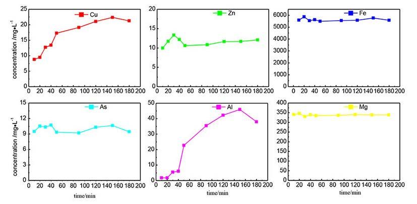
Characteristic of the precipitates
The precipitates obtained using the conditions of pH 5-6, H2O2/As = 2, reaction time 40 minutes, at room temperature and atmospheric pressure were subjected to XRD and FTIR analysis.
detrimental to the stability of the sludge. These results indicate that lower temperatures are more favourable for precipitation. Therefore, ambient temperature was chosen as the experiment condition to investigate the effect of reaction time.
Effect of reaction time on co-precipitation
In order to investigate the effect of reaction time on the coprecipitation, a series of experiments was conducted under the following conditions: H2O2/As = 2.0, reaction temperature 25°C, and pH value between 5.1 and 5.3. The results in Figure 8 show that the concentrations of Fe, As, Zn, and Mg change little with extended reaction time, which indicates that the oxidation rate of Fe(II) by hydrogen peroxide is very fast, and the reaction is completed in a very short time to form amorphous ferric arsenate (Arienzo, Chiarenzelli, and Scrudato, 2001).
However, the concentrations of Cu and Al increased with reaction time, from 8.8 mg/L and 1.77 mg/L respectively at 10 minutes to 12.7 mg/L and 5.4 mg/L at 30 minutes, 19.2 mg/L and 35.4 mg/L at 90 minutes, and reaching 22.4 mg/L and 45.9 mg/L at 150 minutes. These results indicate that Cu and Al may be adsorbed on the surface of amorphous ferric arsenate, and are re-released into the solution with increasing time.
The SEM micrographs in Figure 9 show that the particle size increases with time. At the beginning, the particles are small with rough surfaces. The particle size increases and the surface becomes smooth as reaction time increases. The results indicate that an extended reaction time improves the precipitation.

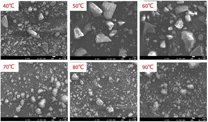
The XRD result (Figure 10) show that there are no obvious sharp peaks in the spectrum. There is just one broad band between 2θ = 20–40°, which indicates that the precipitates are amorphous. According to Berre, Gauvin, and Demopoulos (2007) this result is consistent with poorly crystalline ferric arsenate.
Figure 11 shows the FTIR spectrum of the co-precipitate in the range of 400–4000 cm-1. The band at 840 cm-1 is attributed to As–O stretching vibration of the As-O-Fe coordination (Müller et al., 2010). The band at 480 cm-1 is assigned to O-As-O bending vibration (Zhao, 1995). The bands located at 1627 cm-1 and
419 The Journal of the Southern African Institute of Mining and Metallurgy VOLUME 123 AUGUST 2023
Figure 7 SEM micographs of the precipitates obtained at different temperatures
Figure 8 Effect of reaction time on the removal of different elements from solution
Figure 9 SEM micrographs of the precipitates obtained at different reaction times
Removal of arsenic and metal ions from acidic effluents via the Fenton reaction method
3402 cm-1 exhibit strong O–H stretching and bending vibrations, respectively (Myneni et al., 1998). The band at 1127 cm-1 may be the absorption peak of γ-FeOOH (Zhao, 1995). Therefore, it can be inferred that the co-precipitates mainly exists as ferric arsenate with amorphous rather than scorodite FeAsO4·2H2O.


The SEM micrographs in Figure 12 show the granular form of the precipitates, with particle sizes up to several tens of micrometred or even larger than 100 μm. The larger size is conducive to filtration of the precipitates. The particle size analysis (Figure 13) exhibits a fairly wide range, with an average size of 81.6 μm. The large-grained structure is beneficial to the stabilization of the co-precipitates. The local amplification result in Figure 12 shows that the particles do not comprise accumulations of fine particles, but are relatively dense and uniform. This structure is also beneficial to the stability of coprecipitates.

The results of the toxicity characteristic leaching test are shown in Table II. Fe, Cu, Zn, and Mg were not detected in the leachate. Iron in the precipitates is mainly in the trivalent form, and is only sparingly soluble in the acetic acid buffer at pH 5. The Cu, Zn, and Mg contents are very low in the co-precipitates, thus it is difficult to measure their contents in acetic acid leachate. The arsenic concentration is 3.6 mg/L, which meets the requirement of China national standards of < 5 mg/L (GB5085/3-2007). The concentration of Al is 81.4 mg/L, showing that the co-precipitation does not remove aluminum effectively. According to Doerfelt et al. (2016), the aluminum ion has a stabilizing effect on the precipitates, which is inconsistent with the findings of this study. This discrepancy may be a consequence of the amorphous nature of ferric arsenate, which has a strong adsorption capacity (Müller et al., 2010). A large number of aluminum ions may be adsorbed on the surface of the co-precipitates, which will be re-dissolved into the toxicity characteristic test leachate. In addition, aluminum hydroxide is amphoteric, which may induce basic ionization in water (Equation [7]), and cause the solid Al(OH)3 to break down again.
Therefore, the leaching concentration of Al is very high in the acetic acid buffer.
Conclusions
Acidic effluent containing arsenic and metal elements was treated by the Fenton reaction under atmospheric pressure. Most of the copper, zinc, and aluminum were removed under the conditions of pH 5–6, H2O2/As = 2 at ambient temperature. However, the removal of magnesium was negligible.
Increasing the pH and H2O2 dosage increased the removal of arsenic. However, increasing the temperature will decrease arsenic removal. In addition, a lower pH, lower temperature, and increased H2O2 dosage are beneficial to the growth of large particles.
The co-precipitates were mainly composed of amorphous ferric arsenate with an average particle size of 81.6 μm. The arsenic in the residue was stable, and its concentration in the leachate from the toxicity characteristic leaching test was only 3.6 mg/L. However, the aluminum in the co-precipitates is easily re-dissolved.
Acknowledgements
This work was financially supported by the National Key Research and Development Program (No. 2019YFC1904204 and No. 2019YFC1908405)
Data availability
All relevant data is included in the paper.
References
Ahmad, A., Rutten, S., Eikelboom, M., Waal, L., Bruning, H., Bhattacharya, P., and Wal, A. 2020. Impact of phosphate, silicate and natural organic matter on the size of Fe(III) precipitates and arsenate co-precipitation efficiency in calcium containing water. Separation and Purification Technology, vol. 235. pp. 116–117.
Ahoranta, S.H., Kokko, M.E., Papirio, S., Özkaya, B., and Puhakk J.A. 2016. Arsenic removal from acidic solutions with biogenic ferric precipitates. Journal of Hazardous Materials, vol. 306. pp. 124–132.
420 AUGUST 2023 VOLUME 123 The Journal of the Southern African Institute of Mining and Metallurgy
[7]
Figure 10 XRD spectrum of the co-precipitate
Figure 11 FTIR spectrum of the co-precipitate
Figure 12 SEM micrographs of the co-precipitates
Figure 13 Particle sizes distribution of the co-precipitates
Table II
Fe As Cu Zn Mg Al – 3.56 – – – 81.4
Results of toxicity characteristic leaching test of the coprecipitates (mg/L)
Removal of arsenic and metal ions from acidic effluents via the Fenton reaction method
Arienzo, M., Chiarenzelli, J., and Scrudato, R. 2001. Remediation of metal-contaminated aqueous systems by electrochemical peroxidation: an experimental investigation. Journal of Hazardous Materials, vol. B87, no. 1–3. pp. 187–198.
Berre, J.F.L., Gauvin, R., and Demopoulos G.P. 2007. Characterization of poorlycrystalline ferric arsenate precipitated from equimolar Fe(III)–As(V) solutions in the pH range 2 to 8. Metallurgical and Materials Transactions, vol. 38B. pp. 751–762.
Bissen, M. and Frimmel, F.H. 2003. Arsenic—a review. Part II: Oxidation of arsenic and its removal in water treatment. Acta Hydrochimica et Hydrobiologica, vol. 31, no. 2. pp. 97–107.
Chen, N., Jiang, D.T., Cutler, J., Kotzer, T., Jia, Y., Demopoulos, G.P., and Rowson, J.W. 2009 Structural characterization of poorly-crystalline scorodite, iron(III)-arsenate coprecipitates and uranium mill neutralized raffinate solids using X-ray absorption fine structure spectroscopy. Geochimica et Cosmochimica Acta, vol. 73, no. 11. pp. 3260–3276.
Davis, M.A., Signes-Pastor, A.J., Argos, M., Slaughter, F., Pendergrast, C., Punshon, T., Gossai, A., Ahsan, H., and Karagas, M.R. 2017. Assessment of human dietary exposure to arsenic through rice. Science of the Total Environment, vol. 586. pp. 1237–1244.
Doerfelt, C., Feldmann, T., Roy, R., and Demopoulos, G.P. 2016. Stability of arsenate-bearing Fe(III)/Al(III) co-precipitates in the presence of sulfide as reducing agent under anoxic conditions. Chemosphere, vol. 151. pp. 318–323.
Essilfie-Dughan, J., Hendry, M.J., Warner, J., and Kotzer, T. 2013. Arsenic and iron speciation in uranium mine tailings using X-ray absorption spectroscopy. Applied Geochemistry, vol. 28. pp. 11–18.
Fujita, T., Taguchi, R., Abumiya, M., Matsumoto, M., Shibata, E., and Nakamura T. 2009. Effect of pH on atmospheric scorodite synthesis by oxidation of ferrous ions: Physical properties and stability of the scorodite. Hydrometallurgy, vol. 96. pp. 189–198.
Guan, X., Dong, H., Ma, J., and Jiang, L. 2009. Removal of arsenic from water: Effects of competing anions on As(III) removal in KMnO4–Fe(II) process. Water Research, vol. 43, no. 15. pp. 3891–3899.
Hering, J.G., Chen, P.Y., Wilkie, J.A., Elimelech, M., and Liang, S. 1996. Arsenic removal by ferric chloride. JournalAWWA, vol. 88, no. 4. pp. 155–167.
Hug, S.J. and Leupin, O. 2003. Iron-catalyzed oxidation of arsenic(III) by oxygen and by hydrogen peroxide: pH-dependent formation of oxidants in the Fenton reaction. Environmental Science and Technology, vol. 37, no. 12. pp. 2734–2742.
Jain, A., Raven, K., and Loeppert, R.H. 1999. Arsenite and arsenate adsorption on ferrihydrite: Surface charge reduction and net OH- release stoichiometry. Environmental Science and Technology, vol. 33, no. 8. pp. 1179–1184.
Jia, Y., Xu, L., Wang, X. and Demopoulos, G.P. 2007 Infrared spectroscopic and X-ray diffraction characterization of the nature of adsorbed arsenate on ferrihydrite. Geochimica et Cosmochimica Acta, vol. 71. pp. 1643–1654.
Jia, Y., Zhang, D., Pan, R., Xu, L., and Demopoulos, G.P. 2012 A novel twostep coprecipitation process using Fe(III) and Al(III) for the removal and immobilization of arsenate from acidic aqueous solution. Water Research, vol. 46. pp. 500–508.
Khuntia, S., Majumder, S.K., and Ghosh, P. 2014. Oxidation of As(III) to As(V) using ozone microbubbles. Chemosphere, vol. 97. pp. 120–124.
Korte, N.E. and Fernando, Q. 1991. A review of arsenic(III) in groundwater. Critical Reviews in Environmental Control, vol. 21. pp. 1–39.
Leupin, O.X. and Hug, S.J. 2005. Oxidation and removal of arsenic(III) from aerated groundwater by filtration through sand and zero-valent iron. Water Research, vol. 39. pp. 1729–1740.
Mandal, B.K. and Suzuki, K.T. 2002. Arsenic round the world: A review. Talanta, vol. 58. pp. 201–235.
Mihajlovic I., Strbac N., Nikolic D., and Zivkovic Z. 2011. Potential metallurgical treatment of copper concentrates with high arsenic contents.
Journal of the Southern African Institute of Mining and Metallurgy, vol. 111. pp. 409–416.
Min, X., Liao, Y., Chai, L., Yang, Z., Xiong, S., Liu, L., and Li, Q. 2015. Removal and stabilization of arsenic from anode slime by forming crystal scorodite. Transactions of Nonferrous Metals Society of China, vol. 25. pp. 1298–1306.
Molnár, L.U., Virčíkova, E., and Lech, P. 1994. Experimental study of As (III) oxidation by hydrogen peroxide. Hydrometallurgy, vol. 35, no. 1. pp. 1–9.
Müller, K., Ciminelli, V.S., Dantas, M.S., and Willscher, S. 2010. A comparative study of As (III) and As (V) in aqueous solutions and adsorbed on iron oxy-hydroxides by spectroscopy. Water Research, vol. 44. pp. 5660–5672.
Myneni, S.C.B., Traina, S.J., Waychunas, G.A., and Logan, T.J. 1998. Experimental and theoretical vibrational spectroscopic evaluation of arsenate coordination in aqueous solutions, solids, and at mineral-water interfaces. Geochimica et Cosmochimica Acta, vol. 62, no. 19/20. pp. 3285–3300.
Neupane, G., Donahoe, R.J., and Arai, Y. 2014. Kinetics of competitive adsorption/desorption of arsenate and phosphate at the ferrihydrite–water interface. Chemical Geology, vol. 368. pp. 31–38.
Otgon, N., Zhang, G., Zhang, K., and Yang, C. 2019. Removal and fixation of arsenic by forming a complex precipitate containing scorodite and ferrihydrite. Hydrometallurgy, vol. 186. pp. 58–65.
Qiao, J, Jiang, Z., Sun, B., Sun, Y., Wang, Q., and Guan, X. 2012. Arsenate and arsenite removal by FeCl3: Effects of pH, As/Fe ratio, initial As concentration and co-existing solutes. Separation and Purification Technology, vol. 92. pp. 106–114.
Pawar, V. and Gawande, S. 2015. An overview of the Fenton Process for industrial wastewater. IOSR Journal of Mechanical and Civil Engineering, vol. 2. pp. 127–136.
Rout, K., Mohapatra, M., and Anand, S. 2012. 2-Line ferrihydrite: synthesis, characterization and its adsorption behavior for removal of Pb(II), Cd(II), Cu(II) and Zn(II) from aqueous solutions. Dalton Transactions, vol. 41. pp. 3302–3312.
Singh, R., Singh, S., Parihar, P., Singh, V.P., and Prasad, S.M. 2015. Arsenic contamination, consequences and remediation techniques: A review. Ecotoxicology and Environmental Safety, vol. 112. pp. 247–270.
Styblo, M., Razo, L.M., Vega, L., Germolec, D.R., LeCluyse, E.L., Hamilton, G.A., Reed, W., Wang, C., Cullen, W.R., and Thomas, D.J. 2000. Comparative toxicity of trivalent and pentavalent inorganic and methylated arsenicals in rat and human cells. Archives of Toxicology, vol. 74. pp. 289–299.
Tang, Y., Wang, J., and Gao, N. 2010. Characteristics and model studies for fluoride and arsenic adsorption on goethite. Journal of Environmental Sciences, vol. 22, no. 11. pp. 1689–1694.
Türk, T., Alp, İ., Sezer, R., and Arslan, C. 2020. Removal of arsenic from water using copper slag. Journal of the Southern African Institute of Mining and Metallurgy, vol. 120. pp. 313–318.
Wang, Y., Lv, C., Xiao, L., Fu, G., Liu, Y., Ye, S., and Chen, Y. 2019. Arsenic removal from alkaline leaching solution using Fe (III) precipitation. Environmental Technology, vol. 40, no. 13. pp. 1714–1720.
Wang, Y., Xiao, L., Liu, H., Qian, P., Ye, S., and Chen, Y. 2018 Acid leaching pretreatment on two-stage roasting pyrite cinder for gold extraction and coprecipitation of arsenic with iron. Hydrometallurgy, vol. 179. pp. 192–197.
Wei, G., Qu, J., Zheng, Y., Qi, T., Guo, Q., Han, B., and Zhao, H. 2014 Crystallization behaviors of bayerite from sodium chromate alkali solutions. Transactions of Nonferrous Metals Society of China, vol. 24. pp. 3356–3365.
Wickramasinghe, S.R., Han, B.B., Zimbron, Z., Shen, Z., and Karim, M.N. 2004. Arsenic removal by coagulation and filtration: Comparison of groundwaters from the United States and Bangladesh. Desalination, vol. 169, no. 3. pp. 231–244.
Zhu, Y., Zhang, X., Xie, Q., Wang, D., and Cheng, G. 2006. Solubility and stability of calcium arsenates at 25°C. Water, Air, and Soil Pollution, vol. 169, no. 1–4. pp. 221–238.
Zhao, Z. 1995. Mechanism of arsenic removal in oxidized Fe-As system. China Environmental Science, vol. 15., pp. 18–21 [in Chines u
421 The Journal of the Southern African Institute of Mining and Metallurgy VOLUME 123 AUGUST 2023
HYDROMETALLURGY CONFERENCE 2024
Hydrometallurgy for the Future


The world’s dependency on metals has become more evident with the growing demand for metals required to drive advancements in the technological and digital landscape and, the energy transition for a carbon neutral future. This growing demand however, implies that the metal extraction industry will need to play a significant role in providing the world with vast quantities of metals crucial in the building of the necessary infrastructure.
Furthermore, energy and water are two critical inputs in the hydrometallurgical process flowsheets and their increasing shortage suggests the need for the development of processes that take such challenges into consideration. A circular hydrometallurgy approach focusing on innovative research and developments around energy and resource efficient processes based on closing materials and resources loops can therefore, play an important role if the metal extraction sector is to meet the current and future global metal demands. In addition, advancements in the field of artificial intelligence can also allow for the use of innovative tools such as machine learning to better understand, predict and optimise hydrometallurgical processes in a smarter and sustainable manner.
The SAIMM Hydrometallurgy conference, 2024, will bring together internationally and locally recognized scientists and engineers from mining and metal producing companies, project design and implementation entities, equipment and reagent suppliers, research and academic institutions to discuss and share innovative technologies that can assist the global world in meeting the current and future metal demands.
422 AUGUST 2023 VOLUME 123 The Journal of the Southern African Institute of Mining and Metallurgy
Removal of arsenic and metal ions from acidic effluents via the Fenton reaction method
Camielah
of Conferencing FOR FURTHER INFORMATION, CONTACT: E-mail: camielah@saimm.co.za Tel: +27 11 530 0238 Web: www.saimm.co.za
Jardine, Head
1-3 SEPTEMBER 2024
HAZENDAL WINE ESTATE, STELLENBOSCH, WESTERN CAPE, SOUTH AFRICA
The Southern African Institute of Mining and Metallurgy in collaboration with the SAIMM Western Cape Branch is hosting the
THE SOUTHERN AFRICAN INSTITUTE OF MINING AND METALLURGY FOUNDED 1894
Mechanism and control of deformation in gob-side entry with thick and hard roof strata
by J.S. Guo1, L.Q. Ma2, and I. Ngo2
Affiliation:
1School of Civil Engineering, Xuzhou University of Technology, Xuzhou, Jiangsu Province, China.
2State Key Laboratory of Coal Resources and Safe Mining, School of Mines, China University of Mining and Technology, Xuzhou, China.
Correspondence to: J.S. Guo
Email: gjscumt@163.com
Dates:
Received: 15 Aug. 2021
Revised: 16 Sept. 2022
Accepted: 16 Aug. 2023
Published: August 2023
How to cite:
Guo, J.S. Ma, L.Q., and Ngo, I. 2023 Mechanism and control of deformation in gob-side entry with thick and hard roof strata.
Journal of the Southern African Institute of Mining and Metallurgy, vol. 123, no. 8. pp. 423–434
DOI ID: http://dx.doi.org/10.17159/24119717/1707/2023
ORCID:
J.S. Guo http://orcid.org/0000-0003-0558-6533
L.Q. Ma http://orcid.org/0000-0002-8161-034X
I. Ngo http://orcid.org/0000-0002-6029-1239
Synopsis
Deformation of gob-side entries has always been a critical concern for ensuring stability in longwall coal mines. This paper addresses the significant deformation and support challenges that arise in thick and hard roof longwall faces (THRLF) due to dynamic pressure. The study aims to elucidate the characteristics and mechanisms of deformation during the retreat of the longwall face. The research findings indicated that the primary cause of deformation was the combination of advanced abutment stress resulting from longwall face mining and the movement of the lateral roof over the chain pillar. To mitigate this issue, we propose a deformation control method known as cutting off the lateral roof (COLR) over the chain pillar. Simulation results demonstrate a significant reduction in roof stress and deformation of the gob-side entry after implementing the lateral roof-cutting technique. These findings provide valuable guidance for effectively managing deformation in gob-side entries, particularly when dealing with thick and hard roof strata.
Keywords
thick and hard roof longwall face (THRLF), gob-side entry deformation, roof structure; control method, cutting off the lateral roof (COLR).
Introduction
Thick and hard roof strata are strata that are characterized by great thickness, high strength, and the absence of joints or fractures. These strata accumulate a significant amount of elastic deformation energy during the post-mining of the coal seam (Coggan et al., 2012). When fractures occur in the thick and hard roof, the accumulated energy is suddenly released, resulting in substantial deformation (Guo et al., 2017). Traditionally, gob-side entries are situated within a range of 0-50 m (the width of the chain pillar) from the last mined-out panel, which is determined by the layout of the longwall face (Li et al., 2015). As a result, the gob-side entry experiences both the primary mining impact (PMI) from the last face and the secondary mining impact (SMI) induced by the active mining face (Li et al., 2017; Hua et al., 2018). This is particularly significant for entries located in thick and hard roof longwall faces (THRLF), as the stress and deformation effects are more pronounced, increasing the likelihood of dynamic failure (Islam and Shinjo, 2009; Elmo and Stead, 2010).
Iannacchione and Tadolini, 2016) have shown that the hard roof plays a significant role in inducing deformation at the gob-side entry. (Lawson et al., 2016) have further emphasized that the thickness of the roof and its distance from the coal seam are important factors contributing to the development of deformation. Building upon this, (Lou et al., 2016) highlighted that the deformation in the entry is caused by a combination of the advanced abutment stress from the longwall face and the fractures occurring in the thick and hard roof.
To control deformation in the gob-side entry, two main approaches are commonly used: passive support and active prevention (Liu et al., 2012). Passive support focuses on reducing deformation through the strengthening of support systems. (He et al., 2011) proposed a support scheme using intensive cable trusses and small-diameter anchors with high pre-stressed tension. Wang et al., (2014) suggested the use of highstrength bolts with high pre-stress tension as a support scheme. However, the passive support method was found to be ineffective and disrupted regular production of the longwall face (Wang et al., 2015). On the other hand, active prevention aims to address the main cause of deformation by adjusting the width of the coal pillar to maintain entry stability. Bai et al. (2015) and Feng et al. (2018) proposed locating the entry in a stress reduction zone, achieved by reducing the coal pillar width (the lateral stress of the surrounding rock can be divided into three zones: the stress reduction zone, stress increase zone, and original rock
423 The Journal of the Southern African Institute of Mining and Metallurgy VOLUME 123 AUGUST 2023
Mechanism and control of deformation in gob-side entry
stress zone). However, designing a small chain pillar requires careful consideration of multiple factors to prevent more serious deformations. Xu et al. (2017) prevented deformation by increasing the width of the chain pillar to isolate the mining effects of two adjacent faces. However, wider coal pillars result in coal resource wastage. In recent years, the ‘cutting off roof strata method’ has been adopted in various mines to maintain entry stability with the development of related technologies (He et al., 2017). This method involves arranging a cutting line at the edge of the gob along the strike of the entry. By blasting or hydraulic fracturing, the hanging part of the lateral roof strata is removed, eliminating its impact on the entry.
This paper analyses the deformation events of 11215 tail entry in the Xiaojihan coal mine. The mechanism of deformation of the gob-side entry in THRLF was investigated. Finally, the deformation control method was proposed to eliminate or weaken the deformation of the gob-side entry.
Geological conditions of the study area
Mining geological conditions
The coal seams in Northern Shaanxi are part of the Jurassic coalfields, which contribute approximately 7% of China’s total annual coal output. These coalfields can be further divided into Yushen and Yuheng fields. The Yushen field is characterized by shallow coal seams that range from 40-200 m in depth. Due to this relatively shallow depth, the coal seam in this area has been extensively exploited on a large scale. On the other hand, the Yuheng field consists of deeper coal seams, with depths ranging from 300-500 m.
The Xiaojihan mine, located in the Yuheng field, is the first modern mine in the area and has a production capacity of 10 Mt/a. Due to its significance, the mining experience gained from Xiaojihan is of great importance for the design and operation of subsequent mines in the region. Within Xiaojihan mine, the 11215 longwall face is situated in Panel 11. It is adjacent to the 11213 gob,
as shown in Figure 1. The chain pillar between these two faces has a width of 20 m. The 11215 face extends 4,888 m in the direction of mining and has a width of 280 m. The 11215 headentry and tail entry serves the 11215 longwall face. It should be noted that the 11215 tailentry, which is the gob-side entry, experiences disturbance due to the mining activities on both the 11213 faces (PMI) and the 11215 faces (SMI). In Figure 1, the region of SMI is highlighted by the red ellipse, with a length of 3588 m. This paper primarily focuses on analysing and understanding the deformation events that occur in the region of SMI within the 11215 tailentry.
Roof geological conditions
Taking the 11215 longwall face as an example, four geological boreholes were arranged along the advancing direction of the face (Figure 2).
he distances from the 11215 open-off cut were 00 m, 1455 m, 3000 m, and 4000 m, respectively. The roof strata of the 11215 face exhibit an alternating layered structure composed of arkose and mudstone. Notably, arkose layers with a thickness exceeding 5 m constitute 58.2% of the total thickness, indicating a predominant presence of intact arkose in the roof strata.
Characteristics of deformation in gob-side entry
Deformation of the 11215 tailentry
Before the 11215 face advanced to the 11213 gob (PMI), the deformation of the 11215 tail entry occurred mainly within the range of 0−40 m preceding the 11215 face. The maximum recorded roof subsidence was 295 mm, accompanied by a width reduction of 585 mm. After the 11215 working faces advanced to the 11213 gob (SMI), the deformation was characterized by severe convergence m of the whole section. The deformation was mainly within the range of 0−60 m preceding the 11215 face. Maximum roof subsidence and width reduction were 610 mm and 956 mm, respectively. An anchor cable in the roof and an anchor bolt in the chain pillar were broken within the range of 0−20 m preceding the 11215 face (Figure 3).
424 AUGUST 2023 VOLUME 123 The Journal of the Southern African Institute of Mining and Metallurgy
11213 longwall face 11215 longwall face No.
No.
No.
Figure 1—Schematic diagram of the coal mine and working faces. (a) Location of Xiaojihan coal mine. (b) 11213 and 11215 working face layout
13 panel
11 panel
12 panel
N 11213 gob 11215 longwall face 1300m 3588m 11213 open-off cut ZK1509 ZK15A09 ZK1309 ZK1209 11215 headentry 11215 tailentry Secondary mining impact (SMI) (a) (b)
No. 14 panel China Shaanxi
Mechanism and control of deformation in gob-side entry
Deformation events
During the advance of the 11215 face towards the 11213 gob, a series of significant failure events were observed. To analyse these events, four typical incidents were selected and are documented in Table I and illustrated in Figure 4.
Mechanism of deformation in gob-side entry
Advanced abutment stress caused by longwall face mining FLAC3D software was used to simulate and analyse the stress and deformation patterns during the mining operations of longwall working faces. FLAC3D is a renowned finite difference numerical simulation software package that incorporates diverse material models to accurately replicate the stress and deformation behaviors of elastic-plastic media, including rock and soil. It enjoys widespread adoption and recognition within the domains of rock mechanics, soil mechanics, and mining engineering.
Parameters of the model
Geometric dimensions
A model with dimensions of 640 × 200 × 114.5 m was constructed to simulate the strata movement (Figure 5). Strata 114.5 m thick were modelled and the rest of the overburden stress was exerted
on the top boundary as pressure (Jaiswal and Shrivastva, 2009; Sherizadeh and Kulatilake, 2016).
Boundary conditions
Displacement constraints were applied to the front, back, left, right, and bottom boundaries. To eliminate the disturbance effect caused by coal seam mining, the boundary of the model should exceed the boundary of the basin formed when the surface above the goaf subsides. In this modelling scenario, the rock strata movement angle was assumed to be 75° (Qian et al., 2003; Xu et al., 2017).
After calculations, it was determined that leaving 22.7 m coal pillars on both sides would ensure sufficient mining. Therefore, a boundary of 26 m and 28 m was left on both sides of the inclined direction, while a boundary of 25 m was left on both sides of the strike direction, satisfying the requirements.
Rock/coal strata properties
The Mohr-Coulomb failure criterion was used in the model. The detailed physical and mechanical parameters for each rock layer and coal seam in the model can be found in Table II, providing comprehensive information for the analysis and modeling process.
Monitoring points layout
To monitor the stress and deformation of 11215 tail entry, four


425 The Journal of the Southern African Institute of Mining and Metallurgy VOLUME 123 AUGUST 2023
ZK1309 ZK1509 ZK15A09 420m 410m 400m 390m 380m 370m 355m 345m 335m 325m 315m 305m ZK1209 #2 Coal seam Arkose Arkose Arkose Arkose Arkose Arkose Silty mudstone Silty mudstone Silty mudstone Silty mudstone Silty mudstone Silty mudstone Mudstone Mudstone Mudstone Lithology Thickness /m 4.5 19.8 6.5 5.7 9.9 3.7 10.6 10.9 10.1 7.6 4.2 2.5 5.0 6.2 3.2 4.6 1000m 2000m 3000m 4000m 0 11215 open-off cut Main roof 11215 working face -100m Immediate roof Buried depth
Figure 2—Schematic of stratigraphy in 11215 face
0 10 20 30 40 50 60 70 80 90 100 110 120 0 100 200 300 400 500 600 700 Roofsubsidence/mm Advancinglength/m PMI SMI Anchorcablebroken Diameter 21.8mm Length 5600mm Anchoringforce200kN Parameters of anchorcables 0 10 20 30 40 50 60 70 80 90 100 110 120 0 100 200 300 400 500 600 700 800 900 1000 Widthreduction/mm Advancinglength/m PMI SMI Anchorboltbroken Parameters of anchorbolt Diameter 20mm Length2300mm Anchoringforce50kN (a) (b)
Figure 3—Deformation of the 11215 tailentry. (a) Roof subsidence. (b) width reduction
Mechanism and control of deformation in gob-side entry


Table I
Deformation events in 11215 tailentry
Date Distance to 11213 open-off cut

April 12 264 m
May 11 396 m
June 4 583 m
July 21 1124 m
Field situation
Roof subsidence of 11215 tailentry was up to 1.2 m in the advanced section and the hydraulic props were bent. The junction of 11215 faces and tailentry was blocked.
The floor heaved 0.8m; the rib spalled 1.1m on the chain pillar side and 0.9 m on the panel side in the advanced section of 11215 tailentry, which stopped production at the face.
The roof subsidence was up to 1.3 m and the roof beam was broken. The rib spalled 1.5m in the chain pillar side and knocked down supporting hydraulic props.


Rib bulged 1.2 m in the sidewall of the chain pillar side. The anchor cable in the roof and the anchor bolt in the chain pillar were broken.
monitoring points were created. P1 is monitoring the variation of stress, P2 is monitoring the variation of roof subsidence, and P3 /P4 are monitoring the variation of width reduction.
Excavation steps
The excavation process of the model follows the actual mining sequence. It begins by mining the mining roadway, followed by excavation of the 11213 working face, and finally the 11215 working face. The progression of the mining process aligns with the real-time mining progress, which was typically at a rate of 10 m/d. The excavation was carried out every 10 m in accordance with this mining schedule. This approach ensures that the model accurately represents the sequential excavation process observed in practical mining operations.
Simulation results
To analyse the excavation process in detail, five stages were selected for analysis:

Stage 1: Extraction of the 11215 tailentry.
Stage 2: Mining of the 11213 face (PMI).
Stage 3: Advancement of the 11215 face to the location of the 11213 open-off cuts (SMI).
Stage 4: Advancement of the 11215 face to a location approximately 20 m away from the 11213 open-off cut (SMI).

Stage 5: Advancement of the 11215 face to a location approximately 40 m away from the 11213 open-off cut (SMI). These stages were chosen to closely examine the specific steps and events during the model excavation process. In this section ‘measured’ means ‘as calculated by the model’.
426 AUGUST 2023 VOLUME 123 The Journal of the Southern African Institute of Mining and Metallurgy
28m 25m 26m 20m 11213 gob 200m 640m 114.5m 280m
11215 longwallface P2 P3 P4 P1 11215 tailentry 11215 longwall face Chain pillar 11213 gob Silty mudstone Silty mudstone Silty mudstone Silty mudstone Silty mudstone Silty mudstone Arkose Arkose Arkose Arkose Arkose Arkose Mudstone Mudstone Mudstone #2 coal seam
11213open-offcut
Figure 5-Numerical model
Hydraulic prop bent “4.12” event Floor heaved “5.11” event Beam broken “6.4” event Coal pillar bulged “7 21” event 1.2m (a) (b) (c) (d)
Figure 4—Field situation of deformation events
Mechanism and control of deformation in gob-side entry
Table II
Rock physical and mechanical parameters
These stages were chosen to closely examine the specific steps and events during the model excavation process. In this section ‘measured’ means ‘as calculated by the model’.
After the excavation of the 11215 tail entry (Stage 1), the vertical stress measured was 5.9 MPa. This stress increased to 8.0 MPa after the mining of the 11213 faces (Stage 2, PMI). As the 11215 faces advanced to the location of the 11213 open-off cuts (Stage 3, SMI), the peak abutment stress in the advanced section of the 11215 tail entry reached 8.5 MPa. Further advancement of the 11215 face to a location approximately 20 m away from the 11213 open-off cuts (Stage 4, SMI) resulted in a peak abutment stress of 9.3 MPa in the advanced section of the 11215 tail entry. Finally, when the 11215 face advanced to a location approximately 40 m away from the 11213 open-off cuts (Stage 5, SMI), the peak abutment stress in the advanced section of the 11215 tail entry reached 9.8 MPa (as depicted in Figure 6 and summarized in Table III).
After the excavation of the 11215 tail entry (Stage 1), the roof subsidence in the advanced section was measured at 126.8 mm, and the width reduction of the two sidewalls was 44.0 mm. Upon mining the 11213 working face (Stage 2, PMI), the roof subsidence of the 11215 tail entry increased to 244.9 mm, and the width reduction of the two sidewalls increased to 143.7 mm. When the 11215 face advanced to the location of the 11213 open-off cut (Stage 3, SMI), the maximum subsidence of the roof and the width reduction of the two sidewalls in the advanced section reached 265.7 mm and 181.7 mm, respectively. Further advancement of the 11215 face to a location approximately 20m away from the 11213 open-off cut (Stage 4, SMI) resulted in a maximum roof subsidence of 318.5 mm and a width reduction of the two sidewalls of 235.1 mm. Finally, as the 11215 face advanced to a location approximately 40 m away from the 11213 open-off cut (Stage 5, SMI), the maximum roof subsidence in the advanced section of the 11215 tail entry reached 360.3 mm, with a width reduction of the two sidewalls of 286.7 mm (as depicted in Figure 7 and summarized in Table III).
Stress and deformation data of 11215 tailentry
stages
Ultimately, it is important to note that the roof stress and deformation experienced by the simulated 11215 tail entry during the SMI phase were markedly greater compared to the PMI phase
427 The Journal of the Southern African Institute of Mining and Metallurgy VOLUME 123 AUGUST 2023
Number Strata Thickness (m) Density (kg/m3) Bulk modulus (GPa) Shear modulus (GPa) Cohesion (MPa) Friction angle (°) Tensile strength (MPa) 1 Silty mudstone 7.6 2566 1.4 0.4 5.4 32.9 1.6 2 Arkose 10.1 2630 5.0 2.4 13.5 30.2 4.3 3 Mudstone 10.9 2550 1.3 0.3 5.1 28.0 1.2 4 Arkose 10.6 2630 5.0 2.4 13.5 30.2 4.3 5 Mudstone 3.7 2550 1.3 0.3 5.1 28.0 1..2 6 Arkose 9.9 2630 5.0 2.4 13.5 30.2 4.3 7 Silty mudstone 5.7 2566 1.4 0.4 5.4 32.9 1.6 8 Arkose 19.8 2630 5.0 2.4 13.5 30.2 4.3 9 Silty mudstone 6.5 2566 1.4 0.4 5.4 32.9 1.6 10 #2 Coal seam 4.5 1467 0.5 0.3 2.1 24.0 1.9 11 Silty mudstone 4.2 2566 1.4 0.42 5.4 32.9 1.6 12 Mudstone 2.5 2550 1.3 0.3 5.1 28.0 1.2 13 Silty mudstone 5.0 2566 1.4 0.4 5.4 32.9 1.6 14 Arkose 6.2 2630 5.0 2.4 13.5 30.2 4.3 15 Silty mudstone 3.2 2566 1.4 0.4 5.4 32.9 1.6 16 Arkose 4.6 2630 5.0 2.4 13.5 30.2 4.3 0102030405060708090100 5 6 7 8 9 10 Initial stress PMI SMI Advancing direction 40m Advancing length/m Stage 1 Stage 2 Stage 3 Stage 4 Stage 5 20m 11213 open-off cut Vertical stress/MPa
Figure 6—Variation of roof stress at different mining stages
Table III
Stage Peak abutment stress (MPa) Deformation Roof subsidence (mm) Width reduction (mm) 1 5.9 126.8 44.0 2 8.0 244.9 143.7 3 8.5 265.7 181.7 4 9.3 318.5 235.1 5 9.8 360.3 286.7
at different mining
Mechanism and control of deformation in gob-side entry
As a result, it becomes evident that the intensified abutment stress resulting from the mining of the 11215 longwall face stands as a significant contributing factor to the deformation observed in the gob-side entry. This highlights the profound impact of longwall face mining on the stability and structural integrity of underground mining systems.
Movement of the lateral roof over chain pillar
Relationship between lateral roof and entry’s stability
Roof strata were subjected to bending subsidence along the inclined direction of the longwall face, resulting in Blocks A, B, and C that were hinged to each other. Investigations indicated that the deformations of gob-side entry under three different spatial positions of the main roof fracture line were different (Zha et al., 2014; Yin et al., 2016; Xu et al., 2017). The position of the main roof fracture line can be categorized as follows:
➤ The fracture line was located on the side of the unmined coal (Figure 8a)
➤ The fracture line was directly above the gob-side entry (Figure 8b)
➤ The fracture line was located above the chain pillar (Figure 8c).
Numerical simulations and on-site data have provided evidence that when the fracture line was situated on the side of the unmined solid coal, it resulted in the greatest length of the suspended roof. This, in turn, leads to the highest bending moment, as well as the
most severe stress and deformation in the rock surrounding the entry. On the contrary, when the fracture line is positioned above the coal pillar, it results in the shortest length of the suspended roof, the lowest bending moment, and the most stable surrounding rock in the entry.
Mechanical model of lateral roof
As mentioned above, the stability of 11215 tail entry was mainly dependent on the structure of the lateral main roof over the chain pillar. Therefore, the structure of the cantilever beam was established (Figure 9).
The main roof stratum can be considered as a semi-infinite beam, subjected to vertical force P and axial force N, as described in previous studies (Qian et al., 2003; Pan and Gu, 2015). Based on the principles of Timoshenko beam theory, the deflection curve equation for the main roof can be expressed as follows:
where P + -ky
where: E is the elastic modulus of roof strata; y is the vertical displacement of the main roof; k is Winkler bed coefficient.
According to boundary conditions, the deflection curve equation can be obtained as follows [Qian et al., 2003]:


428 AUGUST 2023 VOLUME 123 The Journal of the Southern African Institute of Mining and Metallurgy
[1]
[2] Herein:
0102030405060708090100 100 150 200 250 300 350 400 Initial roof subsidence PMI 40m Advancing distance/m Stage 1 Stage 2 Stage 3 Stage 4 Stage 5 Roof subsidence/mm 20m 11213 open-off cut Advancing direction SMI 0102030405060708090100 0 50 100 150 200 250 300 Initial width reduction PMI Coal pillar rib contraction SMI 40m Advancing length/m Stage 1 Stage 2 Stage 3 Stage 4 Stage 5 Width reduction/mm 20m 11213 open-off cut Advancing direction (a) (b)
Figure 7—Deformation of 11215 tailentry at different mining stages (a) Roof subsidence, (b) width reduction
Unmined coal Chain pillar Gob Block A Block B Block C Fracture line Gob-side entry Chain pillar Gob Block A Block B Block C Fracture line Unmined coal Gob-side entry Gob-side entry Chain pillar Gob Block A Block B Block C Fracture line Unmined coal (a) (b) (c)
Figure 8—Structure of lateral main roof. (a) Fracture line on the unmined coal side, (b) fracture line above the entry, (c) fracture line on the chain pillar side
Mechanism and control of deformation in gob-side entry
where: h is the main roof thickness (19.8 m); E is the elastic modulus of the main roof (7.36 GPa); I is the section moment of the main roof (I=bh3/12, where b=1); ΔS is the vertical displacement of Block B (ΔS=h/6); LB is the length of Block B; L´ is the length of the hanging part of Block B (11.7 m in this case, more details in the next section); Q is the shear force between fractured rock blocks (Q´=LB(γh+q)); γ is the bulk density of main roof (23 kN/m3 in this case); q is the loads on strata above the main roof (9.25×10³ kN/m in this case); N is the axial force (N=LB Q´/2(h-ΔS)); k is the bed coefficient of coal and immediate roof , immediate roof thickness coal seam thickness h1 = 4.5 m, E1 = 1.06 GPa, h2=6.5 m, E2=1.67 GPa, k = 1.23×10³ kN/ m.
Hanging length of Block B
To determine the actual length of the hanging part of Block B, a hydraulic drilling technique was employed. By monitoring the leakage of flushing fluids in the drill-holes, the development of fracture zones in the overburden strata could be determined. The drill site was situated at a distance of 520 m from the 11213 open-off cut. The drill holes were arranged in a fan pattern. The layout and parameters of the drill-holes can be seen in Figure 10 and Table IV.
The detection results suggested that starting points of complete leakage of flushing fluids in 30°, 35° and 40° drill holes were D, E, and F, respectively. The horizontal distances from D, E, and F to the boundary of the chain pillar, namely the length of the roof hanging part (L´), were 9.4 m, 11.6 m, and 14.1 m respectively. The average value was 11.7 m.
Fracture line location of the main roof
The bending moment at the cross section of the cantilever beam can be calculated by (Wang et al., 2014; Xu et al., 2017):
Table IV
Parameters of drill holes
Substituting the parameters of 11215 face into Equation (3), the bending moment of the cantilever beam could be obtained (Figure 11). The maximum value of the bending moment was calculated at x = 30 m and the fracture line of the main roof was located at 30 m outside the chain pillar.


In conclusion, the core reason for deformation in 11215 tailentry was the superimposition effect of the advanced abutment
stress caused by 11215 face mining and the bending of the lateral roof over the chain pillar.
Control method of deformation in gob-side entry
Due to the inevitable advancement abutment stress generated by mining activities, the feasible approach is to regulate the lateral movement of the main roof. As a result, the ‘cutting off the lateral roof’ (COLR) method was implemented to manage the fracture line in the roof situated at the chain pillar side, as illustrated in Figure 12. The effectiveness of COLR primarily hinges upon optimizing
429 The Journal of the Southern African Institute of Mining and Metallurgy VOLUME 123 AUGUST 2023
Figure 9—Mechanical model of lateral roof strata. (a) Structure of cantilever beam, (b) distribution of forces
Figure 10—Measured lengths of hanging part of the lateral roof
Hole Inclined angle (°) Horizontal angle (°) Depth (m) Diameter (mm) Distance between holes (m) #1 30 0 45 93 #2 35 0 50 93 1 #3 40 0 60 93 100 80 60 40 20 0 0 50 100 150 200 250 300 350 400 450 500 4.5m 5.5m 20m 11215longwallface 11215tailentry Chainpillar 30m M /MN·m x/m Fractureline
Figure 11—Distribution of bending moment in the cantilever beam
[3]
Block A Block B Block C 11213 gob Chain pillar 11215 tailentry 20m 5.5m Main roof Block A O x Block B q M 0 N' LB Q' N h L' y Q0 Centerline of 11215 tailentry ΔS 22.75m h2 h1 k1 k 2 (a) (b) Block A Block B Block C #1 #2 #3 D E F 9.4m 11.6m 14.1m 30° 35° 40° 11213 gob 11215 longwall face Chain pillar 11215 tailentry (b)
Mechanism and control of deformation in gob-side entry
equal to the thickness of the immediate roof), 15 m, and 25 m (approximately equal to the combined thickness of the immediate roof and main roof).

Variation of the roof stress
As the cutting height increased, the stress release zone above the 11215 tailentry expanded accordingly. This can be observed in Figure 13, where the scope of the stress release zone becomes larger with the increase in cutting height.
the cutting height and cutting angle parameters. To achieve this, numerical simulations were conducted to refine and optimize these parameters, ensuring enhanced outcomes for the COLR technique.


Simulation scheme


This section of the simulation builds upon the numerical model discussed in Section 4. To simulate the cutting line, separate unit groups are set in the model, as illustrated in Figure 12. The primary focus of this study is to examine the impact of two factors: the height of the cutting seam (0 m, 5 m, 15 m, 25 m) and the angle (0°, 15°, 30°, 45°) on the stress and deformation of the surrounding rock in the 11215 tailentry.

Cutting height
The determination of the cutting height primarily depends on practical geological conditions, as indicated in previous studies (Poulsen, 2010; Jawed and Sinha, 2018). In the case of the 11215 tailentry, the immediate roof had a thickness of 6.5 m, while the main roof had a thickness of 19.8 m. Therefore, simulations were conducted to assess the variations in roof stress and deformation in the 11215 tailentry for different cutting heights: 5 m (approximately
Analysis of the roof stress in the 11215 tail entry revealed the following results: When the roof was uncut, the average roof stress was 8.1 MPa. With a cutting height of 5 m, the average roof stress decreased to 7.0 MPa, representing a reduction of 15%. When the cutting height was increased to 15 m, the average roof stress further decreased to 6.2 MPa, showing a reduction of 24%. With a cutting height of 25 m, the average roof stress dropped significantly to 4.4 MPa, indicating a reduction of 45.7%. These findings are visually represented in Figure 14 and summarized in Table V.
430 AUGUST 2023 VOLUME 123 The Journal of the Southern African Institute of Mining and Metallurgy 0102030405060708090100 0 1 2 3 4 5 6 7 8 9 10 45.7% 24% 15% Advancing length/m Uncut Cutting height=5m Cutting height=15m Cutting height=25m Vertical stress/MPa 11213
Advancing direction
open-off cut
Figure 14—Variation of roof stress with different cutting heights
11213 gob Cutting angle Cutting height 11215 longwall face 11215 tailentry Chain pillar 11213 gob Cutting line
11215longwallface
Figure 12—Schematic of COLR method
SZZ/MPa 11213 gob Chain pillar 11215 tailentry SZZ/MPa Stress release zone 5m (a) (b) SZZ/MPa 15m Stress release zone (c)
Figure 13—Contours of roof stress with different cutting heights. (a) Uncut, (b) cutting height 5m, (c) cutting height 15m, (d) cutting height 25m
Mechanism and control of deformation in gob-side entry
Table V
Stress and deformation data of 11215 tailentry with different cutting heights
Variation of the roof stress
With the increase of cutting angle, the scope of the stress release zone in the surrounding rock above the 11215 tail entry increased (Figure 16).
When the roof remained uncut in the 11215 tail entry, the average roof stress measured at 8.1 MPa. However, with different cutting angles, significant reductions in roof stress were observed. For a cutting angle of 0°, the average roof stress decreased to 4.4 MPa, representing a reduction of 45.7%. Similarly, at a cutting angle of 15°, the average roof stress reached 4.4 MPa, resulting in a decrease of 46.2%. When the cutting angle was set at 30°, the average roof stress measured 4.5 MPa, reflecting a decrease of 45%. Lastly, with a cutting angle of 45°, the average roof stress was recorded at 4.5 MPa, showing a decrease of 45.1%. (refer to Figure 17 and Table VI).
Variation of the deformation
Figure 15 illustrates the variations in roof subsidence resulting from different cutting heights employed in the 11215 tail entry.
Without any cutting, the average roof subsidence in the 11215 tail entry was 251.7 mm. When the cutting height was set at 5 m, the average roof subsidence decreased to 234.9 mm, representing a reduction of 6.7%. With a cutting height of 15 m, the average roof subsidence further decreased to 228.0 mm, showing a reduction of 9.4%. By increasing the cutting height to 25 m, the average roof subsidence dropped to 223.5 mm, resulting in a reduction of 11.2%.
Additionally, the average width reduction also decreased as the cutting height increased. Specifically, the average width reduction decreased by 3.3%, 7.3%, and 13.5% when the cutting height increased from 5 m to 15 m and finally 25 m. These results are visualized in Figure 15a (roof subsidence) and Figure 15b (width reduction) and summarized in Table V.
In conclusion, the results of COLR were best when the cutting height was 25 m, that is when the cutting height can ensure cut off of the main roof.
Cutting angle
For the convenience of construction, the cutting angle was usually taken as an integer multiple of 5°. Therefore, the variation of the roof stress and the deformation of 11215 tailentry were simulated for cutting angles if 0°, 15°, 30°, and 45°.
It is obvious that the cutting angle had only a minor effect on the roof stress. But the scope of the stress release zone became larger as the cutting angle increased.
Variation of the deformation
When the roof was left uncut, the 11215 tailentry exhibited an average subsidence of 251.7 mm. However, when the cutting angle was set to 0°, the average roof subsidence decreased to 223.5 mm, resulting in an 11.2% reduction. Interestingly, as the cutting angle increased beyond this range, namely to 15°, 30°, and 45°, the average roof subsidence showed consecutive increases of 2.6%, 13%, and 23.6% respectively (Figure 18a).
Similarly, when the cutting angle was set to 0°, the average roof subsidence of the 11215 tailentry decreased by 13.5%. However, as the cutting angle increased from 15° to 30° and 45°, the roof subsidence showed consecutive increases of 5.3%, 27.4%, and 44.2% respectively (refer to Figure 18b and Table VI). This can be attributed to the fact that as the cutting angle increased, the length of the hanging lateral roof above the 11215 tailentry also increased. Consequently, the deformation of the surrounding rock of the 11215 tailentry became more severe, leading to increased roof subsidence..
Based on the simulation results, it is observed that the deformation of the 11215 tailentry decreased when the cutting angle was set to 0° and slightly increased when the cutting angle was 15°. Considering both the roof release results and the deformation of the 11215 tailentry, it is recommended to maintain a cutting angle within the range of 0° to 15°.
431 The Journal of the Southern African Institute of Mining and Metallurgy VOLUME 123 AUGUST 2023
Cutting height (m) Peak abutment stress (MPa) Deformation Roof subsidence (mm) Width reduction Uncut 8.1 251.7 138.1 5 7.0 234.9 133.5 15 6.2 228.0 128.0 25 4.4 223.5 119.4
Figure
0102030405060708090100 0 25 50 75 100 125 150 175 200 10 20 30 115 120 125 130 135 140 145 150 155 Uncut Cutting height=5m Cutting height=15m Cutting height=25m Advancing length/m Width reduction/mm 11213 open-off cut Advancing direction 13.5% 7.3% 3.3% 0102030405060708090100 200 210 220 230 240 250 260 270 280 290 300 11.2% 9.4% 6.7% Uncut Cutting height=5m Cutting height=15m Cutting height=25m Advancing distance/m Roof subsidence/mm 11213 open-off cut Advancing direction (a) (b)
15—Variation of deformation with different cutting height. (a) Roof subsidence, (b) width reduction
Mechanism and control of deformation in gob-side entry
VI
Stress and deformation data of 11215 tailentry with different cutting angles


Discussion
➤ The COLR method involves two primary techniques: borehole blasting and hydraulic fracturing (Huang et al., 2017). The
borehole blasting technique generally yields superior stress release results, although it carries a relatively higher hazard level. Mishandling of this technique can lead to significant accidents (Liu et al., 2017). On the other hand, the hydraulic fracturing technique is considered safe and easily manageable. However, it may not be as effective as borehole blasting in achieving stress release for certain thick and hard rock formations.
➤ The simulation results demonstrate that the COLR method yields optimal outcomes with a cutting angle of 0°. However, in practical situations, an excessively small cutting angle can lead to roof crushing and pose challenges for support. Hence, it is crucial to consider the geological strata and support conditions when determining the appropriate cutting angle.
➤ The advancing rate of the longwall face is also an important factor affecting the deformation of the gob-side entry. Statistical results show that deformation events in 11215 tail entry occurred when the advancing speed of 11215 face exceeded 10 m/d. For instance, 5 days prior to the ‘4.12’ event, the average advancing speed of the working face was recorded
432 AUGUST 2023 VOLUME 123 The Journal of the Southern African Institute of Mining and Metallurgy Table
Cutting angles (°) Peak abutment stress (MPa) Deformation Roof subsidence (mm) Width reduction Uncut 8.1 251.7 138.1 0 4.4 223.5 119.4 15 4.4 258.3 145.9 30 4.5 284.3 175.9 45 4.5 311.1 199.1
0102030405060708090100 0 1 2 3 4 5 6 7 8 9 10 45%-46.2% Advancing length/m Uncut Cutting angle=0° Cutting angle=15° Cutting angle=30° Cutting angle=45° Vertical stress/MPa 11213 open-off cut Advancing direction
Figure 17—Variation of roof stress with different cutting angle
SZZ/MPa 25m Stress release zone SZZ/MPa 15° Stress release zone SZZ/MPa 30° Stress release zone 45° Stress release zone SZZ/MPa (a) (b) (c) (d)
Figure 16—Contour of roof stress with different cutting angles. (a) Cutting angle 0°, (b) cutting 15°, (c) cutting 30°, (d) cutting height 45°
Mechanism and control of deformation in gob-side entry
as 11.5 m/d, peaking at 14.4 m/d. Similarly, 5 days leading up to the ‘5.11’ event, the average advancing speed averaged at 10.1m/d, with a maximum speed of 12.7 m/d. Three days prior to the ‘6.4’ event, the average advancing speed measured 12.0 m/d, with a peak speed of 13.35m/d. Finally, 4 days before the ‘7.21’ event, the average advancing speed was documented at 12.0 m/d, reaching a maximum of 14.7 m/d. Therefore, it can be considered that reducing the advancing speed of the longwall face will reduce the possibility of deformation occurring in the gob-side entry.
Conclusions
➤ The roof stress and deformation of the gob-side entry were analysed through field observations and numerical simulations, revealing notable variations. The findings highlighted that the impact of secondary mining resulted in greater roof stress and deformation compared to that of primary mining.
➤ The mechanism behind deformation in the gob-side entry of a thick and hard roof longwall face was analysed. The primary factor was identified as the combined effect of advanced abutment stress resulting from longwall face mining and the lateral movement of the roof over the chain pillar. To further understand this phenomenon, mechanical structure models employing a cantilever beam approach were developed. Through calculations, it was determined that the fracture line of the roof was located approximately 30 m outside the chain pillar.
➤ A deformation control method for cutting off the lateral roof was proposed. The effectiveness of this method was evaluated by simulating stress release results under various cutting heights and cutting angles. The simulation revealed that the optimal outcome was achieved when the cutting height ensured the complete cut-off of the main roof, combined with a cutting angle ranging from 0° to 15°. This finding suggests that careful consideration of both cutting height and angle is essential for successful lateral roof deformation control.
Acknowledgements
This work was supported by The Natural Science Foundation of the Jiangsu Higher Education Institutions of China (23KJD440002) and Jiangsu Province Industry University Research Cooperation Project (BY20221261).
Author Contributions
Jinshuai Guo carried out the study and wrote the manuscript; Liqiang Ma supervised the study; Ichhuy Ngo proof read the manuscript.
Conflicts of Interest
The authors declare no conflict of interest.
References
Bai, J.B., Shen, W.L., Guo, G.L., Wang, X.Y., and Yu, Y. 2015. Roof deformation, failure characteristics, and preventive techniques of gob-side entry driving heading adjacent to the advancing working face. Rock Mechanics and Rock Engineering, vol. 48, no. 6. pp. 2447–2458.
Chen, S.Y., Song, C.S., Guo, Z.B., and Wang, Y. 2016. Asymmetric deformation mechanical mechanism and control countermeasure for deep roadway affected by mining. Journal of China Coal Society, vol. 41, no. 4. pp. 246–254.
Coggan, J., Gao, F.Q., Stead, D., and Elmo, D. 2012. Numerical modelling of the effects of weak immediate roof lithology on coal mine roadway stability. International Journal of Coal Geology. vol. 90, no. 1. pp. 100–109.
Elmo, D. and Stead, D. 2010. An integrated numerical modelling–discrete fracture network approach applied to the characterisation of rock mass strength of naturally fractured pillars. Rock Mechanics and Rock Engineering. vol. 43, no. 1. pp. 3–19.
Feng, G.R., Wang, P.F., Chugh, Y.P., Zhao, J.L., Wang, Z.Q., and Zhang, Z.P. 2018. A coal burst mitigation strategy for tailgate during deep mining of inclined longwall top coal caving panels at huafeng coal mine. Shock and Vibration vol. 5929785.
Guo, J.S., Ma, L.Q., Wang, Y., and Wang, F.T. 2017. Hanging wall pressure relief mechanism of horizontal section top-coal caving face and its application—a case study of the urumqi coalfield, China. Energies, vol. 10, no. 9. p. 1371.
He, F.L., Yin, D.P., Yan, H., Li, Q., and Yang, H.Z. 2011. Experiment of powerful anchor truss support system applied to mining roof falling gateway. Coal Science & Technology, vol. 39, no. 2. pp. 1–5.
He, M.C., Li, C., Gong, W.L., Sousa, L.R., and Li, S.L. 2017. Dynamic tests for a constant-resistance-large-deformation bolt using a modified SHTB system. Tunnelling and Underground Space Technology. vol. 64, no. 4. pp. 103–116.
Hua, X.Z., Ming, Y., Liu, Q.J., and Yang, P. 2018. Model test on evolution mechanism of floor heave in gob-side retaining entry of deep mine. Journal of Mining and Safety Engineering. vol. 35, no. 1. pp. 1–9.
433 The Journal of the Southern African Institute of Mining and Metallurgy VOLUME 123 AUGUST 2023
0102030405060708090100 200 225 250 275 300 325 350 375 400 23.6% 13% 2.6% 11.2% Uncut Cutting angle=0° Cutting angle=15° Cutting angle=30° Cutting angle=45° Advancing distance/m Roof subsidence/mm 11213 open-off cut Advancing direction 0102030405060708090100 50 100 150 200 250 300 350 20 30 140 145 150 155 160 44.2% 27.4% 13.5% Uncut Cutting angle=0° Cutting angle=15° Cutting angle=30° Cutting angle=45° Advancing length/m Width reduction/mm 11213 open-off cut Advancing direction 5.3% (a) (b)
Figure 18—Variation of deformation with different cutting angles. (a) Roof subsidence, (b) width reduction
Mechanism and control of deformation in gob-side entry
Huang, B.X., Chen, S.L., and Zhao, X.L. 2017. Hydraulic fracturing stress transfer methods to control the strong strata behaviours in gob-side gateroads of longwall mines. Arabian Journal of Geosciences. vol. 10, no. 11. p. 236.
Iannacchione, A.T. and Tadolini, S.C. 2016. Occurrence, predication, and control of coal burst events in the US. International Journal of Mining Science and Technology. vol. 26, no. 11. pp. 39–46.
Islam, M.R. and Shinjo, R. 2009. Numerical simulation of stress distributions and displacements around an entry roadway with igneous intrusion and potential sources of seam gas emission of the Barapukuria coal mine, NW Bangladesh. International Journal of Coal Geology, vol. 78, no. 4. pp. 249–262.
Jaiswal, A. and Shrivastva, B.K. 2009. Numerical simulation of coal pillar strength. International Journal of Rock Mechanics and Mining Sciences, vol. 46, no. 4. pp. 779–788.
Jawed, M. and Sinha, R.K. 2018. Design of rhombus coal pillars and support for roadway stability and mechanizing loading of face coal using SDLs in a steeply inclined thin coal seam-a technical feasibility study. Arabian Journal of Geosciences, vol. 11, no. 15. p. 415.
Lawson, H.E., Tesarik, D., Larson, M.K., and Abraham, H. 2016. Effects of overburden characteristics on dynamic failure in underground coal mining. International Journal of Mining Science and Technology. vol. 27, no. 1. pp. 121–129.
Li, J.Z., Zhang, J.B., Hou, J.L., Wang, L., Yin, Z.Q., and Lim, C.M. 2015. Multiple disturbance instability mechanism of dynamic pressure roadway and mining sequence optimization. Journal of Mining and Safety Engineering, vol. 32, no. 2. pp. 439–445.
Li, Y.F. and Hua, X.Z. 2012. The Stability of key block and calculating the width of roadside backfill in a secondary gob-side entry retaining. Journal of Mining and Safety Engineering, vol. 29, no. 6. pp. 783–789.
Li, Y.K., Hao, Z., Li, B., Huo, T.H., and Zhang, H. 2017. Plastic zone evolution law and enhanced support technology of surrounding rock in gateway retained along goaf with double gateway layout. Coal Science and Technology, vol. 45, no. 5. pp. 118–123.
Liu, J.H., Jiang, F.X., Sun, G.J., Lu, S.X., and Zhang, D.F. 2012. Selection of advanced hydraulic support in gob-side entry of fully mechanized caving face of deep mine. Chinese Journal of Rock Mechanics and Engineering, vol. 31, no. 11. pp. 2232–2239.
Liu, Z.G., Cao, A.Y., Zhu, G.A., and Wang, C.B. 2017. Numerical Simulation and Engineering Practice for Optimal Parameters of Deep-Hole Blasting in
Sidewalls of Roadway. Arabian Journal for Science and Engineering, vol. 42, no. 1. pp. 3809–3318.
Lou, J.F. 2016. Study on deformation response features and instability mechanism of complex roof dynamic roadway. Coal Science and Technology, vol. 44, no. 10. pp. 112–119.
Mathey, M. and Van Der Merwe, J.N. 2016. Critique of the South African squat coal pillar strength formula. Journal of the Southern African Institute of Mining and Metallurgy, vol. 116, no. 1. pp. 291–299.
Pan, Y. and Gu, S.T. 2015. Mechanical properties of hard roof based on assumptions of soften foundation and elastic foundation. Chinese Journal of Rock Mechanics and Engineering, vol. 34, no. 7. pp. 1402–1414.
Poulsen, B.A. 2010. Coal pillar load calculation by pressure arch theory and near field extraction ratio. International Journal of Rock Mechanics and Mining Sciences, vol. 47, no. 7. pp.1 158–1165.
Qian, M.G., Miao, X.X., Xu, J.L., and Mao, X.B. 2003. Key Layer Theory of Rock Stratum Control, Xuzhou. China University of Mining and Technology Press. pp: 10–38.
Seryakov V. M., Rib S. V., and Fryanov, V. N. 2017. Stress state of a coal pillar in fully mechanized longwall mining in dislocation zone. Journal of Mining Science, vol. 53, no. 6. pp. 1001–8
Sherizadeh, T. and Kulatilake, P.H.S.W. 2016. Assessment of roof stability in a room and pillar coal mine in the U.S. using three-dimensional distinct element method. Tunnelling and Underground Space Technology incorporating Trenchless Technology Research, vol. 59, no. 1. pp. 24–37.
Wang, H.S., Zhang, D.S., Li, S.G., Wang, L., and Wu, L.Z. 2014. Rational width of narrow coal pillar based on the fracture line location of key rock B in main roof. Journal of Mining and Safety Engineering, vol. 31, no. 1. pp. 10–16.
Xu, X.L., Tian, S.C., Li, J.S., and Mao, X.B. 2017. Influence law of roof breaking structure of working face on roadway pressure in Xiaojihan Coal Mine. Journal of China Coal Society, vol. 42, no. 2. pp. 308–314.
Yin, S.F., Cheng, G.Y., He, F.L., Fu, X.X., and Shan, Y. 2016. An asymmetric support technique for fully-mechanized coal roadway nearby narrow pillar based on the fracture position analysis in basic roof. Chinese Journal of Rock Mechanics and Engineering, vol. 35, no. s1. pp. 3162–3174.
Zha, W.H., Li, X., Hua, X.Z., Wu, T.F., and Yin, S.Y. 2014. Impact and application on narrow coal pillar for roadway protecting from fracture position of upper roof. Journal of China Coal Society, vol. 39, no. s2. pp. 332–338. u
434 AUGUST 2023 VOLUME 123 The Journal of the Southern African Institute of Mining and Metallurgy
NATIONAL & INTERNATIONAL ACTIVITIES
2023
10-12 October 2023 — 11TH International Symposium on Ground Freezing 2023
London
Website: https://www.iom3.org/events-awards/11thinternational-symposium-on-ground-freezing.html
11-13 October 2023 — 11TH International Ground Freezing
Symposium 2023
London, United Kingdom
E-mail: events@iom3.org
Website: https://www.iom3.org/events-awards/11thinternational-symposium-on-ground-freezing.html
24-26 October 2023 — Next Generation Tailings –Opportunity or Risk?
Emperors Palace Conference Centre, Kempton Park, Johannesburg, South Africa
Contact: Camielah Jardine
Tel: 011 538-0237
E-mail: camielah@saimm.co.za
Website: http://www.saimm.co.za
7 November 2023 — 19TH Annual Student Colloquium
Mintek, Randburg
Contact: Gugu Charlie
Tel: 011 538-0238
E-mail: gugu@saimm.co.za
Website: http://www.saimm.co.za
7-9 November 2023 — Hydroprocess 2023 14TH International Conference on Process Hydrometallurgy
Sheraton Hotel, Santiago, Chile
Website: https://gecamin.com/hydroprocess/index
15 November 2023 — Carbon Tax Colloquium 2023
South Africa and the context of the global mining industry
54 on Bath, Rosebank, Johannesburg, South Africa
Contact: Camielah Jardine
Tel: 011 538-0237
E-mail: camielah@saimm.co.za
Website: http://www.saimm.co.za
15-16 November 2023 — MESA Year End International Summit
Johannesburg, South Africa
Contact: Gugu Charlie
Website: https://www.mesa-africa.org/year-end-internationalsummit-successful-manufacturing-the-next-step/
16-17 November 2023 — 6TH Young Professionals
Conference 2023
Hatch Africa, Greenstone, South Africa
Contact: Gugu Charlie
Tel: 011 538-0238
E-mail: gugu@saimm.co.za
Website: http://www.saimm.co.za
28 November 2023 — MineSafe Online Conference 2023
Contact: Camielah Jardine
Tel: 011 538-0237
E-mail: camielah@saimm.co.za
Website: http://www.saimm.co.za
2024
13-14 March 2024 — Southern African Pyrometallurgy 2024 International Conference
Pyrometallurgical modelling- now and into the future
Misty Hills Conference Centre, Johannesburg, South Africa
Contact: Camielah Jardine
Tel: 011 538-0237
E-mail: camielah@saimm.co.za
Website: http://www.saimm.co.za
19-25 April 2024 — World Tunnel Congress 2024
Shenzhen, China
Website: https://www.wtc2024.cn/
21-23 May 2024 — The 11th World Conference of Sampling and Blending 2024 Hybrid
Misty Hills Conference Centre, Johannesburg, South Africa
Contact: Camielah Jardine
Tel: 011 538-0237
E-mail: camielah@saimm.co.za
Website: http://www.saimm.co.za
27-31 May 2024 — Nickel-Cobalt-Copper Lithium-Battery Technology-REE 2024 Conference and Exhibition
Perth, Australia
Website: https://www.altamet.com.au/conferences/alta-2024/
11-13 June 2024 — 15TH International Conference on Industrial Applications of Computational Fluid Dynamics
Trondhedim, Norway
E-mail: Jan.E.Olsen@sintef.no
Website: https://www.sintef.no/projectweb/cfd2024/
18-20 June 2024 — Southern African Rare Earths 2ND International Conference 2024
Swakopmund Hotel and Entertainment Centre, Swakopmund, Namibia
Contact: Camielah Jardine
Tel: 011 538-0237
E-mail: camielah@saimm.co.za
Website: http://www.saimm.co.za
3-5 July 2024 — 5TH School on Manganese Ferroalloy Production
Decarbonization of the Manganese Ferroalloy Industry Boardwalk ICC, Gqeberha, Eastern Cape, South Africa
Contact: Gugu Charlie
Tel: 011 538-0238
E-mail: gugu@saimm.co.za
Website: http://www.saimm.co.za
1-3 September 2024 — Hydrometallurgy Conference 2024 Hydrometallurgy for the Future
Hazendal Wine Estate, Stellenbosch, Western Cape, South Africa
Contact: Camielah Jardine
Tel: 011 538-0237
E-mail: camielah@saimm.co.za
Website: http://www.saimm.co.za
The Journal of the Southern African Institute of Mining and Metallurgy VOLUME 123 AUGUST 2023 vii ◀
Company affiliates
The following organizations have been admitted to the Institute as Company Affiliates
3M South Africa (Pty) Limited
acQuire Technology Solutions
AECOM SA (Pty) Ltd
AEL Mining Services Limited
African Pegmatite (Pty) Ltd
Air Liquide (Pty) Ltd
Alexander Proudfoot Africa (Pty) Ltd
Allied Furnace Consultants
AMEC Foster Wheeler
AMIRA International Africa (Pty) Ltd
ANDRITZ Delkor(Pty) Ltd
Anglo Operations Proprietary Limited
Anglogold Ashanti Ltd
Anton Paar Southern Africa (Pty) Ltd
Arcus Gibb (Pty) Ltd
ASPASA
Aurecon South Africa (Pty) Ltd
Aveng Engineering
Aveng Mining Shafts and Underground
Axiom Chemlab Supplies (Pty) Ltd
Axis House Pty Ltd
Bafokeng Rasimone Platinum Mine
Barloworld Equipment -Mining
BASF Holdings SA (Pty) Ltd
BCL Limited
Becker Mining (Pty) Ltd
BedRock Mining Support Pty Ltd
BHP Billiton Energy Coal SA Ltd
Blue Cube Systems (Pty) Ltd
Bluhm Burton Engineering Pty Ltd
Bond Equipment (Pty) Ltd
Bouygues Travaux Publics
Caledonia Mining South Africa Plc
Castle Lead Works
CDM Group
CGG Services SA
Coalmin Process Technologies CC
Concor Opencast Mining
Concor Technicrete
Council for Geoscience Library
CRONIMET Mining Processing
SA Pty Ltd
CSIR Natural Resources and the Environment
Data Mine SA
DDP Specialty Products South Africa (Pty) Ltd
Digby Wells and Associates
DRA Mineral Projects (Pty) Ltd
DTP Mining - Bouygues Construction
Duraset
EHL Consulting Engineers (Pty) Ltd
Elbroc Mining Products (Pty) Ltd
eThekwini Municipality
Ex Mente Technologies (Pty) Ltd
Expectra 2004 (Pty) Ltd
Exxaro Coal (Pty) Ltd
Exxaro Resources Limited
Filtaquip (Pty) Ltd
FLSmidth Minerals (Pty) Ltd
Fluor Daniel SA (Pty) Ltd
Franki Africa (Pty) Ltd-JHB
Fraser Alexander (Pty) Ltd
G H H Mining Machines (Pty) Ltd
Geobrugg Southern Africa (Pty) Ltd
Glencore
Gravitas Minerals (Pty) Ltd
Hall Core Drilling (Pty) Ltd
Hatch (Pty) Ltd
Herrenknecht AG
HPE Hydro Power Equipment (Pty) Ltd
Huawei Technologies Africa (Pty) Ltd
Immersive Technologies
IMS Engineering (Pty) Ltd
Ingwenya Mineral Processing (Pty) Ltd
Ivanhoe Mines SA
Kudumane Manganese Resources
Leica Geosystems (Pty) Ltd
Loesche South Africa (Pty) Ltd
Longyear South Africa (Pty) Ltd
Lull Storm Trading (Pty) Ltd
Maccaferri SA (Pty) Ltd
Magnetech (Pty) Ltd
Magotteaux (Pty) Ltd
Malvern Panalytical (Pty) Ltd
Maptek (Pty) Ltd
Maxam Dantex (Pty) Ltd
MBE Minerals SA Pty Ltd
MCC Contracts (Pty) Ltd
MD Mineral Technologies SA (Pty) Ltd
MDM Technical Africa (Pty) Ltd
Metalock Engineering RSA (Pty)Ltd
Metorex Limited
Metso Minerals (South Africa) Pty Ltd
Micromine Africa (Pty) Ltd
MineARC South Africa (Pty) Ltd
Minerals Council of South Africa
Minerals Operations Executive (Pty) Ltd
MineRP Holding (Pty) Ltd
Mining Projections Concepts
Mintek
MIP Process Technologies (Pty) Limited
MLB Investment CC
Modular Mining Systems Africa (Pty) Ltd
MSA Group (Pty) Ltd
Multotec (Pty) Ltd
Murray and Roberts Cementation
Nalco Africa (Pty) Ltd
Namakwa Sands(Pty) Ltd
Ncamiso Trading (Pty) Ltd
Northam Platinum Ltd - Zondereinde
Opermin Operational Excellence
OPTRON (Pty) Ltd
Paterson & Cooke Consulting
Engineers (Pty) Ltd
Perkinelmer
Polysius a Division of Thyssenkrupp
Industrial Sol
Precious Metals Refiners
Rams Mining Technologies
Rand Refinery Limited
Redpath Mining (South Africa) (Pty) Ltd
Rocbolt Technologies
Rosond (Pty) Ltd
Royal Bafokeng Platinum
Roytec Global (Pty) Ltd
RungePincockMinarco Limited
Rustenburg Platinum Mines Limited
Salene Mining (Pty) Ltd
Sandvik Mining and Construction
Delmas (Pty) Ltd
Sandvik Mining and Construction
RSA(Pty) Ltd
SANIRE
Schauenburg (Pty) Ltd
Sebilo Resources (Pty) Ltd
SENET (Pty) Ltd
Senmin International (Pty) Ltd
SISA Inspection (Pty) Ltd
Smec South Africa
Sound Mining Solution (Pty) Ltd
SRK Consulting SA (Pty) Ltd
Time Mining and Processing (Pty) Ltd
Timrite Pty Ltd
Tomra (Pty) Ltd
Trace Element Analysis Laboratory
Traka Africa (Pty) Ltd
Trans-Caledon Tunnel Authority Administarator
Ukwazi Mining Solutions (Pty) Ltd
Umgeni Water
Webber Wentzel
Weir Minerals Africa
Welding Alloys South Africa
Worley
▶ viii AUGUST 2023 VOLUME 123 The Journal of the Southern African Institute of Mining and Metallurgy
DynaMax Mill Liner - Enhancing Milling Performance
Introduction: In the realm of wear-resistant solutions, Tega Industries Limited (Tega) has consistently set the benchmark since its inception in 1976. Today, Tega stands as a pioneer, boasting unparalleled expertise in specialized products that elevate operational efficiency across industries. The spotlight now shines on the groundbreaking Tega DynaMax Mill Liners—a technological leap that redefines mill lining systems.
Setting the Global Stage: With an extensive footprint spanning more than 70 countries and catering to over 700 customers, Tega is undisputedly the market leader in the realm of wear-resistant products. This dominance is a testament to Tega's commitment to delivering cutting-edge solutions that optimize processes and boost productivity.
The Genesis of Excellence: Tega's journey of excellence is underscored by the recent Integrated Management System (IMS) certification from SGS India Limited. This triple certification for Quality Management System (ISO 9001:2015), Environmental Management System (ISO 14001:2015), and Occupational Health and Safety Management System (ISO 45001:2018) exemplifies Tega's unwavering dedication to quality, sustainability, and safety.
Enhancing Mill Performance with DynaMax Mill Liners: A Breakthrough in Large Diameter SAG and Ball Mills: Since the introduction of large diameter SAG Mills in comminution circuits, the conventional all steel liner has been favoured as the proven wear medium. However, recent years have witnessed a notable shift in preference towards DynaMax Hybrid Liners – a combination of AR, steel and rubber - particularly in SAG Mills with diameters above 34 feet. This surge in popularity can be attributed to the manifold benefits of reduced liner weight, fewer components, and enhanced liner durability. This advancement has empowered DynaMax Hybrid liners to endure heavy impacts, effectively eradicating the issues of cracks and untimely failure often seen in conventional steel liners. These advantages collectively bolster the reliability of DynaMax liners, simultaneously mitigating safety hazards during mill re-lining through external bolting. The culmination of these
partnership providing innovative mining products and services
A partnership providing innovative mining products and services
A partnership providing innovative mining products and services
UNLOCK YOUR MILL CAPACITY
Operating SAG Mills with DynaMax Hybrid liners has ushered in two prominent advantages as compared to conventional steel liners. Firstly, the exceptional resilience of DynaMax Hybrid liners against substantial and frequent impacts has allowed mill operators to initiate operations at full throttle right from the moment new hybrid liners are installed. This revolutionary approach eliminates the necessity of a weeks-long rampup period that has been the norm for nearly two decades of traditional all-steel liner designs. The immediate high-speed operation of SAG Mills following re-lining results in a commendable 3% to 5% upswing in SAG mill power draw throughout the liner's lifespan. This enhanced power draw unlocks the potential for milling additional tons over the course of the liner's
collaborative delivery model value-added products and services, including:
A collaborative delivery model of value-added products and services, including:
A collaborative delivery model of value-added products and services, including:
Secondly, a significant disparity in wear rates has been observed between the DynaMax Hybrid liners, integrating rolled steel inserts with higher hardness over the conventional steel liners. The DynaMax Hybrid liners showcase an impressive nearly 30% lower wear rate during the final weeks of their service life. This distinctive attribute enables DynaMax to operate with a steeper average face angle, leading to improved charge trajectory. This charge trajectory is manifested in a notable 1.5% to 2% surge in average mill power draw over the life of the liner, thereby facilitating the milling of additional tons over the course of the liner's usage. The focal point lies in the comprehensive exploration of the transition from conventional
Mill linings
Mill linings
Mill linings
Wear resistant liners
Wear resistant liners
Wear resistant liners
Conveyor components
Conveyor components
Conveyor components
Screening and filtering solutions
In Peru, an analysis of TEGA DYNAMAX's performance in a 40-foot SAG mill at Minera Centinela (Antofagasta Minerals) revealed an 11% increase in mill availability following its installation. Minera Centinela had encountered challenges with their SAG mill coatings, such as insert detachment and cracks, which significantly reduced mill availability before the application of DynaMax. Tega introduced DynaMax to address these issues in the aggressive 40-foot SAG mill with 6 ¼-inch steel balls. DynaMax's incorporation in SAG mills offers several benefits, including the ability to install lighter coatings (up to 40% lighter), reduce assembly time by 30%, and eliminate fractures or insert detachments. This improvement in coating life led to the observed 11% increase in mill availability, subsequently resulting in increased tonnage. This groundbreaking innovation stands as a testament to its efficacy in tackling the most challenging scenarios encountered
Screening and filtering solutions
Screening and filtering solutions
Trommels
Trommels
Trommels
Hydrocyclones
The DYNAMAX range of mill liners offers optimum mill lining endurance and reliability
The DYNAMAX range of mill liners offers optimum mill lining endurance and reliability
The DYNAMAX range of mill liners offers optimum mill lining endurance and reliability
Hydrocyclones
Hydrocyclones
Water cutting services
Water cutting services
Water cutting services
SPILLEX
SPILLEX
SPILLEX
Conveyor for the environmental
The evolution from traditional all-steel liners to Hybrid liners in large diameter SAG and Ball mills has ushered in a new era of efficiency and reliability. The adoption of Tega's DynaMax Mill Liners has demonstrated a remarkable impact on mill performance, translating to reduced energy consumption, enhanced mill productivity, and a safer re-lining process. The journey from problem identification to solution implementation underscores the ingenuity behind the creation of the world's finest liner design, tailored for the demanding requirements of the largest diameter mills in the industry.
Conveyor for the environmental
Conveyor skirt for the ultimate environmental
info@tegaindustries.co.za www.tegaindustries.com
RARE EARTHS

2ND INTERNATIONAL CONFERENCE 2024
18 JUNE 2024 - WORKSHOP
19-20 JUNE 2024 - CONFERENCE
SWAKOPMUND HOTEL AND ENTERTAINMENT CENTRE, SWAKOPMUND, NAMIBIA
Global Impact and Sustainable Supply
ABOUT THE CONFERENCE
Due to their unique chemical, catalytic, electrical, magnetic, and optical properties, rare earth metals are critical materials in hightechnology applications with irreplaceable application in areas such as medical devices, electric vehicles, energy-efficient lighting, etc. Recent geopolitical instability/challenges, the supply security of REEs is of global concern. Since the global supply chain is currently concentrated in limited jurisdictions such as China and Australia, the need to diversify the supply of these critical materials creates significant opportunities for African countries. The African
continent is endowed with some of the world’s largest REE deposits, and as such, it can play a vital role in meeting the growing demand for these critical materials. However, in order to maximize value, there is need to establish and develop capabilities along the value chain. The conference provides a platform for indepth discussions on the global role of African REE deposits and is designed to stimulate debate on opportunities to grow the African rare earths industry. Overall, the conference seeks to explore the continent’s role in shaping the future of the REEs industry.
OBJECTIVES
The second International Conference on Southern African Rare Earths 2024 will focus on the global impact of African REE deposits and their role in the sustainable supply of these critical materials. The conference will discuss in detail the latest developments in the industry, and explores the opportunities and challenges to the optimization of the African REEs value chain. The conference focuses on the production of rare earth metals, with specific emphasis on geology, exploration, beneficiation, separation and refining, applications, policies, environmental issues including health and safety aspects, new technological developments, market opportunities, and future outlook for the REEs industry.
Camielah Jardine, Head of Conferencing FOR FURTHER INFORMATION, CONTACT: E-mail: camielah@saimm.co.za Tel: +27 11 834-1273/7 Web: www.saimm.co.za
OPPORTUNITIES AND EXHIBITION SPACE AVAILABLE.
SPONSORSHIP
SOUTHERN AFRICAN
