Spring 2023
Hydrogen Sensing for Safety and Reliability


03 Comment
04 Green vs blue
Chris Warnes, Oliver Wyman, UK, offers a perspective on scaling low-carbon hydrogen production.
10
Accelerating change
Rajesh D. Sharma, Schneider Electric, discusses how and why hard-to-abate sectors should consider transitioning to green hydrogen, and details the three challenges associated with this shift.
15 Blue mood
Viswadeb Ganguly and Adrienne Moreno, Flowserve, USA, explain why significant investment in blue hydrogen infrastructure is required to help accelerate the transition to net zero.
20 Optimising opportunities

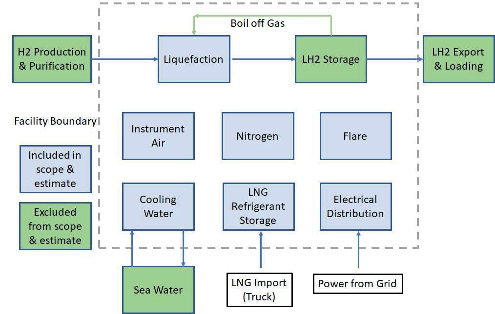
Bill Howe and Geoff Skinner, Gasconsult Ltd, alongside James Primrose, McDermott, discuss the importance of optimising hydrogen liquefaction to support the development of the sector.
26 The safe decarbonisation of combustion
Increasing the efficiency of both new and existing steam methane reformers (SMRs) is an essential consideration for decarbonising operations. Tim Tallon, AMETEK Process Instruments, and James Cross, AMETEK Land, discuss two ways in which this can be done.
31
Driving a safe future
Jørg Aarnes, DNV, Norway, describes methods to ensure safety during the hydrogen revolution.
34
Assisting transformation
Jens Voss, ROSEN Group, introduces the diagnostic solutions that are available for supporting future fuel pipelines.
38
Compression ‘Down Under’
Brian Mason and Chirag Sehgal, Siemens Energy, discuss how Australia is preparing for the hydrogen economy by way of retrofitting existing compression and transportation
44 The challenge of atmospheric hydrogen compression
Octavian Partenie, Pascal Pasman, Svitlana Snelder and Theo Peperkamp, Howden, explain why it can be challenging to design reciprocating compressors for hydrogen produced at atmospheric pressure.
48 Getting a sense of hydrogen
David Meyers, H2scan, USA, discusses the importance of hydrogen sensing within the emerging hydrogen economy.
53 A means to monitor quality
Global efforts to protect the environment have increasingly focused on lowering carbon emissions. Dr. Florian Adler and Jim Belanger, Process Insights, suggest that the key to meeting this challenge lies in replacing fossil fuels with alternative, renewable fuel sources, particularly to power vehicles.

57 Getting the green light
Allan Rushforth, First Hydrogen, UK, describes how green hydrogen is supporting the UK’s transport sector on the path to becoming a net zero industry.
61 Withstanding hydrogen
Dr. Thomas Gallinger and Simon Schlei, TÜV SÜD Industrie Service, discuss the testing methods behind determining whether components and materials are compatible with hydrogen.
64 The digital delivery of a complex hydrogen network
Roy Calder, AVEVA, UK, explains the importance of developing digital environments to support the success of hydrogen projects.
69 The digitisation of hydrogen filling stations
Mathias Kurras, Maximator Hydrogen GmbH, Germany, explains how digitisation makes hydrogen filling stations safer, more efficient, and continuously available.
72 Big data to support big decisions
Lukas Strohmeier, Delphi Data Labs GmbH, Austria, explains how big data helps companies to identify the right customers, partners or suppliers in the emerging green hydrogen economy.
This month's front cover
H2scan’s proven sensing technology, based on R&D, engineering and production excellence, helps to ensure the safe and effective operation of the hydrogen economy. Turn to p. 48 to learn why sensors are vital for hydrogen reliability and safety.
Copyright© Palladian Publications Ltd 2023. All rights reserved. No part of this publication may be reproduced, stored in a retrieval system, or transmitted in any form or by any means, electronic, mechanical, recording or otherwise, without the prior permission of the copyright owner. All views expressed in this journal are those of the respective contributors and are not necessarily the opinions of the publisher, neither do the publishers endorse any of the claims made in the articles or the advertisements.
@HydrogenReview like join Global Hydrogen Review @Hydrogen_Review follow
Join the conversation
Spring 2023
MORE BUSINESS LESS CARBON NATURAL GAS, FUTURE READY.
The case for blue hydrogen is clear.
Topsoe is ready to help you scale up and bring emissions down using natural gas resources.
Take the lowest energy route to ultra-low carbon intensity hydrogen with Topsoe’s industry-leading reforming technologies and integrated carbon capture.
Find out how: topsoe.com/bluehydrogen
Managing Editor James Little james.little@palladianpublications.com
Senior Editor Callum O'Reilly callum.oreilly@palladianpublications.com
Deputy Editor Bella Weetch bella.weetch@palladianpublications.com
Sales Director Rod Hardy rod.hardy@palladianpublications.com
Sales Manager Chris Atkin chris.atkin@palladianpublications.com

Sales Executive Sophie Birss sophie.birss@palladianpublications.com
Production Manager Kyla Waller kyla.waller@palladianpublications.com
Events Manager Louise Cameron louise.cameron@palladianpublications.com
Events Coordinator Stirling Viljoen stirling.viljoen@palladianpublications.com
Digital Content Assistant Merili Jurivete merili.jurivete@palladianpublications.com
Digital Administrator Leah Jones leah.jones@palladianpublications.com
Admin Manager Laura White laura.white@palladianpublications.com
As I write this, we have just come to the end of the 2022/2023 ‘film awards season’. One of the movies nominated for a prestigious Academy Award was ‘Glass Onion: A Knives Out Mystery’. The murder mystery adventure, which features a star-studded cast including Daniel Craig, Edward Norton and Janelle Monáe, was up for the ‘Best Adapted Screenplay’ award. And although the Oscar in this category eventually went to ‘Women Talking’, the writers of ‘Glass Onion’ can take comfort in the commercial success of the film, which reportedly racked up an estimated 35 million views within three days of its release on Netflix.
For those of you who haven’t seen the film, I’ll briefly explain why I am talking about it (warning: some spoilers ahead). As you may have already guessed, Glass Onion centres around the murder of a key character, and the audience is left guessing ‘whodunnit’ throughout. But aside from dramatic plot twists and red herrings aplenty, the story revolves around a conflict between the characters over the commercialisation of a fictional hydrogen-based fuel made of abundant seawater called ‘Klear’. Now, as you would expect from a Hollywood blockbuster, the line between fantasy and reality is more than a little blurred. For starters, Klear is a solid hydrogen fuel that resembles a crystal, which can be slipped into your pocket. In reality, pure hydrogen would need to be -260˚C (-434˚F) to exist in a solid state, which would make placing it in your pocket pretty difficult.
There are plenty of other misconceptions about hydrogen scattered throughout the film, including a somewhat lazy reference to its role in the 1937 Hindenburg disaster, and exaggerations about its propensity to leak compared to other fuels. And the film’s final scene leaves viewers in little doubt about the combustibility of the fuel, perpetuating the myth that hydrogen is inherently more dangerous than other hydrocarbon fuels. If you’d like to read more about the hydrogen plot holes throughout the film, there are plenty of articles available online (and I have included links to a couple at the bottom of this page).
However, these misconceptions are not helpful to hydrogen’s reputation, especially at a time when the sector is really starting to gain momentum. As an article from Hydrogen Forward (a coalition of companies working across the hydrogen value chain) summarises: “Hydrogen has been used throughout society for decades, complying with safety and logistics standards to enhance public safety. If net zero is to be achieved, building trust in all climate solutions, including hydrogen, will be required.”
And that is precisely our aim at Global Hydrogen Review. This issue is full of fascinating articles on topics including how to ensure safety during the hydrogen revolution (p. 31), and the vital role of sensors for hydrogen reliability and safety (p. 48). Other key themes throughout this issue include the green vs blue hydrogen debate (pp. 4 – 19), hydrogen liquefaction technology (p. 20), future fuel pipelines (p. 34), compressors (pp. 38 – 47), digitalisation (pp. 64 – 72), and much more.
Editorial/advertisement offices: Palladian Publications
15 South Street, Farnham, Surrey
GU9 7QU, UK
Tel: +44 (0) 1252 718 999 www.globalhydrogenreview.com
I’d also like to invite you to attend our annual Global Hydrogen Conference on 20 April. This year’s virtual conference will be full of interesting presentations from the likes of Cornwall Insight, Honeywell, Topsoe and Svante. You can find out more, and register for your free space, by clicking here.
• https://www.hydrogenfwd.org/spoilers-glass-onions-klear-hydrogen-fuel-is-clearly-the-stuffof-hollywood-fiction/
• https://www.plugpower.com/shattering-hydrogen-myths-in-glass-onion-a-knives-outmystery/
Callum O'Reilly Senior Editor
Producing low-carbon hydrogen at competitive costs is one of the key factors behind achieving net zero emissions. Not only could it be used as a replacement for fossil fuels in hard-to-decarbonise industries such as steel production, but it may also eventually be used as fuel for space heating and vehicles, as well as for the creation of sustainable aviation fuels (SAFs).
Today, the most common form of hydrogen that is produced is grey hydrogen, but this emits around 1 billion t of carbon dioxide (CO2) – 2% of global CO2 equivalent (CO2e) emissions. While industries and governments are exploring lower-carbon solutions such as blue and green hydrogen as long-term tools that can improve security of energy supply, and reduce reliance on Russian gas, there is considerable debate over what is the most cost-effective and environmentally-attractive production route.
Blue hydrogen is not zero-carbon because not all carbon is captured, and methane leakages during gas production can be sizeable contributors to global warming. Therefore, green hydrogen seems more environmentally-advantageous than blue – and ideally, that would be the case. However, in certain circumstances, green hydrogen emissions can be twice those of grey hydrogen. If the goal is decarbonisation, industries and governments need to be thoughtful as to when and where green hydrogen projects are deployed if they are to successfully lower emissions and increase security of supply.
Green hydrogen: the full-system carbon footprint and economics
Green hydrogen is produced by electrolysing water using electricity generated by renewables. Besides producing molecules of hydrogen, the principal byproduct is oxygen.

4
Chris Warnes, Oliver Wyman, UK, offers a perspective on scaling low-carbon hydrogen production.
Today, green hydrogen production is expensive, but with the falling cost of renewables and improved electrolysers, there is an expectation that it will become cost-competitive with other fuels over time. Long-term, it is the most environmentally-friendly approach to producing low-carbon hydrogen.
However, this is not necessarily the case over the medium-term. If green electricity is diverted from the grid for hydrogen production, then this has its own environmental implications. Where baseload electricity is taken from the grid and used to produce hydrogen, this electricity must be replaced by incremental power generation. As existing renewables are already running at full power, the incremental power typically must be produced from natural gas-powered generation or, in many markets including Germany and China, coal – the most carbon-intensive fossil fuel.
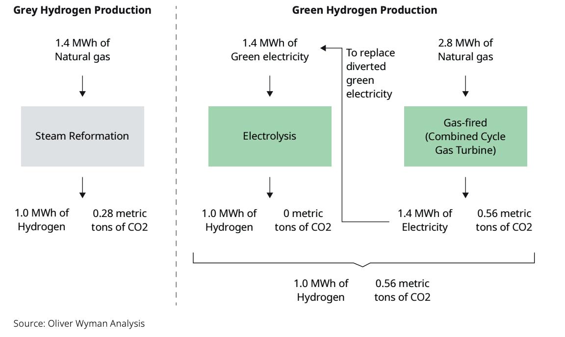
Figure 1 examines the relative environmental impacts of grey and green hydrogen, in the case where the electricity is diverted from the grid and needs replacing with natural gas-fired power generation. Only 1.4 MWh of gas is required to produce 1 MWh of grey hydrogen, with an associated 0.28 t of CO2 emissions. To produce the same amount of green hydrogen, 2.8 MWh of natural gas is burned in a gas-fired power plant (combined cycle gas turbine) to generate the electricity to replace the diverted green electricity, resulting in a 100% increase in carbon emissions overall, to 0.56 t. If the electricity is generated from coal, then the total emissions would be over 1 t.
On a full-power-system basis, both paths start with gas. However, by going through two process steps, the green hydrogen is inherently less efficient, with typical conversion losses for gas-fired power stations of 50%, followed by a further 30% loss at the electrolyser, resulting in

5
a cumulative 65% loss, whereas steam reformation losses are of the order of 30%.
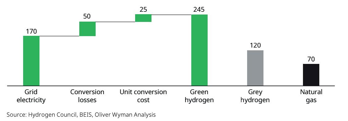
In addition to the questions surrounding decarbonisation benefits, green hydrogen appears to be economically-inefficient, since its production requires electricity, a high-value product, to make a generally lower-value product: hydrogen. For example, markets currently indicate prices of around US$170/ MWh for electricity, and US$70/ MWh for natural gas in Europe in 2025. Once the cost of the electrolyser conversion is factored in, converting grid electricity to green hydrogen results in a hydrogen cost of around US$245/MWh (see Figure 2), compared to grey hydrogen at around US$120/MWh. Using green hydrogen at US$245/MWh to replace natural gas (at US$70/MWh) is even less efficient. This is also the case when looking at prices that prevailed before the current energy crisis.
A standalone green hydrogen plant receiving electricity from an offshore wind farm can produce green hydrogen for a total cost of around US$130/MWh – considerably cheaper than green hydrogen from the grid. However, this effectively relies on the wind farm selling the electricity to the electrolyser at around US$60/MWh, which is not a logical choice when the alternative is to sell the electricity to the grid at US$170/MWh.
If hydrogen is produced from excess green electricity that has no other use, or from a standalone renewable project that cannot be connected to the local grid because of transmission constraints, then this is clearly a green product. However, in many markets today, increasing electricity demand to produce green hydrogen will result in an overall
increase in gas or coal demand and carbon emissions, as a gas-fired or coal-fired generation plant is required to supply the increased electricity demand.
With strong renewable growth predicted across the world, periods of excess low-carbon electricity will increase. The UK’s department for Business, Energy, and Industrial Strategy (BEIS) estimates that in a market with excess electricity for 25% of the year, truly green hydrogen can be produced for a cost of US$80/MWh by only running the electrolyser during the periods of excess electricity, when electricity prices will be close to zero. However, while the supply of renewable energy is growing, so too is the demand for it. A number of other market developments are likely to limit the growth of periods of excess low-carbon electricity:
y Increased demand for power: the growth in the number of electric vehicles (EVs) and heat pumps will increase overall demand.
y Changing customer demand patterns: energy suppliers are encouraging demand to shift to periods of high renewables production by way of lower electricity rates during this time.
y Increased interconnection between national power grids: this is diversifying the renewable supply, reducing the likelihood that any one particular market will have excess electricity. Connecting the UK market with Norway, for instance, makes it possible for the UK to effectively use Norway’s large hydropower capacity as long-term storage, importing power when the wind is not blowing and exporting excess renewables during high wind, allowing Norway to conserve future hydropower resources.
y More battery storage: growth in lithium-ion batteries offers a far more economical solution for any renewable over-supply than green hydrogen production for short periods of over-supply, with only about a 15% efficiency loss and a lower capital cost per megawatt than an electrolyser. With battery costs falling rapidly, their deployment is expected to scale up rapidly, allowing their economic use case to extend into longer periods of over-supply.
� Battery research and development (R&D): alternative battery technology is receiving significant R&D investment, encouraging the development of longer-duration batteries, such as flow batteries, and creating competition with green hydrogen for excess renewable electricity.
Together, these trends suggest that the potential of truly green hydrogen over the next two decades may be lower than believed. Thus, it is important to look more seriously at blue hydrogen to fill the gap in the meantime.
Blue hydrogen: the full-system carbon footprint and economics
Blue hydrogen is produced by reformation of natural gas, through heating natural gas to high temperatures using steam methane reformation (SMR) or auto thermal reformation to convert it into hydrogen and CO2. The concentrated CO2 is then captured and stored. Typically, the heat to drive
6 Spring 2023 GlobalHydrogenReview.com
Figure 1. Why green hydrogen can be more carbon-intensive than grey.
Figure 2. Green hydrogen – projected production costs vs grey hydrogen and natural gas in 2025 (US$/MWh).
ACCELERATING BLUE HYDROGEN TOGETHER
The world’s energy systems are changing; and hydrogen is becoming a key part of the future energy mix. With that need for very large volumes of hydrogen on the horizon, Shell Catalysts & Technologies has developed a low cost, high capacity way to match those production needs via the Shell Blue Hydrogen Process. The processes bring together several proven technologies to deliver 500 te/day of hydrogen with >95% CO2 capture rate at the lowest levelized cost. It’s a hydrogen solution designed to help decarbonize hard to abate industries, lower the CO2 footprint of heavy transport, and reduce home heating emissions.
Learn more at http://catalysts.shell.com/bluehydrogen
the process is also produced using natural gas, creating a secondary, more dilute CO2 stream. An average capture efficiency of approximately 90% over both streams is expected to be achievable.
Presently, blue hydrogen is expected to have a lower production cost than green hydrogen. The key concern with blue hydrogen is its reliance on fossil fuel production and the resulting environmental risks by way of methane emissions associated with the gas production, and the less than 100% capture of CO2
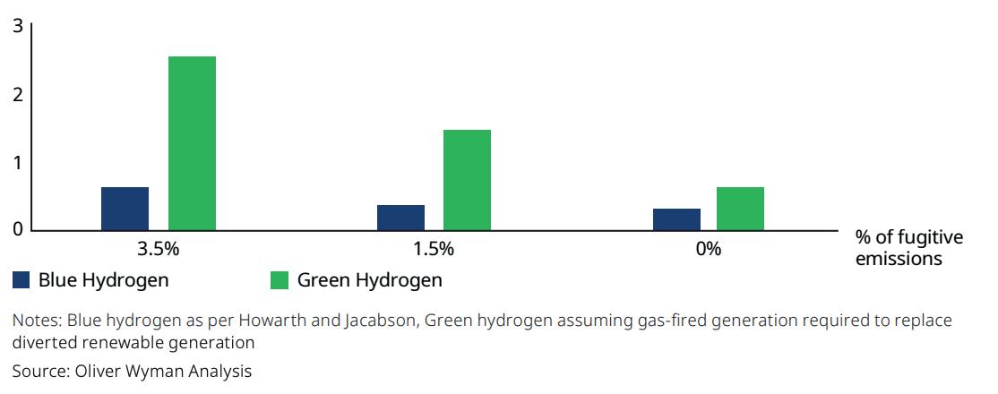
Methane has a much higher greenhouse gas (GHG) impact than CO2 – about 86 times more when measured over a 20-year period. So, only small levels of methane leakage can increase the carbon footprint significantly. In 2021, Professor Robert Howarth of Cornell University, and Professor Mark Jacobson of Stanford University estimated the level of fugitive emissions at 3.4% (based on measurements in the US) and calculated that at this level of emissions, blue hydrogen has a similar carbon footprint to grey. They concluded that the world should focus on green hydrogen. However, by applying the whole-system concept, it is clear that green hydrogen is often effectively generated from gas-fired power, so fugitive emissions can be as much of a challenge for green hydrogen as they are for blue.
Figure 3 shows the relative GHG emissions levels of green vs blue hydrogen at differing fugitive emission level assumptions. The 3.4% appears a rather high estimate as to the long-term level of fugitive emissions from gas production. For example, the Oil and Gas Climate Initiative, a CEO-led council of 12 leading oil and gas producers that support the 2015 Paris Agreement targets, reported 0.2% of fugitive emissions in 2020. As demonstrated in Figure 3, the carbon footprints of both green and blue hydrogen are highly sensitive to these assumptions. However, in all cases, blue hydrogen’s footprint is significantly smaller than green hydrogen, where green hydrogen is produced from baseload power taken from the grid.
This analysis reinforces the importance of tight control of fugitive emissions for gas in all areas, but it should not be used as an argument against blue hydrogen.
The key challenge for blue hydrogen: public acceptance
While commercial-scale carbon capture plants have been envisaged for more than 15 years, few currently exist outside
of the oil and gas industry. Today there is some 40 million tpy of worldwide carbon capture and storage (CCS) capacity, representing about 0.1% of global carbon emissions, of which 80% is used to support enhanced oil recovery rather than primarily for carbon abatement. This is despite all of the key technology elements being in place, and cost estimates for this kind of carbon abatement are similar to other well-supported low-carbon technologies.
Blue hydrogen and carbon capture have faced considerable political challenges, with some viewing them as a smoke screen to enable the continued production of fossil fuels. Consequently, governments have been slow to put in place the financial and legal support frameworks that investors need. Prices in existing carbon markets, such as Europe, have been insufficient to incentivise CCS on their own.
Today, support for blue hydrogen is growing, with several countries now planning blue hydrogen development projects – a number of which are situated close to the North Sea, with access to natural gas and offshore storage locations. However, many are also prioritising strong green hydrogen development. For example, the EU’s hydrogen strategy envisages positive growth in green hydrogen to deliver decarbonisation and increase energy security.
Conclusion
The view that green hydrogen is lower-carbon than blue hydrogen is an oversimplification. Longer-term, once electricity is predominately produced from renewable electricity and there are significant periods of excess renewables with no market on the power grid, then this will be the case. But in the short- and medium-term, policymakers and hydrogen generators need to understand the nuances of when green hydrogen is truly green, and to not discount blue hydrogen prematurely before its economics and environmental performance have been fully tested.
Done incorrectly, large-scale deployment of green hydrogen production will result in an increase of emissions and gas consumption vs continuing to use grey hydrogen. This will only cease to be the case when significant excess renewable electricity is produced that can be dedicated to the production of green hydrogen.
Renewable generation capacity is scaling rapidly worldwide, yet there are limitations across the supply chain as to how quickly capacity can increase. Consequently, renewable power should initially be deployed in situations where it delivers the most effective carbon abatement, i.e. decarbonising existing grids, supplying additional power required for EVs and heat pumps, and providing growing electricity demand in developing economies – before seeking to convert it to green hydrogen.
Given the challenges facing green hydrogen, the need to scale blue hydrogen cannot afford to be overlooked.
Note
8 Spring 2023 GlobalHydrogenReview.com
• All price data in this article is valid as per October 2022.
Figure 3. Blue vs green hydrogen – GHG emissions with differing fugitive methane assumptions (t CO2 per MWh).
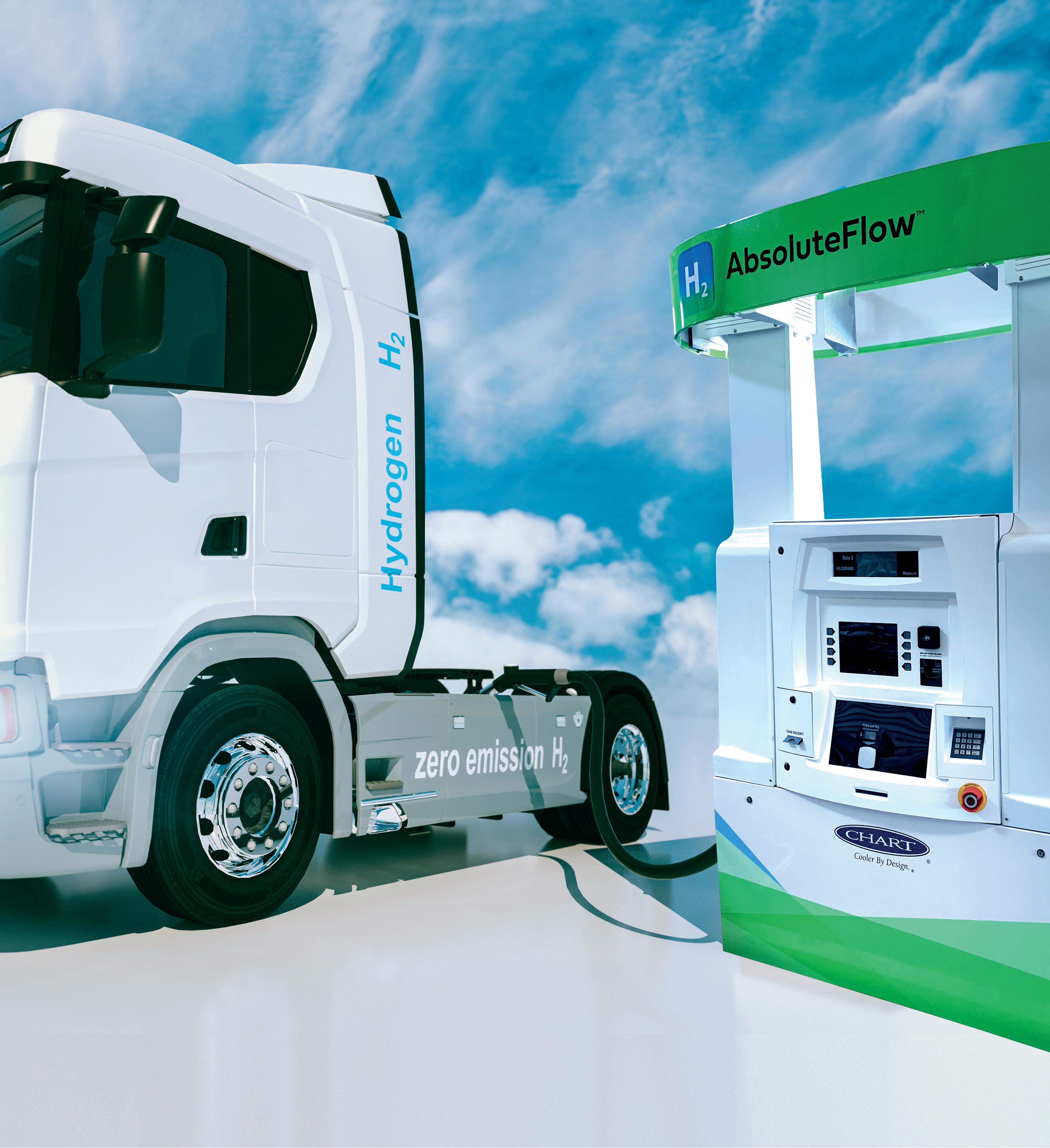
Chart’s HLH2 vehicle fuel systems provide greater range and payload advantages using liquid hydrogen storage and an integrated heat exchanger for Fuel Cell Electric Trucks (FCETs).
HLH2 vs. H35/H70
• Lighter Weight
• Smaller Footprint
• Easier to Install
• Faster Fill Times
• Customized Integration with Truck Manufacturer’s Fuel Cell Engine
www.ChartIndustries.com/Hydrogen hydrogen@chartindustries.com
Americas: +1 800 400 4683
Germany: +49 (0)2823 328 224
China: +86 519 8596 6000
Chart’s liquid hydrogen fuel stations allow for quicker fueling of vehicles with more dense liquid hydrogen, using simpler equipment and requiring less infrastructure investment.
Scan to download our
brochure
Rajesh D. Sharma, Schneider Electric, discusses how and why hard-to-abate sectors should consider transitioning to green hydrogen, and details the three challenges associated with this shift.

10
Carbon dioxide (CO2) emissions from energy combustion and industrial processes accounted for close to 89% of energy sector greenhouse gas (GHG) emissions in 2021. CO2 emissions from gas flaring accounted for another 0.7%. Beyond CO2, fugitive and combustion-related methane emissions represented 10% of the total, and combustion-related emissions of nitrous oxides (NOx) 0.7%, according to the IEA’s report, ‘Global Energy Review: CO2 Emissions in 2021’.1
Today, fossil-based energy is the global economy’s fuel. It is an enabler, but it also comes with the inherent challenge of associated GHG emissions. It is important to continue innovating technology that will sustain both our planet and society.
Over the decades, renewable forms of energy have been encouraged and new technologies have been developed. The world, however, is still facing many challenges in terms of transitioning from fossil fuel to carbon-neutral energy – especially with the current energy

crisis demanding more sustainable forms of energy.
Although we have been producing hydrogen for industrial processes for a long time, the majority of such production is by way of using fossil fuels. Today, in order to meet the current demand for hydrogen – which is estimated to be approximately 90 million t – 6% of global natural gas and 2% of global coal are used, according to the World Bank.2
Green hydrogen as a vector for renewable electricity generation has been touted as a potential substitute to fossil fuels, mainly in hard-to-abate sectors, which will help us to accelerate the race to reducing our carbon footprint. The growing popularity behind this innovative solution stems from how it can facilitate a transition away from hydrocarbons. Made with renewable energy, it will be an essential contributor to effecting this necessary change. Determining how to achieve cost-effective production, however, presents a formidable challenge.
11
The desire to move toward green hydrogen is real, but the transition is faced with three critical challenges.
Improving knowledge, design, and engineering results
Finding the path forward towards efficient green hydrogen production requires new technologies and new thinking. Moreover, many individuals still lack the necessary training and skills required to support the hydrogen economy. Integrated engineering using a digital twin and process modelling are currently key technology solutions for green hydrogen production and design. However, as production continues to evolve, technology of this nature should continue to be evaluated and improved.
Considering that we can reuse knowledge captured, it is essential to use a digital design tool that can embed such knowledge of complex chemical and physical processes. This type of digital design tool can assist in decision making throughout all phases of project delivery and plant optimisation activities. As such, a digital twin becomes a necessary tool to successfully design and operate green hydrogen production and distribution facilities. To increase efficiency and lower risk, manufacturers may now incorporate a digital twin platform to manage all phases of an asset’s lifespan – from engineering and design, through to financing, building and operation.
By integrating design and construction processes on a single platform, companies can work with global enterprise footprints and remote work models. An integrated, single platform enables engineers from anywhere in the world to explore all dimensions of a potential project and quantify its impact on sustainability, feasibility and profitability.
In the modern industrial organisation, every aspect of the production process is monitored and analysed with sensors that are capable of generating hundreds of thousands of data points. When this information is aggregated across siloed departments and regions, it improves visibility from the edge to the business, while promoting integration and collaboration across functional departments. Integrated power and process systems help to improve day-to-day activities and processes. A system such as this reveals operational inefficiencies and enables critical decisions and changes that directly impact profitability.
Ensuring safety and efficiency; improving operations
One of the main advantages of hydrogen is its high energy content per mass. However, this poses a significant security risk. Electrolysis produces hydrogen and oxygen. Hydrogen has a very broad flammability range: a 4 – 74% concentration in air, and 4 – 94% in oxygen. Therefore, preventing air or oxygen from mixing with hydrogen inside confined spaces is very important. A small leak from a pipe or storage vessel can easily ignite, resulting in a fire or explosion.
It is inevitable, then, that proper handling of hydrogen along the value chain will be an essential consideration. A robust design and operation process will be crucial at all stages: production, storage, transportation (by pipeline, truck, or rail), and end use.
While hydrogen is a not a toxic gas, it is still highly flammable and relatively complex to de-risk. Moreover, the severity and frequency of damage related to hydrogen, for example, is dependent on the extent to which the gas has been blended with other materials. In short, hydrogen should be consistently monitored through a combined safety, power, and process control system. On top of the safety regulations required during production, the massive consumption of power needed for green hydrogen production also makes power safety and efficiency critically important.
Combined power and process safety systems help reduce the likelihood of such incidents. A well-designed safety system can eliminate all risks associated with process failures.
Injuries, fatalities, or damage to infrastructure can negatively impact public acceptance of hydrogen and ultimately slow the energy transition. Process safety is therefore an important element to be considered when designing and operating hydrogen production plants.
Reducing downtime is a constant challenge for industrial companies, and the same is true for hydrogen production plants. Early warnings and diagnostics of equipment performance are essential to ensuring that equipment is operating at full capacity when needed, and to prevent mechanical or process failures. Artificial intelligence (AI) is making a big difference in helping asset-intensive businesses to reduce equipment downtime and increase reliability, while lowering operating and maintenance costs. Tools such as predictive analytics and advanced process control can help producers to achieve maximum plant uptime and efficiency.
On the other hand, when operating hydrogen production with electrolysis, voltage surges or sags, deviations in power quality, as well as supply interruptions, negatively impact production throughput and product quality. Additionally, inadvertent trips due to power shortage, generation overload and other electrical constraints need to be quickly analysed from correlated sequences of events across both electrical and process domains. Quickly understanding how and why these events occur is crucial to maintaining operation value and uptime.
A combined power and process strategy from design into the engineering, operation and maintenance stages improves the efficiency of green hydrogen production, resulting in savings across the complete life cycle of the asset. Digital twins, combined power and process control systems, integrated safety, and predictive analytics should be considered by green hydrogen developers as ‘must-have’ solutions.
When multiple systems control a process, manage electrical equipment, or provide security to a facility, it becomes more difficult for each operator to simultaneously maintain tight and efficient control over each process, while maximising performance. Energy-intensive industries such as the hydrogen industry must strive to boost uptime, maximise throughput, and reduce total expenditures (TotEx) by lowering the end-to-end life cycle costs of the assets. Integrated digitised systems offer additional benefits, including faster commissioning, less cabling, simpler maintenance, and a reduced footprint. With the potential to improve process and energy efficiency while lowering risks to operational continuity, digitised process and power control solutions make sound business sense in an unpredictable environment.
12 Spring 2023 GlobalHydrogenReview.com
Invisible. Invaluable.
You can’t see hydrogen, a zero-carbon fuel that perfectly complements— and even accelerates–the integration of renewable energy sources for ammonia producers. But the impact of this essential element creates an invaluable path forward towards decarbonization, supporting expansion and energy transition for multiple energy consumers, including maritime, industrial, and power generation facilities.
Black & Veatch delivers on:
• Safe, reliable, and informed innovation across the hydrogen value chain

• Solutions across green hydrogen for power generation and storage, as well as the processing of blue hydrogen with carbon capture technology
• Diversity of experience and depth of knowledge, offering practical insight and access to the right resources at the right time
Let’s find ways to help you.
Developing and implementing requirements for green certification
It is very likely that producing renewable energy close to the green hydrogen production facility may not be possible in some cases. It is also likely that some independent renewable energy producers may want to sell their produced energy to green hydrogen producers.
In such cases, the power will be transmitted to the green hydrogen production facility through the grid. When grid power is used for green hydrogen production, it becomes important for the producer to know that the produced hydrogen is generated from green electrons, and this information should be made available to hydrogen users. Such certification will be necessary for any rebate that hydrogen users may receive from authorities. Blockchain is going to be the solution for these certifications, and this will have to be adopted by power utility companies, hydrogen producers, and users.
Conclusion
New technologies such as green hydrogen will pave the way in the move from fossil fuels towards renewable energy sources. Leveraging the experience that has been gathered in the energy and chemicals industry can help operators to improve project design and operations, ultimately providing an opportunity to create a cleaner ecosystem.
There is significant investment to be made in green hydrogen production in the coming years. According to DNV’s forecast, global expenditure on hydrogen generation for energy will be US$6.8 trillion by 2050, with an additional US$180 billion for hydrogen pipelines and US$530 billion for the construction and
operation of ammonia terminals.3 The International Renewable Energy Agency (IRENA)’s ‘2021 World Energy Transitions Outlook’ estimates that hydrogen and its derivatives will account for 12% of final energy consumption by 2050, with two-thirds coming from green hydrogen (made with clean electricity) and one-third from blue hydrogen (made from fossil fuels and using carbon capture).4
Governments also need to create policies and regulatory frameworks that encourage investments. Capacity building and the provision of technical assistance to governments, particularly in emerging and developing countries, are essential to developing these regulations and ensuring their enforcement and compliance. It is also necessary to have a globally-recognised definition of green hydrogen and methods to guarantee and certify the origin of the fuel. The need to help workers develop the skills required in this booming sector is also essential, especially considering net zero goals and the energy transition agenda.
References
1. ‘Global Energy Review: CO2 Emissions in 2021’, IEA, https://www. iea.org/reports/global-energy-review-co2-emissions-in-2021-2
2. ‘Green Hydrogen: A key investment for the energy transition’, World Bank Blogs, (23 June 2022), https://blogs.worldbank.org/ ppps/green-hydrogen-key-investment-energy-transition
3. ‘Energy Transition Outlook 2022’, DNV, https://www.dnv. com/energy-transition-outlook/download.html?utm_ source=Google&utm_medium=Search&utm_campaign= eto22&gclid=CjwKCAiA5sieBhBnEiwAR9oh2k94tsRKebN_ GxIFYhSgZ57zwqevQ94BFKjziBgxa0h4tVpX7L6mvBoC3_wQAvD_BwE

4. ‘World Energy Transitions Outlook’, IRENA, https://www.irena.org/-/ media/Files/IRENA/Agency/Publication/2021/Jun/IRENA_World_ Energy_Transitions_Outlook_2021.pdf
Global Hydrogen Review Online

Visit our website today: www.globalhydrogenreview.com Home to the latest hydrogen news, analysis and events
Creating a robust, sustainable and safe hydrogen value chain at scale will require significant efforts and infrastructural investments across a broad spectrum of end users, industries and regions. Producers, end users and everyone in between must continue innovating and collaborating to commercialise hydrogen technologies at scale.
As the International Energy Agency (IEA) notes, current hydrogen production is primarily based on fossil fuel technologies. More than one-sixth of global hydrogen supply comes from ‘byproduct’ hydrogen, mainly from facilities and processes in the refining and petrochemical industry. Low-emission production represents less than 1% of hydrogen from 1999 to 2021.1
To achieve net zero objectives, it is estimated that more than half of the hydrogen produced globally by 2030 needs to be low-emission hydrogen.
However, there is a wide gap between the world’s high-emission hydrogen production today and the amount of low-emission hydrogen needed.
The current worldwide production of hydrogen utilising fossil fuels without carbon capture, utilisation and storage (CCUS) is 77 million tpy. Another 16.5 million tpy is produced as an industrial byproduct, mainly from refining and petrochemical processes.1 Reaching net zero objectives calls for action surrounding how hydrogen is made from fossil fuels without CCUS:
� Going forward, it is expected that approximately two-thirds of low-emission hydrogen production will be based on electrolysis to make green and pink hydrogen.
� A further third will be produced from fossil fuels with CCUS, to make blue hydrogen.
� The world will need to construct more than 700 GW of electrolysers for green and pink

15
Viswadeb Ganguly and Adrienne Moreno, Flowserve, USA, explain why significant investment in blue hydrogen infrastructure is required to help accelerate the transition to net zero.
hydrogen, which is equivalent to a hydrogen output of 128 million tpy.
� Production of another 37 million tpy of blue hydrogen will require the construction of plants using fossil fuels with CCUS or with advanced, low-carbon-intensity technologies.
Canada and the US lead in the production of blue hydrogen from fossil fuels with CCUS, with more than 80% of global capacity production. Today, 16 projects for producing hydrogen from fossil fuels with CCUS are operational, producing 0.7 million tpy of blue hydrogen.2
Globally, about 50 CCUS projects are under development and could increase the annual blue hydrogen production to more than 9 million t by 2030.2 Most of these are located in the Netherlands and the UK.
Blue hydrogen: the proven, available choice
Blue hydrogen represents the best low-carbon option available today because its production can be increased with proven and widely-available CCUS technologies or other advanced, low-carbon-intensity technologies.
Scaling up hydrogen production and consumption will be critical to reducing the cost at the point of usage, which is largely linked to the costs of production, storage and transportation. However, until a large-scale, cost-effective green hydrogen economy is developed, blue hydrogen can create a low-carbon market architecture. This will facilitate its end use acceptability as a transition energy carrier, and help to stagger the investments of storage and distribution over time.
In the near-term, the following is required:
� CCUS technological improvements in reliability, efficiency and cost.
� Gas compression, transportation and storage infrastructure deployment.
� The deployment of hydrogen technologies to support growing end use applications and cost-competitiveness.
� Supportive governmental policies and economic incentives to minimise investment risks and mandate emissions reductions.
Building cost-effective collection and distribution hubs
Hydrogen may one day be among the low-cost options to help decarbonise industrial heating, heavy-duty transportation, off-road vehicles, and off-grid equipment such as generators. Today, however, most hydrogen is consumed in-situ or near its point of production. Typical applications are in oil refining, ammonia (NH3)/fertilizer production, chemical processing and steelmaking.
Total hydrogen demand from all industrial use is expected to increase 44% by 2030, with low-carbon hydrogen becoming ever more important, the IEA reports.
Moving hydrogen into a dominant position in the world’s energy mix will require the development of centralised hubs in the initial stages, to take advantage of economies of scale. These hubs will deliver low-carbon hydrogen to nearby end users while also minimising or eliminating emissions.
Public policy and governmental support can encourage this transition. The US Department of Energy (DOE) is launching major initiatives3 such as:
� US$8 billion for regional hubs that will expand the use of clean hydrogen in the industrial sector.
� Another US$500 million for clean hydrogen manufacturing and recycling initiatives to support equipment manufacturing and strong domestic supply chains.
New distribution networks that include pipelines, ships and tank trucks to enable the delivery of hydrogen between regions will also be necessary. Storage options for liquid and/or alternate gaseous hydrogen will need to be developed. Additionally, NH3 and methanol (CH3OH) are extremely efficient carriers of hydrogen in their native forms. The hydrogen can be further converted to NH3 and CH3OH to be transported for later conversion into hydrogen, or used in its converted form. NH3 and CH3OH are easier to transport and store because their energy densities per unit volume are greater than pure hydrogen and they do not require extreme cryogenic conditions for storage.
Figure
Fuelling hydrogen growth with policy changes
Blending hydrogen into the existing natural gas infrastructure can offer national and regional benefits for energy
16 Spring 2023 GlobalHydrogenReview.com
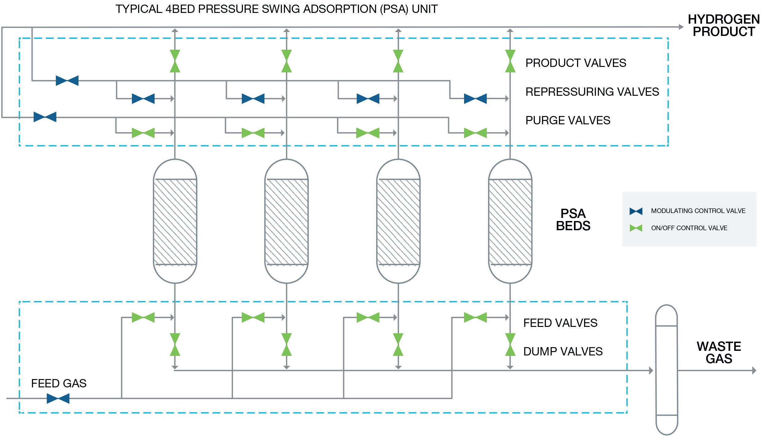
1. A typical large-scale hydrogen plant’s pressure swing absorption (PSA) unit is vulnerable to production constraints when control valves fail or deviate from expected behaviour. Increasing uptime by even 1% can lead to a significant positive impact on throughput. Flowserve offers RedRaven, a predictive maintenance solution that provides remote sensing, condition monitoring and analytics to enable plant operators to identify and address issues before they disrupt production.
Hydrogen Compression
Turn to Elliott Group for operational flexibility in hydrogen applications.

Elliott’s Flex-Op® Hydrogen Compressor features flexible, configurable, and economical compression options for hydrogen applications. Designed with proven Elliott compressor technology, the Flex-Op’s compact arrangement of four compressors on a single gearbox maximizes compression capability with enough flexibility to run in series, in parallel, or both. Who will you turn to?
n Learn more at www.elliott-turbo.com
The World Turns to Elliott COMPRESSORS |
|
CRYODYNAMICS®
GLOBAL
TURBINES |
SERVICE
transportation, resiliency and emissions reductions. End users of natural gas can then burn the blend to generate power and heat.
Hydrogen can add value to hard-to-abate industrial sectors such as steel and cement production, while acting as a bridging energy carrier that supplements and accelerates the integration of renewables into the energy system.
For that to happen at a pace necessary to meet climate goals, governmental policies will need to make changes. These might include auctions, mandates, quotas and hydrogen-specific requirements in public procurement. Requiring hydrogen use can help industry de-risk investment and improve the economic feasibility of low-emission hydrogen, according to the IEA.
The eventual goal will be a wider deployment of green hydrogen production by renewable solar and wind power. However, that is a long-term ambition. Green hydrogen development needs near-term expansion of blue hydrogen to increase market demand, expand infrastructure, and improve the financial feasibility of the hydrogen economy.
To that end, the US government has established its ‘Hydrogen Shot’ effort to reduce the cost of clean hydrogen by 80% to US$1/kg in one decade.3 The US Department of Energy (DOE) has US$28 million available for research as well as engineering design projects to advance clean hydrogen in industrial uses, and in the transportation and electricity sectors.3
There is also what the DOE calls ‘H2 Matchmaker’.4 This resource can help clean hydrogen producers, end users and others to find opportunities to develop networks of production, storage and transportation infrastructure. The H2 Matchmaker online tool enables hydrogen producers and end users to connect with others nearby.
These are examples of the policies, research and funding that will be needed to encourage and accelerate the transition to hydrogen. Adopting the right technologies and further critical technological advancements, along with significant financial investment, are what is needed for large-scale hydrogen deployment in the US. Other nations have also begun to
prioritise hydrogen and fuel ammonia projects. Examples include:
� The Hydrogen Public Funding Compass5 from the EU provides information regarding the €9.3 billion (US$9.6 billion) of funding that is available for hydrogen projects, from 15 countries.6
� Australia plans to spend AUS$100 million to update the Port of Newcastle to enable the country to become a major hydrogen supplier to Japan and other Asian nations.7 Another AUS$150 million is available from the Australian Clean Hydrogen Trade Program for hydrogen supply chain projects that secure overseas investments.8
� Japan has decided that clean hydrogen imports are key to achieving carbon neutrality by 2050, and will spend ¥2 trillion (US$24.5 billion) to encourage hydrogen projects through its Green Innovation Fund.9
� India will offer free interstate transmission for hydrogen projects for 25 years; help producers access provincial utility networks; and allow storage bunkers near ports. Additionally, the country plans to sell federal government bonds to finance projects.10
Investing in compression, transportation and storage infrastructure
Advancing the transition to a hydrogen economy will also require the development of gas compression, transportation and storage infrastructure.
Hydrogen is typically produced at relatively moderate pressures in gas form and must be compressed and liquefied prior to transportation. Advancements in compression and liquid hydrogen pumping technologies are critically important to this.
The liquefaction process involves pre-cooling the compressed hydrogen though a heat exchanger and then cooling fully through Joule-Thomson expansion to obtain liquid hydrogen. This is one of the most significant processes for storing hydrogen as a liquid, and poses challenges related to extremely low temperatures.
The liquid hydrogen is then transported from its production site to points of use via pipelines and in cryogenic liquid tanker trucks or gaseous tube trailers. Pipelines are typically deployed in regions with substantial demand, whereas liquefaction plants, liquid tankers and tube trailers are deployed in regions with smaller-scale demand.
Some equipment, such as tube trailers, haul high-pressure bullets of up to 250 bar (3626 psi) for hydrogen transportation.
18 Spring 2023 GlobalHydrogenReview.com
Figure 2. Blue hydrogen production adds CCUS to steam methane reforming. Flowserve has differentiated experience in PSA and acid gas removal to support the best flow control equipment.
Hydrogen can be stored physically either as a gas or a liquid. Storage of hydrogen as a gas typically requires high-pressure tanks. Storing hydrogen as a liquid requires maintaining cryogenic temperatures and handling high pressures.
Finding a blue hydrogen partner

The hydrogen energy industry needs more than engineered-to-order (ETO) systems. Equipment manufacturers with complete fluid motion control portfolios can be leveraged to arrive at the right solutions through the entire value chain. This starts with low-carbon hydrogen production, continues through storage and distribution, and ends with safe and efficient dispensing.
Paramount to successful development of blue hydrogen infrastructure will be the ability to detect, diagnose and quickly respond to equipment and system issues. In addition to the most complete and flexible flow control solutions portfolio, investors in hydrogen infrastructure will need a partner offering an end-to-end Internet of Things (IoT) solution that provides remote sensing, condition monitoring and predictive analytics. This solution can enable companies to identify and proactively respond to equipment problems to eliminate leakage, address safety risks, or avoid unplanned downtime.
These companies need proven collective engineering prowess in conventional applications for pumps, valves, seals and flow control automation. With these partnerships and expertise, companies can transform the promise of hydrogen into a marketplace reality.

Worldwide Coverage
References
1. BERMUDEZ , J., EVANGELOPOULOU, S., and PAVAN, F., ‘Hydrogen, More efforts needed,’ IEA, (September 2022), https://www.iea.org/reports/hydrogen
2. ‘Global Hydrogen Review 2021’, IEA, (October 2021), https://www. iea.org/reports/global-hydrogen-review-2021/executive-summary
3. ‘Fact Sheet: Biden-Harris Administration Advances Cleaner Industrial Sector to Reduce Emissions and Reinvigorate American Manufacturing,’ White House, (15 February 2022), https://www.whitehouse.gov/briefing-room/statementsreleases/2022/02/15/fact-sheet-biden-harris-administrationadvances-cleaner-industrial-sector-to-reduce-emissions-andreinvigorate-american-manufacturing
4. ‘H2 matchmaker’, Office of Energy Efficiency & Renewable Energy, https://www.energy.gov/eere/fuelcells/h2-matchmaker


5. ‘Hydrogen public funding compass’, European Commission, https://single-market-economy.ec.europa.eu/industry/strategy/ hydrogen/funding-guide_en


6. ‘In focus: Renewable hydrogen to decarbonise the EU’s energy system,’ European Commission, (15 November 2022), https://ec.europa.eu/info/news/renewable-hydrogendecarbonise-eus-energy-system-2022-nov-15_en


7. ‘Australia plans to be a big green hydrogen exporter to Asian markets – but they don’t need it,’ The Conversation, (3 April 2022), https://theconversation.com/australia-plans-to-bea-big-green-hydrogen-exporter-to-asian-markets-but-they-dontneed-it-179381
8. TAYLOR, A., ‘Australia Japan Clean Hydrogen Trade Partnership,’ (7 January 2022), https://www.minister.industry.gov.au/ ministers/taylor/media-releases/australia-japan-clean-hydrogentrade-partnership#:~:text=The%20Program%20will%20be%20 funded,of%20related%20renewable%20energy%20infrastructure
9. ‘Overview of the Green Innovation Fund Projects,’ New Energy and Industrial Technology Development Organization, (October 2020), https://green-innovation.nedo.go.jp/en/about
10. SINGH, R. K., and CHAKRABORTY, D., ‘India Unveils Hydrogen Plan to Speed Shift From Fossil Fuels,’ Bloomberg, (17 February 2022), https://www.bloomberg.com/news/articles/2022-02-17/indiaunveils-hydrogen-roadmap-to-speed-shift-from-fossil-fuels
Subscribe online at www.hydrocarbonengineering.com/subscribe For in-depth coverage of the
global hydrocarbon processing sector

20
Bill Howe and Geoff Skinner, Gasconsult Ltd, alongside James Primrose, McDermott, discuss the importance of optimising hydrogen liquefaction to support the development of the sector.
Hydrogen, a zero-carbon fuel, will be a significant contributor towards meeting 2050 net zero targets. Liquefaction of hydrogen, by reducing gas volumes by a factor of 800, enables the following:
y The reduction of regional transportation costs.
y The facilitation of intercontinental energy shipments (similar to LNG).
y Bulk energy storage, and the provision of back-up fuel for intermittent renewable power.
With this in mind, it is clear that liquefaction will be a key support to many hydrogen developments.
Current liquefaction plant designs, comprising pre-cooling and liquefaction sections, are characterised by low capacity (typically < 15 000 tpy) and high specific power
(typically 11 – 15 kWh/kg). They are unsuited to the future market, which will ultimately require production facilities at least an order of magnitude higher than existing practice.

To support this, Gasconsult has developed its Optimised Hydrogen Liquefaction (OHL) process and patented a pre-cooling arrangement, using methane (natural gas) or nitrogen in a closed circuit. The resulting plant design has been further developed by McDermott in two plant capacities (50 tpd and 300 tpd), and offers a significant investment saving, together with a much-reduced specific power.
Process design considerations
Future liquid hydrogen (LH2) plants, with the higher production capacities required to contribute to a meaningful level of decarbonisation, will require a lower power demand
21
and an alternative to the current use of liquid nitrogen as the pre-cooling medium. This pre-cooling configuration is thermally inefficient and, in order to ensure liquid nitrogen availability, requires LH2 plant integration with or close to an air separation plant. To overcome these challenges, Gasconsult developed two pre-cooling designs using either dual-methane or dual-nitrogen liquefying expanders in a closed circuit.
For the final liquefaction section, the avoidance of expensive and scarce refrigerants, such as helium and neon, was preferred. Therefore, the design utilised hydrogen, which is integral to the process, in a patent-pending expander configuration.
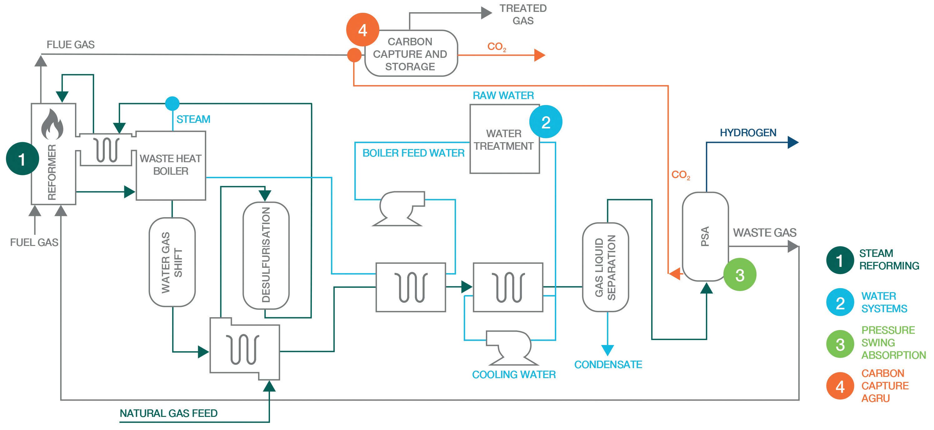
Scope of plant and basis of design
Figure 1 shows the scope of plant covered by McDermott’s validation and engineering development. For the utilities and offsites (other than refrigerant storage), only the aspects directly associated with the liquefaction train were included in the scope/estimate.
The plant was located in northwest Europe with a capacity of 300 tpd of LH2. Construction was based on Asian-built pre-fabricated modules. Seawater cooling via a closed-loop cooling water circuit was assumed.
The feed to the facility could be either blue or green hydrogen. The validation and engineering development focused on the liquefaction block, the relevant utilities, and the required refrigerant storage and transfer facilities. Hydrogen production/pre-treatment facilities and liquefaction interaction with LH2 storage were not addressed. Table 1 shows the Basis of Design (BoD).
A product specification in line with ISO 14687 was selected (for Type II liquid fuels, Grades C and D) with a minimum 95%
para hydrogen. For the initial work, LNG was selected as the methane refrigerant source, as it is readily-available and is of a purity suitable for use within cryogenic systems. Pre-treated pipeline gas may be substituted for LNG if preferred. Nitrogen is, however, emerging as the preferred pre-cooling refrigerant for future developments, as it has several practical advantages and a lower specific power.
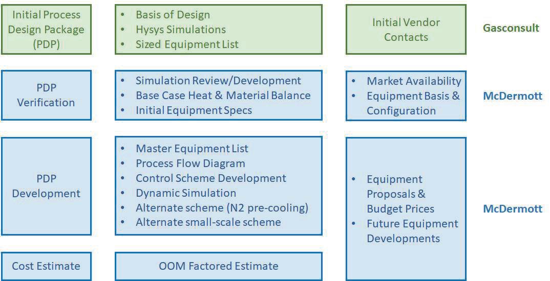
Design verification
Figure 2 indicates Gasconsult’s input into the OHL design, and McDermott’s scope of work for verification and design development.
McDermott assessed the practicality of the pressure and temperature profile; equipment availability and performance; the ortho-to-para hydrogen conversion; inclusion of the heat of reaction; and refrigerant compositions.
Multiple suppliers were contacted to confirm the availability, performance, and level of maturity of the required equipment. Key highlights of the verification process are listed in the next section.
Simulation platform and property package selection
McDermott evaluated Gasconsult’s heat and material balance using AspenTech’s HYSYS process simulation software, and updated the equations of state as follows:
y For the methane precooling section, the Peng Robinson equation of state was used with the Lee Kesler enthalpies.
y The hydrogen liquefaction section was assessed using the RefProp model developed by NIST, which is accepted to be the most accurate available model for hydrogen across the expected operating temperature and pressure range.
Rotating equipment performance
Rotating equipment performance has a significant impact on overall process efficiency. As such, McDermott engaged with multiple rotating machinery suppliers to obtain estimates of machine performance when operating on pure hydrogen, and to identify limitations on aerodynamic performance or material/component selection.
Hydrogen compressor supplier feedback included:
� Centrifugal multi-impeller casing compressors:
� Achievable pressure ratios are currently in the range of 1.3 – 1.5, with potential solutions under development with compression ratios of greater than 1.8 – 2.0.
� Expected polytropic efficiencies in the range of 82 – 85%.
� For reciprocating compressors:
� The largest individual API machine currently operating is 17 MW. Multiple reciprocating machines in parallel are required for a 300 tpd hydrogen liquefaction plant.
Centrifugal compressors were selected for the base case.
Design development
McDermott developed enhanced Process Flow Diagrams (PFDs) and a process control philosophy. A dynamic analysis was performed to confirm OHL’s transient response to turndown/turn-up, equipment trips, and start-up from ambient.
22 Spring 2023 GlobalHydrogenReview.com
Figure 1. Hydrogen liquefaction facility and study scope boundaries.
Property Value Hydrogen feed flow rate 300 tpd Hydrogen feed composition > 99.99 mol% Hydrogen feed pressure 25 bar absolute Hydrogen feed temperature 30 ˚C Seawater temperature 11 ˚C LNG refrigerant storage 2 x 100 m3
Table 1. Basis of Design (BoD)
WE’RE COMMITTED TO A BETTER FUTURE
WE’RE COMMITTED TO A BETTER FUTURE
Optimizing combustion for a greener tomorrow
There has never been a greater need to decarbonize fired equipment, produce cleaner energy sources, and operate in a more environmentally responsible way.
Optimizing combustion for a greener tomorrow
There has never been a greater need to decarbonize fired equipment, produce cleaner energy sources, and operate in a more environmentally responsible way.
Optimized combustion and enhanced predictive analytics are key to reducing plant emissions and ensuring equipment uptime. Designed for safety systems, our Thermox® WDG-V combustion analyzer leads the way, monitoring and controlling combustion with unparalleled precision.
Optimized combustion and enhanced predictive analytics are key to reducing plant emissions and ensuring equipment uptime. Designed for safety systems, our Thermox® WDG-V combustion analyzer leads the way, monitoring and controlling combustion with unparalleled precision.
Setting the industry standard for more than 50 years, AMETEK process analyzers are a solution you can rely on. Let’s decarbonize tomorrow together by ensuring tighter emission control, efficient operations, and enhanced process safety for a greener future.
Setting the industry standard for more than 50 years, AMETEK process analyzers are a solution you can rely on. Let’s decarbonize tomorrow together by ensuring tighter emission control, efficient operations, and enhanced process safety for a greener future.

AMETEKPI.COM/CLEANENERGY
AMETEKPI.COM/CLEANENERGY
The objectives were to confirm:
y That the proposed configuration of equipment and controls enabled robust operation across multiple scenarios.
y A start-up sequence, both from ambient and cold conditions.
y Interactions between rotating equipment and cold boxes during unsteady operating conditions.
The main findings indicated that the:
y Control scheme readily handled flow changes between 50 – 100%.
y Main expander trips do not cause the plant to trip or shutdown, with the control system able to automatically reduce LH2 production to a new steady state.
y Transient temperature excursions are within acceptable limits for the main brazed aluminium exchangers.
y Estimated start-up time from ambient to full production was less than 20 hours.
Design update
The BoD was finalised and the flow scheme (see Figure 3) was updated based on the verification work, feedback from equipment suppliers, and engineering development. The next sections detail the process at length.
Hydrogen feed gas circuit (green)
Hydrogen is supplied to the liquefaction unit at 25 bara and 19°C. The feed gas is combined with recycled hydrogen refrigerant from the H2 Recycle Compressor (CP4) before being
routed to the Precooling Cold Box (PCB) where it is cooled to approximately -150°C using methane refrigerant. Some cooling is also provided by returning low-pressure hydrogen refrigerant streams.
The pre-cooled hydrogen feed is then routed to cryogenic contaminant removal where any residual trace contaminants (hydrocarbons, oxygen, nitrogen, other air gases such as argon, and potentially KOH, depending on the source) from the upstream pre-treatment are removed to (i) protect the ortho-para catalyst (ii) prevent freeze out in the liquefaction section, and (iii) achieve the LH2 specification. Contaminant removal is a regenerative adsorption process with multiple parallel beds, allowing for online regeneration with a slipstream of warmed feed gas.
Pre-cooled hydrogen is then routed into the vacuum-insulated Liquefying Cold Box (LCB) where it is further cooled and makes contact with the ortho-to -para hydrogen conversion catalyst. The enthalpy removed during hydrogen liquefaction, along with the heat of reaction from the ortho -to-para conversion, is absorbed by the hydrogen refrigerant stream. Final cooling is achieved by flashing the liquid hydrogen across a Joule Thompson (JT) valve into separator SP1. The flash gas is routed via CP4 and combined with the feed gas stream; and the liquid hydrogen is routed to storage.
Methane precooling circuit (red)
The process utilises a closed circuit dual-expander methane pre-cooling cycle. The loop contains small amounts of nitrogen, ethane, propane and C4+ from the source LNG. Heavier component build-up may be bled out during start-up and operation.
The methane refrigerant is compressed and circulated by the electrically-driven Methane Refrigerant Compressor (CP1).
The methane stream is then routed through the compressor stages of the Cold and Warm Expander-Compressors (EC2 and EC1) which are direct-coupled and driven by the corresponding expander sections. The compressed methane refrigerant then enters the warm end of the PCB.
A slipstream of cooled methane refrigerant is withdrawn from the PCB and sent to expander EC1 where it is reduced in pressure and then routed back to the PCB to provide warm end cooling. The stream is then routed to CP1 suction.
The split to EC1/2 is flow ratio controlled with the hydrogen feed gas.
The remainder of the methane refrigerant is further cooled in the PCB and routed to expander EC2 where pressure is reduced, resulting in partial liquefaction of the stream, with vapour/liquids separation in SP2. The cold vapour is routed back to the PCB and the liquid is flashed to near-ambient pressure. The liquid phase is routed back to the PCB where it is vaporised to provide cold end refrigeration. The resulting vapour stream is routed to the Methane Recycle Compressor
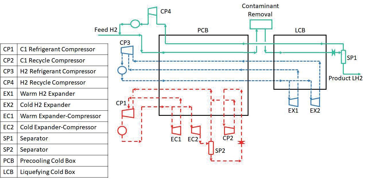
24 Spring 2023 GlobalHydrogenReview.com
Figure 2. Work scope and split.
Figure 3. Base flow scheme.
(CP2) from which it rejoins the methane refrigerant stream from SP2 before being compressed in CP1 and recycled.

Hydrogen refrigerant circuit (blue)
The hydrogen refrigerant cycle operates as a closed circuit with recycled hydrogen compressed and circulated by the electrically-driven H2 Refrigerant Compressor (CP3). CP3 has two feeds that float on the Warm and Cold H2 Expander (EX1 and EX2) outlet pressures. The hydrogen stream is then routed to the warm end of the PCB where it is cooled against the methane refrigerant.
The pre-cooled hydrogen refrigerant stream is then split, with approximately half routed to the LCB and half routed to EX1. The warm expander duty is let down across three expansion stages to provide the first section cooling for the LCB.
The remaining hydrogen refrigerant is further cooled before being reduced in pressure across EX2 and providing the final level of cooling for the LCB.

The hydrogen refrigerant returns through the LCB and PCB to CP3.

Summary of the study’s outcomes
The verification and engineering development work confirmed that Gasconsult’s OHL process has the capability to achieve an overall performance of approximately 6.8 – 7.1 kWh/kg LH2 under the BoD conditions for a 300 tpd LH2 capacity. This represents a power demand reduction of 25 – 40% relative to current operating practice. The overall CAPEX for the 300 tpd facility is estimated to be US$500 million.
Alternative LH2 technologies that are being developed may have a dependence on high cost and scarce refrigerants such as helium and neon. They can also have more complex pre-cooling, using mixed refrigerants that have high refrigerant infrastructure costs to store and blend a range of liquid hydrocarbons. Operation can also be more complex, as mixed refrigerant processes require regular composition adjustment to run at their design point.
Further developments
Following completion of the study, development of the OHL technology has continued.


As an alternative, nitrogen replaces methane (LNG) as the pre-cooling refrigerant. This has practical and operational benefits. All LH2 plants need nitrogen for purging, and the additional consumption of nitrogen required for the OHL process is extremely low, essentially to compensate for leakage losses.
A further benefit of nitrogen pre-cooling is that there are fewer hydrogen expanders required. The configuration of the final cooling/liquefaction was also updated, resulting in a much-reduced installed power of the Hydrogen Recycle Compressor CP4. Overall, the expected kWh/kg LH2 is reduced by 5%.
In a further development, a two-stage pre-cooling arrangement may reduce the power requirement by a further 5%, prospectively reducing the expected specific power to 6.2 – 6.5 kWh/kg under the BoD design conditions (which is typical for a northwestern European coastal site).
Valves Qualified With 99.9% Hydrogen QUALIFIED WITH 99.9% HYDROGEN +44 (0)1565 632 636 | sales@valves.co.uk | www.valves.co.uk Oliver Valves Ltd Parkgate Industrial Estate, Knutsford, Cheshire, WA16 8DX, United Kingdom For more information, contact your local Oliver Valves supplier or call: +44 (0)1565 632 636 Hydrogen qualified valves for topside, subsea, and pipeline applications, endurance tested to over 400 Cycles with ZERO Leakage. Also available are 10/14/20mm full bore gaseous fuel station ball valves.
Increasing the efficiency of both new and existing steam methane reformers (SMRs) is an essential consideration for decarbonising operations. Tim Tallon, AMETEK Process Instruments, and James Cross, AMETEK Land, discuss two ways in which this can be done.
Optimising combustion and ensuring tube integrity in steam methane reformers (SMRs) can help to maximise efficiency and safety, and play an important role in the global movement towards decarbonisation. Increasingly, governments and corporations around the world are evaluating their role in protecting the climate by reducing greenhouse gas (GHG) emissions –particularly carbon dioxide (CO2).
Nevertheless, combustion – one of the main sources of CO2 emissions – will remain essential for power and heat across many industries. The steel, cement and chemical industries, for example, are especially challenging to decarbonise, as are mobility solutions including ships, airplanes and automotive vehicles. Recognising that combustion processes will remain important in our future, large-scale decarbonisation initiatives have developed a number of solutions.

For example, carbon capture methods allow carbon emissions to be removed from the flue gas emissions
generated by combustion. Alternative methods of heat production are also being investigated. Electrification is just one way to generate heat in place of combustion, though this is not suitable where very high temperatures are required. Additionally, hydrogen fuels can generate heat without creating CO2 emissions.
Much of the industrial energy transition is focused on migrating to hydrogen fuels and their production, so there is a huge investment in new hydrogen infrastructure. Hydrogen has been positioned as the low/zero-carbon fuel of the future, driving this transition, and partnerships for blue hydrogen production (where CO2 is captured and stored) and green hydrogen production (where there is a net zero emission of CO2) have brought down costs.
Throughout this transition, SMRs provide the essential backbone of modern day hydrogen production, manufacturing more than 95% of the world’s hydrogen. However, much of this installed base is looking to reduce its CO2 footprint and optimise
its processes for near-term emission targets – with safety in mind.
Increasing the efficiency of both new and existing SMRs is now an essential consideration in decarbonisation. This article will focus particularly on existing assets, looking at ways to increase efficiency, along with the impact on flexibility and safety.
Existing SMRs have the opportunity to achieve efficiency gains to safely decarbonise. One way to accomplish this is by lowering oxygen levels to reduce emissions, though this does create safety margin risks. While carbon capture systems offer a long-term emission reduction strategy, efficiency gain by the SMR can reduce near-term emissions within the operator’s control.
SMR combustion safety and efficiency
SMRs are widely used in hydrocarbon processing applications. The process requires combustion to heat the reaction tubes,
converting methane and steam – via a catalyst – into hydrogen. Combustion is critical to delivering the temperatures required. A range of burner configurations exist, including down-fired, side-fired, terrace-fired, top-fired, and bottom-fired, but the same principles apply in each case. For further elaboration, this article will highlight two key principles for SMR combustion safety and efficiency: combustion optimisation, and tube wall temperature (TWT) monitoring.
Combustion optimisation
Based on the ‘fire triangle’, combustion requires three things: oxygen (usually from the air), fuel, and heat – remove any one of these, and you cannot create a flame. Any combustion process will be incomplete to some extent, and this creates combustibles (typically in the form of carbon monoxide [CO] and hydrogen). Incomplete combustion may be a result of poor mixing of the air and fuel, changing load conditions, malfunctioning burners, or variable fuels.

27
When it comes to operating fired processes, the perfect combustion reaction is known as stoichiometric combustion. This is when the air-fuel mixture is at the ideal level for the fuel and oxygen to react and create CO2 and water with perfect efficiency. In SMR applications, it allows the maximum useful heat to be transferred to the tubes.
In stoichiometric combustion, there is no excess oxygen to be measured, as all of the available oxygen is fully consumed in the reaction. However, in reality, operations are usually performed in conditions of slight excess oxygen in the flue gas – typically 2% – as a safety margin. This inevitably leads to the generation of low-level combustibles.
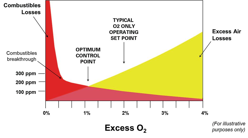
On the other hand, oxygen-deficient (or fuel-rich) conditions produce high levels of combustibles and can be very dangerous, as well as being much less efficient. Therefore, measuring excess oxygen, by itself, becomes very important in ensuring a safe operating set point for combustion.

However, when it comes to optimising combustion, additional information is needed. If excess oxygen levels are too high, more fuel is also consumed, causing greater levels of CO2 and nitrogen oxides (NOx) emissions.
This is where measuring combustibles provides a critical secondary reference point for optimisation. As noted in Figure 1, combustibles are very high when there is little excess oxygen but eventually stabilise after a certain ‘breakthrough’ point. Above the breakthrough point, combustibles are too high for safe operating conditions and pose a safety concern. However, below the breakthrough point, the combustibles gradually decrease with added amounts of excess oxygen.
By measuring excess oxygen and combustibles together, with a combustion analyser, operators can lower their excess oxygen levels while also monitoring to ensure that they are safely below the combustibles breakthrough point. The result is optimised combustion: a lower, more optimal excess oxygen set point that drives lower fuel consumption at the burner and fewer emissions at the stack.
TWT and the effect on tube lifespan
As mentioned, when excess oxygen in the combustion reaction is reduced, the level of combustibles increases. However, this also increases the TWT in the SMRs, so lowering the excess oxygen too much can result in damage to the tubes themselves. An accurate measurement of TWT is very important for optimised operation, safety, and maximising infrastructure assets.
Typically, the operating window for TWTs is between 300 – 1300°C (572 – 2372°F). Exceeding this temperature is above the design limit of the tube and will shorten its lifespan. Falling below this range, on the other hand, will lead to a loss of production.
Measurement accuracy – through proper data correction – is key: reading inaccurately high can lead to high methane slip (inside of the tubes from the SMR reaction), as the process is not running at the expected temperature and the catalytic reaction is lower than it should be. This will increase unwanted emissions. There will also be a margin loss, via low plant load/yield, as the methane is not used optimally in the reaction. An inaccurate high temperature reading can also lead operators to chase false alarms, investing time and resources into fixing issues which do not exist.
Conversely, an inaccurate measurement that is lower than the real temperature will create safety and reliability issues, as the tubes may become damaged or ruptured. This loss of reliability will damage margins again. If the measurement is off by 20 – 30°C, this can affect tube lifespan by as much as 10 years.
Carbon formation in SMR tubes
One of the major causes of overheating tubes – and ultimately inefficiency – is carbon. Carbon formation on the inside of the tube can be caused by a number of factors, including a low steam-to-carbon ratio (i.e. a rich process gas); heavy hydrocarbons in the feedstock (which occurs more often as gas wells approach the end of their useful life); issues with the catalyst or loading; insufficient purging of residual hydrocarbons prior to restart; or a complete loss of steam. Additionally, when catalyst activity drops, the tube inside wall and process gas temperature both increase, so the carbon formation rate exceeds the carbon gasification rate.
Carbon formation inside the tube is normally visible as hot bands on the reformer tubes. Once carbon is formed, it reduces the inside tube wall heat transfer coefficient and the inter-pellet heat transfer coefficient.
As the active nickel sites are covered by carbon, reducing their temperature, catalyst activity is reduced. Carbon formation also leads to an increase in resistance to flow through the affected tube – a pressure drop. This decreases the heat sink available and further increases the TWT.
28 Spring 2023 GlobalHydrogenReview.com
Figure 1. Overlay of the efficiency losses caused by excess oxygen and by combustibles, which reveal an optimal combustion control point.
Figure 2. The Cyclops C100L and C390L are a single point handheld pyrometer used to measure TWTs across a range of fired heaters.
As the leading innovator, we continue to supply our customers with the technology, methods, and consultancy to make the best integrity management decisions for their assets. No matter what the future holds, renewable hydrogen as a flexible energy carrier plays a vital role in moving the industry further; we want to make sure you are ready.

Fit for the Future. Ready for Hydrogen.
www.rosen-group.com
When a single tube overheats, it can lead to a runaway reaction where its higher temperature radiates onto nearby tubes, often leading to batches or banks of multiple overheated tubes. To counter this, producers will reduce firing around these tubes but, in order to maintain productivity, will increase the general level of firing, resulting in reduced overall efficiency and a higher risk of overheating tubes elsewhere in the SMR. To remove the carbon formed on the interior of the tubes, producers will reduce temperatures and steam the tubes. This carbon gasification process produces significant volumes of CO2
Reducing severity of coking and hot bands can therefore have a significant impact on general efficiency.
Optimising TWTs
The cost of replacing damaged tubes is significant. One customer reported a 12-fold return on investment (ROI) when overheated tubes were identified. The cost to replace the tubes would have been US$80 000, along with US$300 000 lost opportunity avoidance (hydrogen available for hydrotreaters).
Additionally, 22% of equipment failures in the ammonia industry causing shutdowns have been identified as involving the primary syngas reformer, and more than half of those failures involve TWT excursions.
By optimising TWT, hydrogen producers have reported a 2% increase in production, all while continuing to operate under safe conditions within their integrity operating window.
For spot temperature measurements of the tube wall, a handheld pyrometer can be used effectively, as shown in Figure 2. This is an infrared pyrometry-based instrument operating at multiple wavelengths, and is normally used manually, though values can also be recorded wirelessly.
The small spot size means that a lot of the furnace can be covered with a single instrument, with readings typically taken at an emissivity of 1 and adjusted during analysis to find the corrected temperature.
The peep-door cooling effect must be understood prior to measurements being taken with a pyrometer fixed on multiple tubes. It can lead to a huge variety in reported results, from negligible effect to 40˚C differences and 45 minute recovery times, depending on furnace and ambient conditions.
To calculate the emissivity of the tube, a gold cup reference measurement can be used. This 9 ft long, 50 lb water-cooled
probe is an excellent tool to understand the reformer and effects of emissivity, background, and sight path.
Another instrument which can form part of the suite of tools for understanding how an SMR is operating is a portable thermal imager, developed to enable surveys and inspections while drawing on the wide-angle field of view benefits of borescope technology.
The camera uses an air-cooled lens to keep the tip temperature below 50˚C, typically, using up to 300 l/min of air, and a range of lengths, lenses, wavelengths, and accessory options are available to support specific applications. For example, a narrower lens provides more resolution on tubes further away from the peep door, while a wider-angle lens allows more tubes to be viewed in a single scene.
Once the data has been collected, operators and inspectors can use corrected data from thermal images – supported by gold cup and portable pyrometer information – to create a thermal profile of the fired heater. This helps to identify the hottest and coldest tubes, allowing operators to improve balance and efficiency, and reduce the risk of tube failure. It can also support monitoring for air leaks in the tubes.

Fixed thermal imaging cameras can be installed on the furnaces – with water or air-cooling – to provide continuous, full or partial coverage of the reformer. The number of cameras required depends on the SMR design. Data from these cameras allows real-time TWT monitoring and alarming, for continuous optimisation.
Software automation
The question for both decarbonisation and digitalisation applications is how to turn thermal imaging streams and billions of temperature data points into a cohesive automated system that optimises furnace monitoring and control, as reported in Figure 3.
Customers demand application-specific solutions, and the industry is ready for advanced software with automation and artificial intelligence (AI) that can automatically thermally map reformers in real-time, and provide advanced warning of temperature-related phenomena. The challenges going forward include implementing cloud-based pattern analysis and recognition, closed-loop control, and real-time correction of models and simulations.
By effectively utilising the data from SMR measurements, the overall efficiency of furnaces can be significantly improved, helping blue hydrogen to compete with the reducing price of some of the hydrogen produced by other methods.
Conclusion
Combustion remains important to industry, despite global efforts to reduce carbon emissions. Hydrogen offers a low-emission fuel alternative, and much of its production is driven by existing SMR facilities.
Combustion optimisation in furnaces reduces excess oxygen levels in the flue gas, lowering fuel consumption and reducing CO2 emissions, while also monitoring for safety. Accurate thermal imaging of TWTs helps to ensure that there are no hot spots in the tubes, further supporting uptime and safety.
Overall, a combined understanding of flue gas analysis and TWT temperature data allows SMR operators to improve balance, efficiency, and combustion safety.
30 Spring 2023 GlobalHydrogenReview.com
Figure 3. Automated monitoring systems can identify temperature anomalies around burners, and alert operators so that corrective action can be taken.
Spurred on by the COVID-19 pandemic and increasing pressure on governments and businesses to achieve net zero ambitions, hydrogen is set to be a key part of a clean energy future. A 2022 DNV report highlights that half of senior energy professionals are expecting it to represent a significant proportion of the energy mix by 2030, and 42% declared their intent to invest in the field.1
DNV identified six primary barriers to the scale-up of the future hydrogen society, the most important being infrastructure; production processes; and safety and hazards (others being investments, demand, and policy, regulations and standards). Proving the safety of hydrogen across the whole energy value chain will be crucial for its uptake as an energy carrier. DNV has been working to set and check requirements for safe and reliable design, construction and use of hydrogen; deliver risk studies and develop and support regulatory documentation with industry; and advise governments globally.
DNV’s latest ‘Global Energy Transition Outlook’ report found that hydrogen will scale up in the manufacturing sector from the early 2030s in the leading regions of China and Europe. Hydrogen derivatives such as ammonia, e-methanol and other e-fuels will

also start scaling up in the late 2030s, and include heavy-duty road transport.
Although DNV estimates that maritime vessels powered by pure hydrogen and ammonia could be on the water within eight years – and currently there are three hydrogen vessels on order – the lack of design guidance is complicating the building process of such vessels.2
There will be a more limited uptake of pure hydrogen as a fuel in heavy, long-distance trucking, and in the heating of buildings in areas with existing gas distribution networks, and almost zero use in passenger vehicles. The number of hydrogen initiatives in hard-to-abate sectors is growing rapidly, but few have reached final investment decision (FID).3
Driving hydrogen adoption in ageing assets
The properties of hydrogen require consideration across its value chain based on application and context, in order to determine the best source, state and derivative for each infrastructure and appliance. While experience of working with natural gas or petrol vapours can be useful for starting operations with hydrogen, there
31
Jørg Aarnes, DNV, Norway, describes methods to ensure safety during the hydrogen revolution.
are significant differences in crucial aspects such as dispersion, flammability and ignition conditions that require specific safety adaptations. For instance, hydrogen ignites with very low energy and has a wide flammability range, relative to familiar alternatives. It is also colourless, tasteless and odourless. With these characteristics, current safety philosophies require the experienced use of advanced tools to identify, assess and manage risks.
Producers must also tackle the safety challenges associated with electrolyser and blending unit installations, which pose possible internal explosion and leakage hazards, in order to ensure safe operation.
On the upstream supply chain side, testing and modelling still requires fine-tuning to consider hydrogen’s unique properties, and subsequently adapt handling, storage and bunkering safety aspects accordingly.
While DNV forecasts that hydrogen for building heating and cooking will not scale globally, it will see early uptake in some regions that already have extensive gas infrastructure. For it to gain broad adoption in domestic settings, the public, including millions of potential end users, need reassurance that hydrogen will be safe in all contexts. In order to achieve this, industry and regulators must establish robust safety standards for each specific use case, just as they do for other potentially-dangerous substances.
Gas distributors such as Northern Gas Networks (NGN) and Cadent are advocating for the UK government to support hydrogen in the home as part of the country’s net zero strategy, and to subsequently make the policy decision that hydrogen can be used as a low-carbon fuel for heat. NGN and Cadent were recently given the green light by government and energy regulator, Ofgem, to develop its proposal that could see Redcar in Yorkshire, or Whitby in Cheshire, become the UK’s first hydrogen village. The plan would see around 2000 properties in the town centre and surrounding areas switch from natural gas to clean-burning hydrogen.4
In clear steps to manage the safety of hydrogen as an energy carrier, relevant stakeholders are undertaking pilot projects and employing a risk-based approach using safety modelling and experiments. Various energy companies are following similar strategies, conducting research and development (R&D) into the safety, efficacy and viability of hydrogen applications.
Ageing steel pipelines in the UK distribution network are already being replaced with polyethylene pipes for safety reasons, and so are well positioned for repurposing with hydrogen. Once installed, they have a lifespan of around 80 – 100 years, which is ideally suited for the distribution network close to people’s homes. However, when looking at upstream applications with high-pressure tiers, metallic pipes are commonly used. This is where greater challenges lie, and more information is required. It is also important to
consider not just pipelines, but other parts of the system such as valves, compressors, and measurement equipment.
In Hungary, work is also underway to assess how existing natural gas pipelines can be repurposed for hydrogen transportation. FGSZ Ltd – the owner and operator of the Hungarian high-pressure transmission natural gas pipeline system servicing gas distribution companies, power plants, and large industrial consumers – commissioned DNV to assess the suitability for partial to full hydrogen transport of one of its pipelines. The intention of the project is to evaluate the suitability of FGSZ’s DN600 system, which consists of a DN600 pipeline and valve station for hydrogen transportation. FGSZ has set up different scenarios to assess the implications of exchanging natural gas with up to 100% gaseous hydrogen, which will be key to developing a large-scale hydrogen economy.
DNV is supporting the operator in navigating the risks and opportunities of the energy transition, utilising the company’s experts in pipeline material, safety, integrity and pipeline inspection.

Practical testing in domestic settings
DNV’s Spadeadam research and testing facility is supporting the scaling up of hydrogen, with its HyStreet infrastructure conducting necessary safety tests as part of the H21 project led by NGN and the UK government’s Hy4Heat programme (see Figure 1). The premises is home to three ordinary-looking houses which are playing a central role in multi-million-dollar tests. DNV has specially designed and built the row of buildings, called ‘HyStreet’, to establish whether it is technically possible, safe and convenient to replace natural gas with hydrogen in residential and commercial buildings and gas appliances. Experts at Spadeadam are comparing what happens if hydrogen and natural gas leak from networks or in buildings, and the relative risk and possible consequences of them igniting.
The testing assesses how hydrogen leaking outside the houses can move differently in varying soils, before breaking the surface. Hydrogen from a bank of cylinders reaches the houses through 27 different service pipelines chosen to represent the types and diameters of distribution pipes in the UK. 18 potential release points in the mains can be opened and closed. The experiments are also assessing how leaking hydrogen from the ring main – a domestic electrical supply in which outlet sockets are connected to the mains supply through a ring circuit – can track in different ways through street furniture such as kiosks, and from other ducts that may have been installed for utilities. A ring main is an electrical wiring technique in which sockets and the distribution point are connected in a ring.
The testing programme also investigates what happens if the leak is in the home itself. Numerous release points within the buildings can be used to simulate leaks of hydrogen within the properties. The houses are representative of UK housing stock, but with individual nuances to give as wide a representation as possible of different house types across the UK. Variations include: a suspended wood floor, which is typical in traditional UK housebuilding; a solid concrete floor, found in some modern homes; a basement, not uncommon among older properties; and an attached garage.
To further simulate a typical home, the kitchens are fitted with familiar appliances and services such as natural gas, electricity and water, and connected to a drainage system. Each house is also fitted with some 75 sensors to detect and measure hydrogen
32 Spring 2023 GlobalHydrogenReview.com
Figure 1. DNV’s Spadeadam research and testing facility is supporting the scaling up of hydrogen, with its HyStreet infrastructure.
concentrations at various heights in every room. In the transition from gas to hydrogen, ensuring that homes have infrastructure ready for the switchover is also important. Currently, appliances such as gas boilers are not able to function with 100% hydrogen, and while a natural turnover will take place as ageing appliances are replaced, manufacturers will need to support the transitions with more hydrogen-ready boilers.
DNV is also working with National Grid to address some of these issues by taking decommissioned transmission assets from the National Transmission System and building a test loop at Spadeadam. FutureGrid is a very ambitious project and will run hydrogen and natural gas blends as well as 100% hydrogen through them to verify compatibility and safety (see Figure 2).
Standardising hydrogen safety
As hydrogen becomes more widely utilised in the evolving energy mix, standardising its application will also be important to ensure the safety of its use. In 2022, DNV launched a new JIP to enhance the standardisation for reliable, safe and cost-efficient hydrogen production systems that use renewable energy-powered electrolysis to produce green hydrogen.5 Electrolysers are hydrogen-producing devices, splitting water into hydrogen and oxygen using electricity in a chemical process known as electrolysis.
In order to grow confidence in the market, electrolysers require further standardisation. This will capture and reduce uncertainties and risks in the increasing industrialisation of hydrogen production, and in hard-to-abate sectors such as aviation, maritime, and long-haul trucking.
Similarly, DNV is leading three parallel JIPs to develop the existing KFX software, which simulates gas dispersion, fire and explosions to increase safety in the deployment of energy transition solutions. The KFX computational fluid dynamics (CFD) software simulates what happens to liquids, vapour clouds and potential dry ice formation in the event of accidents. The simulations are used as the basis for design of installations, and to mitigate consequences. In the event of an accidental release, there are widely-varying scenarios depending on the properties of the gases or liquids involved. The first JIP is a partnership between Equinor, TotalEnergies and DNV, and focuses on carbon dioxide (CO2).
The research concentrates on the consequences of accidental release, depending on surrounding environmental conditions such as terrain and wind, combined with dry ice formation and its impact on dispersion. The second JIP includes Equinor and DNV, focusing on hydrogen and the consequences of low storage temperatures, dispersion, fires and explosivity.
KFX CFD software has been developed for more than 25 years by DNV, in collaboration with Equinor, TotalEnergies, ConocoPhillips, Eni, Gassco, GRT GAZ, and other energy companies, as well as the Research Council of Norway.
Similarly, DNV has owned the testing laboratory in the Netherlands since 2012, and the facility is playing a leading role in driving green hydrogen adoption. The research premises aim to determine what adjustments are needed for natural gas pipelines and associated equipment such as valves, membranes, and pressure gauges, in order to support the transport of green hydrogen.
In Asia, DNV and Keppel Offshore & Marine (Keppel O&M) have been collaborating to explore safe implementation of potential new technologies, working jointly with relevant governmental agencies to promote the introduction of hydrogen as an energy source in the
Singapore market to support the country’s decarbonisation goals. Safety requirements for hydrogen as an energy source is a key area.
DNV is currently supporting The Oil and Gas Climate Initiative (OGCI) to assess the potential safety-related barriers to wide-scale adoption of hydrogen in the transportation sector, working closely with the CEO-led organisation to study safety aspects, challenges and requirements of upscaling hydrogen in the sector.
DNV has also been involved in investigating the safe transportation of hydrogen at sea. A consortium of 26 leading companies and associations, led by DNV, launched the ‘Handbook for Hydrogen-fuelled Vessels’ to address the uncertainties surrounding hydrogen as a shipping fuel. The MarHySafe joint development project (JDP) aims to create a knowledge base for safe hydrogen operations in shipping.
Driving a hydrogen future
Looking to the future, financial leadership and commercial readiness are key challenges facing the scaling up of the hydrogen industry. Greater collaboration is also vital to ensure that safety concerns are addressed. Upskilling and competence development will be very important requirements for the hydrogen industry. DNV is delivering training courses, from leadership to operational level, to ensure that the future workforce has the knowledge and skills to safely develop future hydrogen networks and services.
Hydrogen will remain a critical element of the energy transition and while significant progress has been made, there is still great work to be carried out in order to support the transition of gas networks to hydrogen, for example, to ensure that countries such as the UK reach their net zero destination by 2050.
References
1. ‘The Power of Optimism: Managing scale and complexity as the energy transition accelerates’, DNV, https://www.dnv.com/ Publications/the-power-of-optimism-managing-scale-and-complexityas-the-energy-transition-accelerates-219562
2. ‘DNV rules out pure hydrogen as a future long-distance shipping fuel’, Recharge, (8 September 2022), https://www.rechargenews.com/ energy-transition/dnv-rules-out-pure-hydrogen-as-a-future-longdistance-shipping-fuel/2-1-1292932
3. ‘Energy Transition Outlook 2022’, DNV, https://www.dnv.com/energytransition-outlook/download.html
4. ‘Go-ahead given to draw up plans for hydrogen village as ‘world first’ Teesside experiment concludes’, Teesside Live, (31 October 2022), https://www.gazettelive.co.uk/news/teesside-news/redcar-hydrogenvillage-plans-update-25400451
5. ‘DNV launches new Joint Industry Project to ensure reliable, safe and cost-efficient hydrogen production systems using electrolysers for the growth of green hydrogen’, DNV, (10 February 2022), https://www.dnv.com/news/dnv-launches-new-joint-industry-projectto-ensure-reliable-safe-and-cost-efficient-hydrogen-productionsystems-using-electrolysers-for-the-growth-of-green-hydrogen-218610
Spring 2023 33 GlobalHydrogenReview.com
Figure 2. The development of the FutureGrid facility.
Today’s energy grid and the available pipeline network, in particular, will play a major role in the transition to net zero, connecting supply and demand. No pipeline is the same, and owners, operators and integrity engineers need to ensure that they understand and manage the integrity of the asset. Traceable, verifiable and complete manufacturing and construction records, as well as a thorough understanding of the anomaly population in the asset, are fundamental parts of integrity management.
State-of-the-art inspection technologies support the pipeline industry in managing threats such as geometry, metal loss, material properties and cracking, with a variety of solutions. This service portfolio will also be a key component when it comes to repurposing pipelines from natural gas to hydrogen under existing regulations and guidelines, including ASME B31.12.
Energy systems
The current carbon-based energy system is undergoing profound changes, driven by increased concerns over the longevity and security of fossil energy. Countries around the world are looking for ways to transform their energy systems. Initiatives such as the European Hydrogen Backbone illustrate and summarise the efforts to transform the current European energy systems, with the aim of ensuring the future security of energy supply, and lowering greenhouse gas emissions.1 Pipelines play a major role in the transformation of the energy system because of their ability to safely transport energy over long distances and act as storage at the same time. Compared to electrical power lines, pipelines can carry more energy and are already (or easily can be) directly connected to existing storage infrastructure, such as caverns. This integrated

34
Jens Voss, ROSEN Group, introduces the diagnostic solutions that are available for supporting future fuel pipelines.
set-up enables countries such as Germany to integrate imported energy via pipeline from sources with lower energy production costs. Especially with regard to international climate protection goals, the high energy density, and the established, partly global transport infrastructure (e.g. pipeline connections from Scandinavia or the Mediterranean, and new terminals to import LNG from overseas), it can be assumed that a global market for carbon dioxide (CO2)-neutral gases (and fuels) will develop.2 A transformed energy landscape with significantly lower emissions will be based on the sector-coupling principle, providing greater flexibility to the energy system so that decarbonisation can be achieved in a more cost-effective way.3
Figure 1 illustrates the different sources of energy (left) and highlights the various forms of energy that could be present in a pipeline.
With more focus on pipelines in the energy sector, it can be seen that the energy is transported via different carriers, such as hydrogen, ammonia, oxygen, biomethane or CO2 1 These carriers are called future fuels. Purpose-built pipeline networks transporting these fuels are already in use today – but in a significantly smaller volume than will be needed going forward.1 Low-carbon gases and their associated products can reliably and efficiently be transported, stored and distributed in existing and newly-built global pipeline network. Pipelines will also be used to assist carbon capture, utilisation and storage (CCUS) projects by transporting CO2 safely from emission locations to permanent storage or end use locations. The transportation of these fuels through pipelines will require the consideration of both general and specific integrity threats and damage mechanisms in order to ensure safe and efficient operation.

35
These challenges can only be managed with a comprehensive integrity management system.4 The transformation of the energy system will encompass the repurposing of existing infrastructure and the building of new pipelines according to latest design standards.5
Threats to manage in future fuel pipelines
If future fuels (or indeed any fuels) are to be transported through pipelines, pipeline integrity must be assured to allow for safe long-term operation. This concept of integrity management is not new to pipeline operators, as demonstrated by the long, proud and safe history of the existing pipeline network. Nevertheless, it is worth revisiting in the context of future fuels. In essence, the key points of interest for any pipeline integrity management system are:
y Pipeline condition: what are the time-dependent threats? Which types of defects should I tackle? Where? How severe?
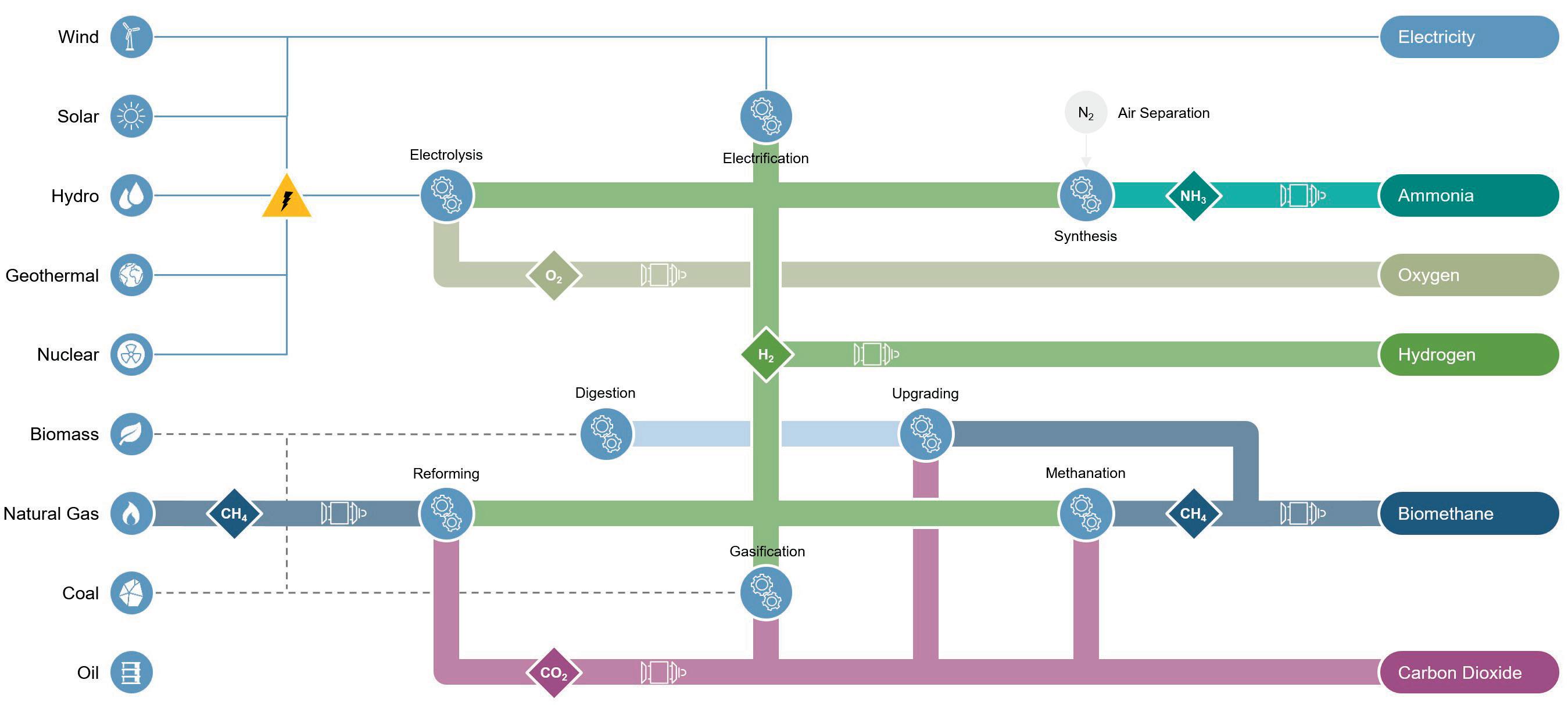
y Integrity remaining life: how safe are my pipeline operations? For how long?
y Consequences: what are the consequences of loss of containment?
y Management: can I safely manage pipeline operations?
The introduction of different fluids into pipelines will not change how integrity management should be tackled, but it will introduce its own specificities and challenges. It is therefore necessary to consider each fluid in turn, identify the relevant threats, and outline how these can be monitored, inspected and managed. The management of these threats is best understood in the context of an integrity framework.4,6 This is summarised in Table 1, which also provides an overview of the principal threats of interest.
The introduction of future fuels into a pipeline system will affect the assets. Assessment solutions to reliably detect, identify and size these threats during repurposing activities, as well as in future fuels operations, are critical for the safety and reliability of the asset from an economic perspective. A best practice in the energy industry is a full suite of assessment methods and measurement capabilities that include in-line inspection (ILI) solutions, pressure testing for pipelines, and direct assessments.
Integrity assessment methods
Regulators and industry groups are collaboratively working on rules and standards to safely transform oil and gas pipelines. Repurposing activities will be the focus of the industry for a large number of existing pipelines of different ages, diameters, material characteristics, and associated anomaly populations. Standards such as ASME B31.12 support these activities, and demand an in-depth understanding of the asset itself.
Construction records, material certifications, and testing for future fuel operations, as well as updated threat assessments, are only a fraction of the efforts that need to be executed for a successful and cost-effective transformation process.5
At the core of these activities are pipeline integrity assessment methods, which can be split into four different categories:
y ILI.
y Pressure testing.
y Direct assessment (DA).
y Alternative methods.
ILI is a non-destructive inspection technique that can be used for pipeline integrity assessments. The type of ILI survey performed is dependent on the type of integrity threat that is being assessed.
Pressure testing is a destructive testing technique to detect/eliminate (by failing) the largest defect in the pipeline that can fail due to internal pressure (i.e. pressure-dependent defect) at the time of testing.
DA is a non-destructive assessment technique for classifying pipeline regions with common characteristics (i.e. pre-assessment) that may be experiencing the selected integrity threat (e.g. external corrosion, internal corrosion, or stress-corrosion cracking).
Alternative methods such as inferred condition technologies and data analytics may be used when operational (e.g. pipeline system configuration), technological (e.g. small diameters), and environmental (e.g. water availability and disposal) conditions do not permit the other three main types of pipeline integrity assessment methods.7
ILI technology can be of significant value in repurposing activities, as it is highly utilised in today’s pipeline integrity management. The support of integrity decisions with measurement data has improved over recent decades, and technological developments in other industries (telecommunication, defence, IT, etc.) will further enhance these abilities. ILI tools can be classified by integrity threat type or technology principle; widely used principles are mechanical calipers, magnetics, eddy current, ultrasound and electromagnetic acoustics. Knowing pipeline integrity threats related to hydrogen and other future fuels, it is possible to acknowledge that different kinds of ILI
36 Spring 2023 GlobalHydrogenReview.com
Figure 1. Sector-coupling principle with different forms of energy in pipeline transport.
technologies can support the integrity management of such pipelines. Those ILI technologies could be for the detection of deformations, mapping or corrosion, for example. Technologies could also include those that are particularly applicable to future fuels, such as determination of material properties or detection of cracks and crack-like anomalies in gas pipelines.4
Today’s in-line diagnostic portfolio delivers solutions from simple cleaning applications to high-resolution crack detection services. It is important that all of these applications are also available in future fuel assets. Therefore, ROSEN is creating solutions to adapt its fleet of inspection tools, readying it for future fuels. Initial inspections in smaller-diameter product lines for hydrogen, ammonia and CO2 have already been conducted in the past4, and utilisation of the lessons learned and use of the solutions in larger diameters and for longer inspection lengths are under development.
The inspection tools need to be modified to withstand the environment in future fuels pipelines, which can be very different compared to oil and natural gas. Products such as ammonia, CO2 and hydrogen pose specific challenges for the materials on the inspection tools, and intense upfront testing and understanding of deterioration processes is key for inspection vendors to be able to deliver a high-quality service.
Table 1. Integrity threats in future fuel pipelines
Name of threat Threat
General External corrosion
Feature type
Metal loss
Third-party damages Dents, gouges
Geohazard
Manufacturing/construction (materials and welding)
External enviromentally-assisted cracking (EAC)
Hydrogen Material embrittlement
Bending strain
Crack-like/cracks
Cracks
Low fracture toughness under hydrogen environment
Hydrogen cracking damages Cracks
Additional considerations
CO2 Ductile fracture
Internal corrosion
Hard spots, geometry anomalies, bending strain
Low material toughness
Metal loss
Internal SCC Cracks
Ammonia Internal SCC Cracks
Internal corrosion
Metal loss
Application Technology principles Services
Cleaning Mechanical scrapers, brushes RoClean
Deformation/ movement
Calipers, eddy current, gyroscope RoGeo
Metal loss Magnetic flux leakage, eddy current, ultrasound RoCorr
Material properties Magnetic flux, eddy current RoMat
Cracking Ultrasound, electromagnetic acoustic transducer, eddy current RoCD
Another key aspect of ILI is the ability to gather a high-quality data set under the harsh conditions in pipelines. Solutions such as speed control valves and low-flow/low-pressure set-ups enable a constant flow velocity without speed excursions or tool stops. With the lower density of hydrogen compared to natural gas, these solutions hugely aid success.
The safety regulations for operations of ILI solutions might change with the introduction of more hydrogen into the pipeline networks. Existing ATEX certificates might need to be updated to ensure proper consideration of the lighter hydrogen in onsite safety procedures.
Conclusion
Existing pipeline infrastructure will play a major role in the transformation process of the energy industry. In practice, this means that ageing pipelines must be converted to transport fluids that are very different from those for which they were originally designed. A comprehensive, integrity-led approach is required to maintain safety during this transition.
The service life and compatibility of the ILI tool parts strongly depend on the tool run conditions, the chemical composition of the fluid, and the exposure time. Available solutions are suitable to enable ILI in hydrogen, CO2, ammonia, and other future fuels. The proposed inspection technologies for pipelines
that are transporting future fuels will need to be assessed for each pipeline within the context of an integrity framework; however, it appears likely that high-resolution corrosion services, crack-detection services, and material properties services will be required. ROSEN is conducting work to provide these services in the environment of future fuels.
References
1. VAN ROSSUM, R., JARO, J., LA GUARDIA, G., WANG, A., KUEHNEN, L., and OVERGAAG, M., ‘European Hydrogen Backbone’, (2022).
2. BOTHE, D., JANSSEN, M., VAN DER POEL, S., EICH, T., BONGERS, T., KELLERMANN, J., LUECK, L., CHAN, H., AHLTERT, M., QUINTEROS BORRAS, C. A., CORNEILLE, M., and KUHN, M., ‘Der Wert der Gasinfrastruktur in Deutschland’, Frontier Economics, (2017).
3. ‘Potentials of sector coupling for decarbonisation’, Frontier Economics, (2019).
4. GALLON, N., HUMBERT, M., and TEWES, M., ‘Energy Transition and the impact on pipeline integrity’, Pipeline Technology Journal, (2022).
5. ‘ASME Code for Pressure Piping, B31.12: Hydrogen Piping and Pipelines’, ASME, (2019).
6. GALLON, N., and VAN ELTEREN, R., ‘Existing Pipeline Materials and the Transition to Hydrogen’, (2021).
7. MORA, R., HOPKINS, P., COTE, E. and SHIE, T., ‘Pipeline Integrity Management - A Practical Approach’, ASME, (2016).
Bibliography
For a full bibliography, please visit:https://www.globalhydrogenreview. com/special-reports/01032023/assisting-transformation--bibliography/
Spring 2023 37 GlobalHydrogenReview.com
Table 2. Applications and technologies

38
The success of the energy transition hinges on creating sustainable, reliable and affordable energy supply for all. Achieving this will require a diverse and balanced energy ecosystem with contributions from both natural gas and renewables. Hydrogen will also play a critical role in opening up new decarbonisation pathways, particularly for industries that have been deemed hard-to-abate.
As the world’s largest exporter of LNG, and a hub for renewable energy, Australia is in a good position to become a global leader in the clean hydrogen market. In 2021, 29% of the country’s total electricity generation was from renewable energy sources, including solar (12%), wind (10%) and hydropower (6%).1 More than 80 GWe of green hydrogen production projects have already been announced in the country.2 Initiatives to increase blue hydrogen capacity via coal regasification and steam methane reforming of natural gas, in combination with carbon capture, are also gaining traction.

While continued production growth will be key to establishing a robust hydrogen economy in Australia, a reliable and efficient transport network is also needed to enable widespread domestic use, and for exporting hydrogen to demand centres in Asia-Pacific and other regions of the globe.
Among all modes of transport, pipelines remain the most efficient option for moving large volumes of hydrogen. Several thousand kilometres of pure hydrogen pipelines are in operation across the globe today. Given the high cost and regulatory hurdles associated with building these pipelines, many stakeholders across both public and private industry have begun asking whether it is possible to use existing natural gas infrastructure to move hydrogen.
This article will provide answers to these questions by discussing what (if any) modifications are required to prepare legacy compression stations for partial or even 100% hydrogen operation.
39
Brian Mason and Chirag Sehgal, Siemens Energy, discuss how Australia is preparing for the hydrogen economy by way of retrofitting existing compression and transportation infrastructure.
Transporting hydrogen vs natural gas
Although the calorific value (CV) of natural gas is roughly three times higher than that of hydrogen, the energy transport density of identical pipelines carrying the two would be relatively similar. This is largely due to the much lower density of hydrogen, which allows for higher velocity and flow rates. In long-distance transmission lines, which typically operate at high pressures, energy flow with high contents of hydrogen hardly decreases in comparison to pure natural gas operation.

While blending hydrogen with natural gas does not materially affect the amount of energy that can be transported through the pipeline, it does have implications when it comes to compressibility – particularly when using centrifugal (i.e. turbo) compressors, which utilise high-speed impellers to convert rotational/kinetic energy into pressure.
The gas kinetic energy is a direct function of its velocity and molecular weight. Hydrogen’s molecular weight is roughly 1/8th of that of natural gas, which means a higher velocity is required to achieve the same pressure. This can be done in one of two ways. The first is by increasing impeller tip speed and/or expanding the diameter of the impeller. The limiting factor here is the mechanical strength limits of the impeller materials. The second is by incorporating additional compressor stages, which increases the overall footprint and cost of the package.
Significant advancements by original equipment manufacturers (OEMs) have been made in recent years, which
have enabled turbocompressors to better handle hydrogen. Siemens Energy’s STC-SVm platform, for example, is specifically designed for high rotational speeds and allows for a smaller and lighter compressor unit with fewer stages than legacy machines in hydrogen service.
Many existing turbocompressors in pipeline applications today can be operated with a low content of hydrogen in the gas stream. However, as the percentage of hydrogen by volume increases, modifications to the machine are necessary to ensure safe and efficient operation.
Typically, for admixtures with less than 10% hydrogen by volume, no major changes to compressor hardware are required. The compressor housing can often be maintained, with up to 40% hydrogen content. However, modifications/adjustments to impellers, feedback stages, and gears are likely needed. For pipelines with greater than 40% hydrogen content, replacement of the compressor is the most practical solution.3
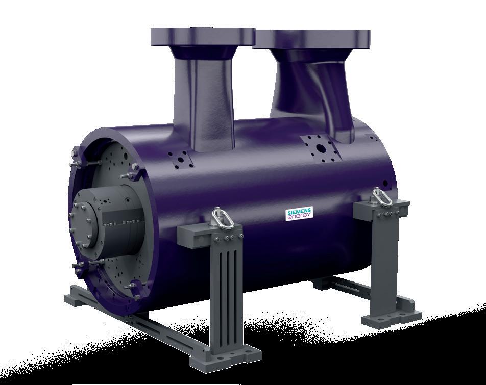
Reciprocating compressors
Unlike turbocompressors, reciprocating compressors work on the principle of positive displacement. As a result, the low molecular weight of hydrogen does not compromise compression efficiency. This typically makes them a more practical option for hydrogen service in many applications, including pipelines and electrolysis plants, which often operate at partial loads. Siemens Energy currently has more than 2 million hp of reciprocating compression installed in hydrogen-rich services, including tail gas, feed gas, and make-up services, as well as pipeline and storage.
Achieving a pressure ratio of 4:1 in a pure hydrogen application can typically be accomplished with a reciprocating compressor in just two stages. In pipelines, transport capacities of as high as 750 000 Nm³/hr can be achieved by increasing drive power and operating units in parallel.4
Hydrogen’s smaller molecular size relative to natural gas does mean that certain modifications to seals may be required to minimise internal and external leakages. Other design areas that require attention include compressor valves, lubrication, and capacity control. In many cases, these modifications can be made without replacing the entire compressor.
New compressor installs
For new hydrogen compression applications, the optimal compressor choice will ultimately be dictated by several variables, including the facility’s footprint, CAPEX, OPEX, availability/reliability, turndown requirements, etc.
Both reciprocating and turbocompressors can handle a broad range of operating scenarios, with the choice of technology based on economic trade-offs and the specific requirements of the pipeline, including required flow rates, pressure ratios, use of dry or wet sealing, and the percentage of hydrogen in the admixture.
While the specific production method (e.g. electrolysis, steam methane or auto-thermal reforming, coal regasification, etc.) is irrelevant – as compressors do not see ‘colour’ – there are several key characteristics of the hydrogen that must be considered, such as gas composition, water content, wet vs dry flow, suction pressure, gas temperature, lube-oil carryover, etc.5
40 Spring 2023 GlobalHydrogenReview.com
Figure 1. Pressure curve when transporting methane and hydrogen with the same energy content in a 100 km long high-pressure pipeline with a diameter of 1000 mm.
Figure 2. Siemens Energy’s STC-SVm turbocompressor platform.

For end users, failure to specify these values to OEMs early in the design process can result in a number of undesirable outcomes, including higher costs, reduced performance, and higher power consumption.
Compressor drivers
Blending hydrogen with natural gas will also necessitate modifications to compressor drivers (in some cases). Many compression stations across Australia are in highly-remote regions and thus rely on burning pipeline gas for drive power. Turbocompressor trains typically use gas turbines as mechanical drives or occasionally to drive generators for onsite electricity production.
Under adiabatic and stoichiometric conditions, the flame temperature of hydrogen is more than 300˚C higher than natural gas. Laminar flow speed is also higher for certain flame temperatures. This introduces unique challenges when it comes to combustion system dynamics and subsequently achieving acceptable emissions levels from the turbine.
In recent years, OEMs have made a great deal of progress in adapting gas turbines for hydrogen. Siemens Energy, for example, currently has more than 55 hydrogen gas turbines installed around the world, which have amassed > 2.5 million hours of operating experience. The company has established an ambitious goal of making all turbine models 100% compatible with hydrogen by 2030.
Today, units of varying sizes and combustion system types (e.g. unabated diffusion flame, wet low emissions [WLE], dry low emissions [DLE]) can reliably handle fuel admixtures with high contents of hydrogen. As is the case with compressors, the decision to modify an existing gas turbine or replace it will depend on several factors, including the hydrogen content in the admixture, the age of the unit, required drive power, objectives of the operator, etc.
Looking ahead
In the coming years, as production of green hydrogen in Australia increases, so too will the need for dedicated pipelines that can efficiently transport hydrogen from electrolysis plants to processing facilities (e.g. e-ammonia or e-methanol plants) and export terminals. Much of the demand in the near-term will be for short-distance, pure hydrogen lines. However, establishing a robust hydrogen economy over the coming decades will necessitate leveraging the country’s 39 000+ km of existing natural gas infrastructure.
While further research and development work on the part of OEMs will be required in order to optimise equipment for hydrogen, the challenges of hydrogen transport can largely be addressed using today’s technology. The key moving forward will be to establish a clear regulatory framework so that operators can plan and make investments accordingly.
References
1. Australian Government Department of Climate Change Energy, the Environment and Water, https://www.energy.gov.au/data/renewables
2. ‘Tracking Australia’s progress on becoming a global supplier of clean hydrogen’, S&P Global, (20 April 2022), https://www.spglobal.com/ commodityinsights/en/ci/research-analysis/tracking-australiasprogress-global-supplier-clean-hydrogen.html
3. ADAM, P., ‘Opportunities and Challenges in Converting Existing Natural Gas Infrastructure for Hydrogen Operation’, paper presented at the Abu Dhabi International Petroleum Exhibition & Conference, Abu Dhabi, UAE, (November 2021), https://doi.org/10.2118/208033MS
4. ADAM, P., HEUNEMANN, F., VON DEM BUSSCHE, C., ENGELSHOVE, S., and THIEMANN, T., ‘Hydrogen infrastructure – the pillar of energy transition. The practical conversion of long-distance gas networks to hydrogen operation’, Siemens Energy, https://assets.siemensenergy.com/siemens/assets/api/uuid:3d4339dc-434e-4692-81a0a55adbcaa92e/200915-whitepaper-h2-infrastructure-en.pdf
5. ABLONDI, T., and BARTON, M., ‘Compressors are hydrogen ‘colour blind’’, CompressorTech2, (11 August 2022), https://www. compressortech2.com/news/compressors-are-hydrogen-colourblind-/8022620.article
42 Spring 2023 GlobalHydrogenReview.com
Figure 3. Hydrogen-burning capabilities across Siemens Energy’s gas turbine portfolio.
We understand how you need to reduce complexities at your plant.


CLEAN PROCESS + CLEAR PROGRESS


You strengthen your plant’s safety, productivity and availability with innovations and resources.


Endress+Hauser helps you to improve your processes:


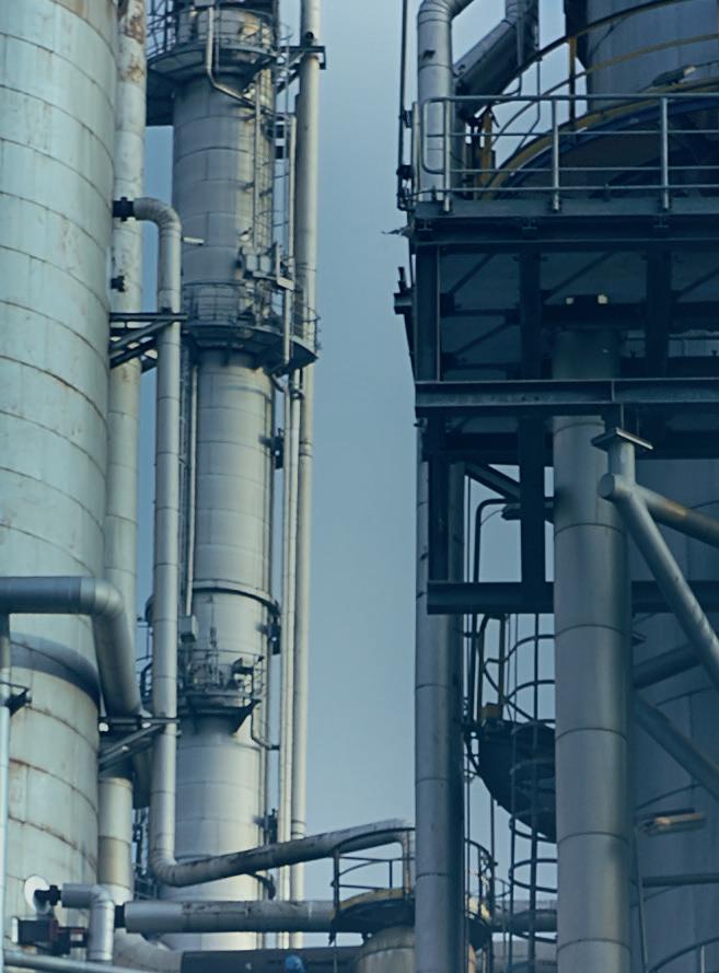
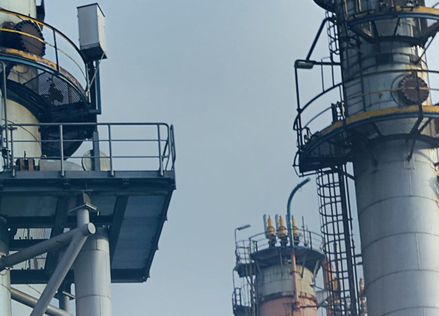


• With the largest portfolio of safety instruments that comply with international regulations


• With applied technologies and people who have extensive industry application know-how


• With access to accurate and traceable information

Do you want to learn more? www.endress.com/oil-gas


44
There is extraordinary momentum behind the deployment of clean hydrogen technologies – not only to support the implementation of environmental policies, but also to foster economic growth, and for several countries to reduce their dependency on energy imports.
Green hydrogen production from renewable energy is projected to soar in the coming years. The EU, for instance, has set an ambitious target of producing 10 million tpy of renewable hydrogen by 2030. We are witnessing the first major steps towards achieving this objective, with several projects under execution in the 50 – 200 MW range, and a rapid expansion of the project pipeline.
Typical pressure levels for hydrogen applications
Because hydrogen is a highly versatile feedstock and energy carrier, its range of end use applications is broad, covering multiple sectors. Each application has specific needs in terms of delivery pressure (see Figure 1).
Compression is therefore required for nearly all applications, even when hydrogen is produced using pressurised electrolysers. The required compression energy and the associated costs increase considerably when the starting point is hydrogen at atmospheric pressure, as they are correlated with the ratio between the outlet and inlet pressure. As an indication, machines with roughly equal shaft powers are required to compress the same flow rate of hydrogen from 1 bar to 30 bar, or from 30 bar to 900 bar.
Renewable hydrogen production relies on electrolysis – a rapidly evolving technology arena. Based on hydrogen outlet pressures, these can be clustered into two main categories: y Systems operating just above atmospheric pressure.

y Pressurised systems, which can deliver hydrogen at 15 – 40 bar.
Solid oxide electrolysis cell (SOEC) technology should also be considered, given its high electrical efficiency and relevance for industrial sites, where medium temperature heat is available, and for co-electrolysis applications. All SOEC systems currently run at atmospheric pressure. This will likely not change, given the already demanding material selection and design issues associated with the very high operating temperatures (750 – 850°C) of these stacks.
Advantages and drawbacks of atmospheric electrolysis
The selection of electrolysis technology for renewable hydrogen projects is not straightforward. There are a number of arguments in favour of selecting atmospheric electrolysers. However, project developers will be unavoidably faced with several disadvantages, many of which are linked to downstream compression equipment.
45
Octavian Partenie, Pascal Pasman, Svitlana Snelder and Theo Peperkamp, Howden, explain why it can be challenging to design reciprocating compressors for hydrogen produced at atmospheric pressure.
Advantages
y The stacks are significantly cheaper to manufacture (simpler construction, lower cost materials, not subjected to Pressure Equipment Directive [PED] requirements).
y Electrolyser auxiliary equipment will also be cheaper (water purification and circulation, cooling units, etc).
y Inherently safer designs (no pressure build-up, lower hydrogen inventory).
y Lower inspection and maintenance OPEX.
y There is an extensive track record of deploying comparable technology from the chlor-alkali and ammonia industries, enabling some suppliers to provide guarantees of performance.
Drawbacks
y A low-pressure compression step is required, which greatly increases compression CAPEX.
y Energy-related OPEX will also increase substantially for the compression step, due to the much higher pressure ratios.
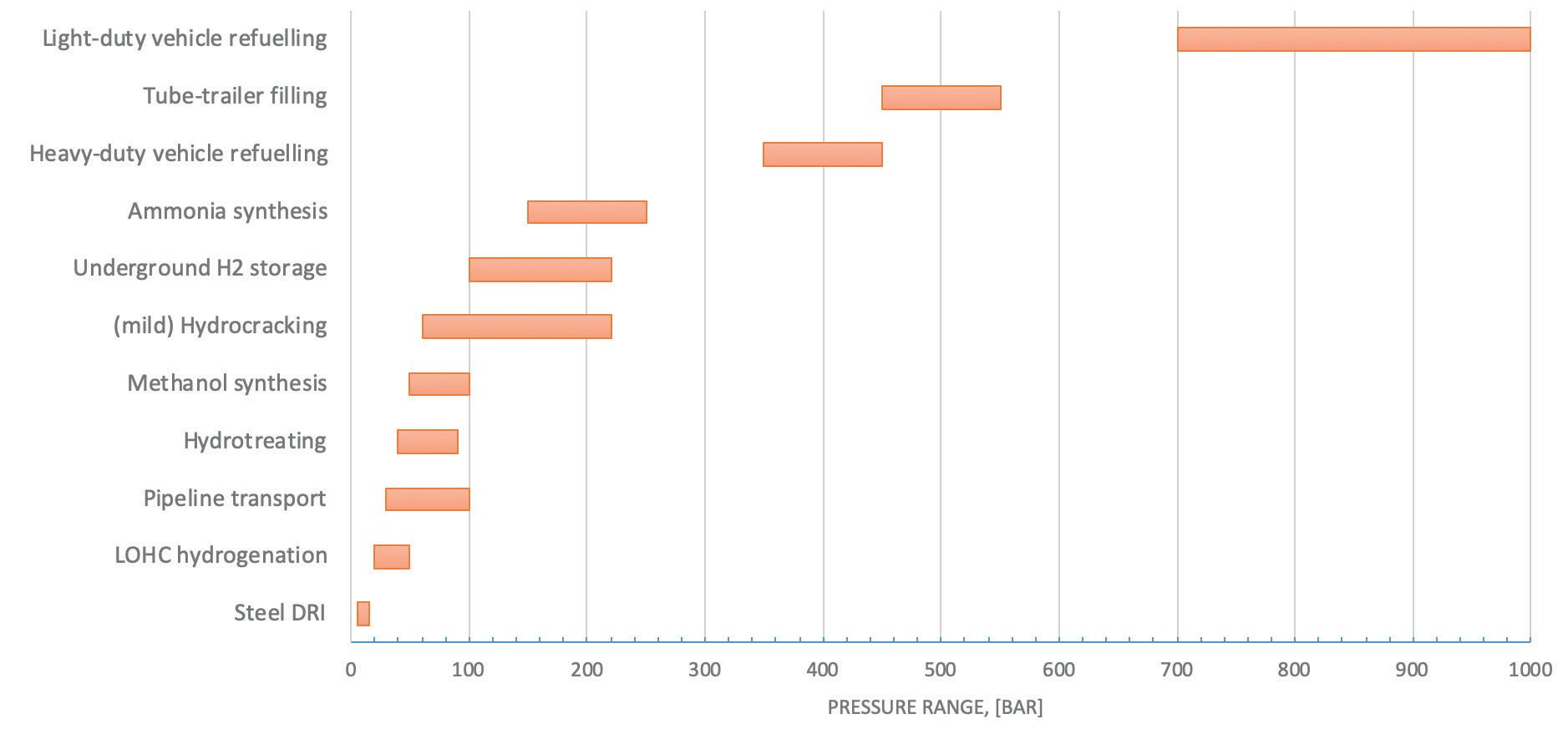
y Large-diameter gas transfer lines are needed.
y There could be a higher risk of equipment damage during transient operation (start-ups, shutdowns, upset scenarios).
y For reciprocating machines, a buffer volume is required, and an integrity study must be carried out to prevent electrolyser damage caused by flow pulsations.
Addressing the challenges of atmospheric hydrogen compression
Compressing hydrogen gas from just above atmospheric pressure poses specific challenges for reciprocating compressor designs. To start with, the gas density of pure hydrogen is extremely low at 1 atm (approximately 0.09 kg/m3), resulting in huge volumetric flow rates for the first compression stages. When the maximum cylinder capacity is exceeded, this means that the first stage requires multiple cylinders in parallel.
Howden adapted its reciprocating compressor design to increase the maximum hydrogen flow per single frame, by
increasing the cylinder diameter and adjusting the frame design to fit the larger-diameter cylinders. An example is shown in Figure 2. For large projects (100+ MW of electrolysis capacity), however, the volumetric flows are pushing against the manufacturing limits for compressor cylinders. Selecting large-diameter cylinders for the first stages also presents challenges in terms of fitting these cylinders on existing frames, as well as maintaining sufficiently large gaps for inspection and maintenance access.
If the maximum frame capacity is exceeded for the combination of hydrogen flow rate and outlet/inlet pressure ratio required by a project, two or more machines will be required, increasing CAPEX. This could, however, be beneficial for operational flexibility and availability. Selecting the overall best configuration requires a techno-economic evaluation (TEA) to be carried out.
Online condition monitoring and preventive maintenance are particularly valuable for large reciprocating compressors with multiple cylinders, avoiding unplanned downtime. Howden Uptime enables comprehensive equipment performance tracking and early-stage fault detection. The digital platform also grants operators access to updated asset documentation and remote assistance from Howden original equipment manufacturer (OEM) specialists.
Another issue related to large-diameter cylinders is that correspondingly-large pistons are required, which will be much heavier, therefore increasing rider ring wear. This issue can be overcome by Howden’s Free Floating Piston technology (FFP™), the working principle of which is illustrated in Figure 3. In addition to reducing wear and ensuring a longer mean time between overhauls, FFP technology enables oil-free gas compression, maintaining a high hydrogen purity without the need for coalescing filters. This solution also allows for the operation of the compressor at higher piston speeds compared to conventional non-lubricated designs. This means that larger flows are possible for a given design, or that smaller cylinder sizes can be selected in the design phase.
46 Spring 2023 GlobalHydrogenReview.com
Figure 1. Typical pressure ranges of common applications for (renewable) hydrogen.
When reciprocating machines are installed downstream of atmospheric electrolysers, specific attention is required in the design phase to avoid the risk of equipment damage. Flow pulsations on the suction side of the compressors could rupture the relatively fragile cell membranes, for instance. A way to mitigate this is to add a sufficiently large buffer volume between the two sections of the plant, acting as a dampener. Such a buffer vessel or gas holder will ensure a relatively constant pressure at the compressor inlet. Another option would be to select a non-reciprocating type of compressor for this low-pressure duty – a water-injected screw compressor, for example.
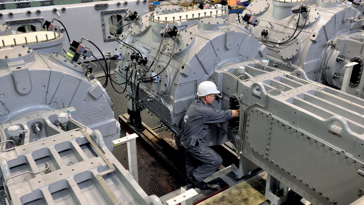
Lastly, in the case of atmospheric alkaline electrolysers, the hydrogen gas will be contaminated with potassium hydroxide (KOH). Since hydrogen produced at the cell membrane bubbles out of the aqueous KOH solution, it leaves the stack saturated with water vapour. The impact of the gas composition on the compressor design has to be carefully evaluated, as it is not practical to fully separate the KOH and water from the hydrogen stream at low pressure.
To counter the potential long-term effects of KOH in relation to caustic dewpoint corrosion and stress corrosion cracking, a possible solution is to select stainless steel as the construction material for pulsation dampeners, inter-stage coolers, and separators. This has cost implications though, as the metal price can easily be a factor three or four times higher compared to high-strength carbon steel.
Large-diameter compressor cylinders and pistons are manufactured by casting, so selecting stainless steel is not viable. Instead, for a recent project, advanced calculations were carried out to reinforce the cylinders at locations where contact with KOH is expected to cause wear.
There are also many small- to medium-scale renewable hydrogen projects (5 – 50 MW) under development. When selecting atmospheric electrolysers, developers face the same challenges that have been discussed, while typically also requiring a more compact solution for the compression step. For such applications, Howden has developed a dedicated solution in the form of a compact reciprocating compressor design. These machines have a small footprint, and are delivered fully-packaged as skid-mounted units (see Figure 4), greatly reducing installation time onsite, and reducing the risk of running into issues during commissioning and start-up.
Current non-lubricated designs can achieve outlet pressures of up to 200 bar, starting from atmospheric pressure. It is economical to equip these units with variable frequency drives (VFD), which enable stepless flow control in the 50 – 100% capacity range.
For applications where a higher discharge pressure is required, e.g. tube-trailer filling, hybrid solutions are available, incorporating a diaphragm machine for the final compression steps. As diaphragm machines are normally driven by VFDs, they can be installed in series with a reciprocating piston compressor, with minimal buffer volume in between.
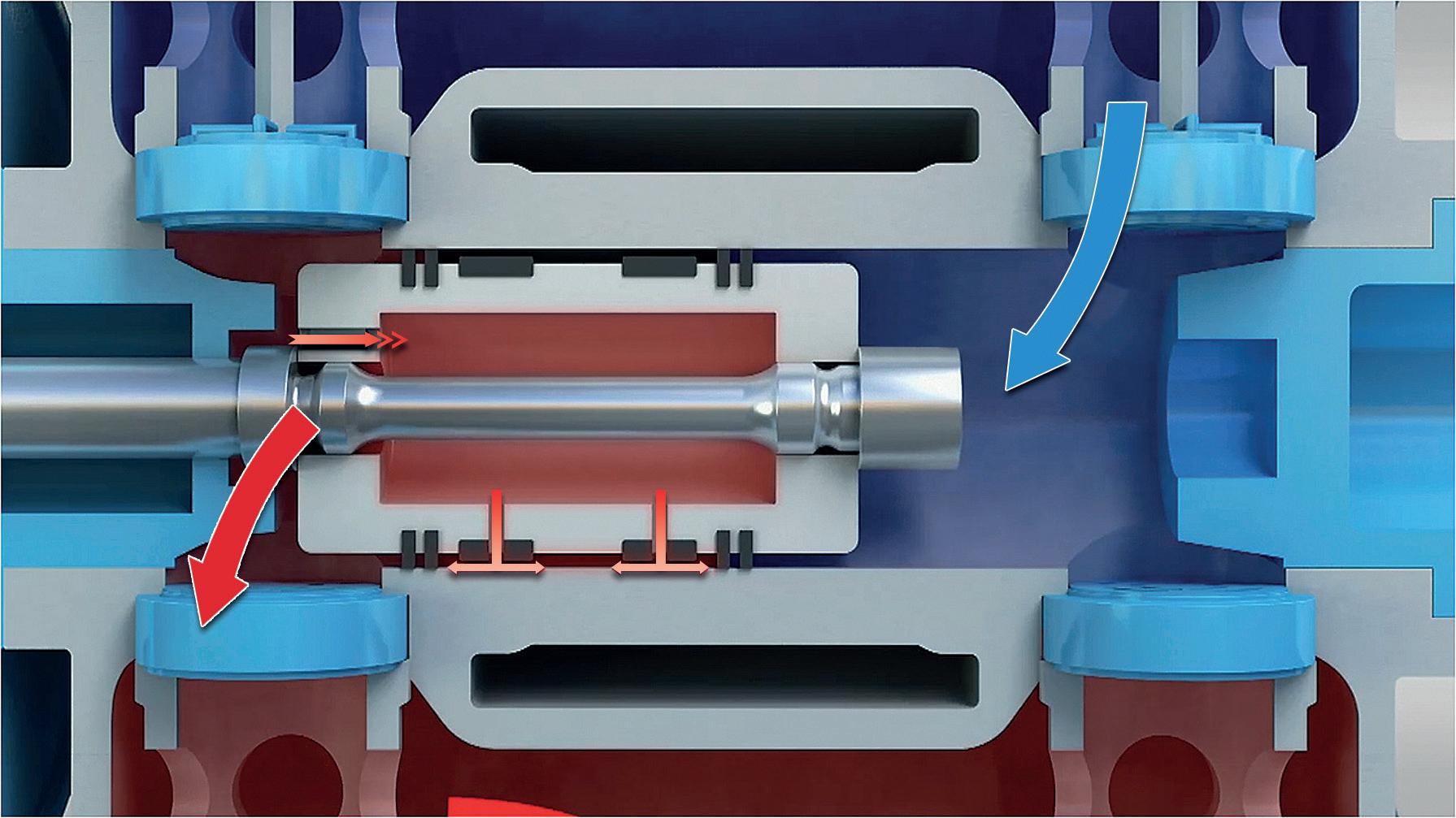
Conclusion
When selecting compression equipment, it is important to partner with a company that has the knowledge and experience of designing fit-for-purpose compression equipment, and that closely collaborates with customers to
ensure that the right compressors are selected for various elements of hydrogen value chains. As global demand for renewable hydrogen solutions rapidly increases, pressure is placed on the equipment supply chain, and companies are responding to this by expanding factory capacity and streamlining the manufacturing process to reduce cost and delivery times in order to support project developers and contribute to the success
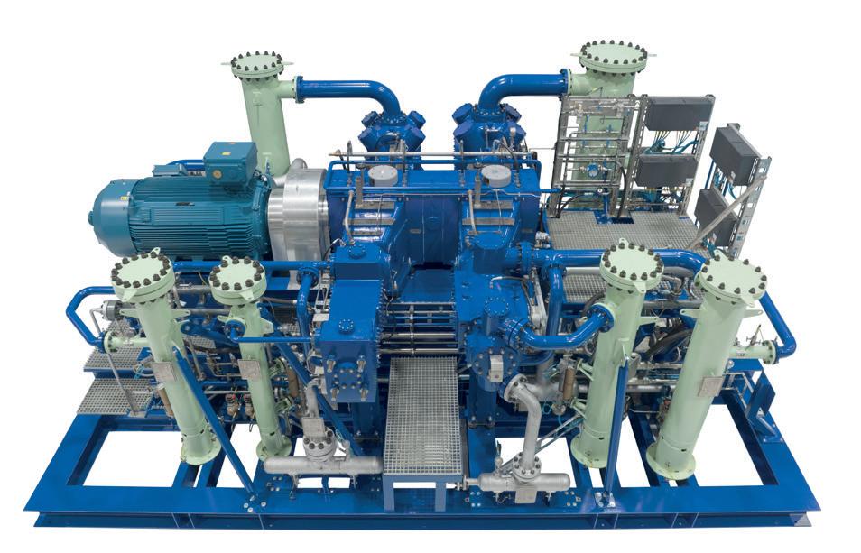
Spring 2023 47 GlobalHydrogenReview.com
of this emerging industry.
Figure 2. Example of a Howden reciprocating compressor design with large-diameter cylinders.
Figure 3. Schematic representation of Howden’s FFP working principle. Process gas enters the piston during the compression stroke and is forced out through nozzles integrated into the bottom of the rider rings. This forms a thin film of pressurised gas, which supports the weight of the piston.
Figure 4. Example of a skid-mounted Howden reciprocating compressor design, with six stages, which compresses 200 kg/hr of hydrogen from atmospheric pressure to 200 bar.
According to Forbes, the hydrogen economy will soon be ready for takeoff given the strong global investment and desire to make hydrogen a leading sustainable source of energy.1 Hydrogen sensing will play a critical role in making this goal a reality. This article will provide insights into the use and impact of hydrogen sensors, both in current applications as well as within the emerging hydrogen economy.
What is a hydrogen sensor?
Hydrogen is the lightest and most abundant element in the universe, and one would think that developing a device to measure its concentration in a gas or liquid would be simple. Unfortunately, this is not the case; it took many years of research and development – from the early days when canaries were used to detect explosive gases in mines. The first sensor of the modern age was developed in 1926 by
Dr. Oliver Johnson of Standard Oil Co. His design measured the heat created by the presence of combustible gases in air. This thermal conductivity technology is still used today, along with a range of new gas sensor technologies that have been developed over the last 100 years. Each of these technologies (e.g. gas chromatography, catalytic bead, laser gas analysis, solid-state, etc.) were developed to address unmet gas sensing needs, and there are many issues to consider when applying these technologies to hydrogen sensing.
What to consider when selecting a hydrogen sensor for industrial applications?
Industrial sensing applications generally have challenging performance and operational requirements that must be met over a range of environmental and other conditions. Care must be taken to ensure that the selected sensor

48
and underlying technology works for the intended use, for example:

� Sensor performance may seem like a straightforward specification, but the devil is in the details. For example, a quoted measurement accuracy of 0.1% could be the maximum error, or it could be the one sigma error, or it could only be valid at room temperature and one atmosphere of pressure. Also, the quoted accuracy specification may only be met after calibration for a specified period before drifting out of specification.
� If other gases are present in the stream being measured, they could impact sensor accuracy. For example, carbon monoxide (CO) in a hydrogen stream can corrupt the hydrogen measurement when using certain gas sensing technologies. One must understand the gas stream make-up and consider using a hydrogen-specific sensor to avoid cross-gas sensitivities.
Meyers, H2scan,
� From a total cost of ownership perspective, sensors should be selected to minimise or avoid calibration, maintenance and service if possible. Some hydrogen sensor technologies have consumables, such as calibration gases, that must be periodically replaced. Also common is the need for sensor calibration to maintain long-term accuracy. One should understand the calibration interval and the associated costs, especially for remote or hazardous locations, or whether the system needs to be shut down for this maintenance. Beyond the upfront cost of the sensor and its installation/connectivity, one should consider the total cost – including the cost of training operation support professionals.
� If the sensor is not reliable, sending a service team to an oil platform or remote pipeline location takes a great deal of time, effort and expense. Sensor technologies requiring numerous mechanical parts and components, such as gas
49
COVER STORY
David
USA, discusses the importance of hydrogen sensing within the emerging hydrogen economy.
extraction systems to measure hydrogen in liquids, are often not well-suited for these applications. One should strive for a long life, with a goal of over 10 years.
y Hydrogen is an explosive gas, and a small spark can cause it to explode within certain concentration levels. There are certifications, such as ATEX, to ensure that sensors work safely in hazardous environments. Sensor compliance to these certifications is critical to ensure safe operation.
Where are hydrogen sensors being used now?
The largest hydrogen user today is refining and chemical production. One such application is hydrocracking, which uses hydrogen sensors to ensure efficient processing. One of the challenges of oil processing applications is gas streams that can contain multiple other gases, such as hydrogen sulfide (H2S). These gases can reduce the measurement accuracy if the sensor is not a hydrogen-specific design. Also, the sensor needs a fast response time to ensure tight process control when concentration levels fluctuate, in order to achieve optimal process efficiency.
Another common application for hydrogen sensors is area safety monitoring for the detection and mitigation of hydrogen build-up in a closed environment. For example, in data centres and utilities, battery back-up systems are used to provide instantaneous back-up power. Cost-effective energy storage solutions such as lead acid batteries are commonly used, and can release hydrogen during recharging. A similar application is hydrogen fuel cell forklifts that could potentially leak. In both applications, hydrogen sensors are generally mounted in the
ceiling to trigger alarms and enable fans to evacuate hydrogen at concentrations well below the lower explosion limit of approximately 4%.
One hydrogen sensor application that many people are unaware of is transformer monitoring to improve electrical grid reliability. Power on the grid is distributed using large transformers that convert high voltage to a lower voltage for end users. These devices are filled with oil to keep them cool and provide electrical isolation. If there are faults or overheating in the transformer, the oil will break down into hydrogen and other gases. If faults persist for too long, the transformer can explode and cause a fire, or injure people. Hydrogen sensors are used to continuously measure hydrogen levels in the oil to determine the need for maintenance or to take the transformer offline.
Why are hydrogen sensors important to the hydrogen economy?
The goal of the hydrogen economy is to use hydrogen to help decarbonise the energy supply chain – from production to consumption. As stated in the ‘Road Map to a US Hydrogen Economy’, safety is paramount.2 This is a precondition of any energy carrier, but as hydrogen is a greenhouse gas (GHG), leak detection is critical for its wide deployment.
Most hydrogen produced today is from fossil fuels, and is referred to as grey hydrogen because one of the byproducts is carbon dioxide (CO2). The hydrogen economy goal is to produce green hydrogen from renewable energy and to adopt fuel cells, gas turbines or other means for the subsequent conversion back into electricity. Hydrogen is also planned to be distributed through gas pipelines for industrial uses, home heating, and as a transportation fuel. Hydrogen sensors will play an important role across these applications to ensure safe and effective operation, as well as the detection of harmful leaks.
What is next for hydrogen sensors?
There are numerous near-term hydrogen economy applications that require hydrogen sensors for safe and effective operations.
The production of green hydrogen uses electrolysers that convert water into hydrogen and oxygen using a process called electrolysis. Some analysts are predicting that up to 85 GW of electrolyser-based hydrogen production will be deployed by 2030. If there are issues in the electrolyser, hydrogen can leak into the oxygen output side, creating an explosive mixture. Detection of this failure mechanism is critical to ensuring the safe operation of these systems.
Hydrogen will also be blended with natural gas and sent through the gas pipeline as part of the decarbonisation plan. Home and industrial heating is a large user of natural gas, and replacement electricity in the near-term will be a challenge. To put this into perspective, natural gas delivers five times the energy of the electric grid in the UK.
To use hydrogen safely, all gas pipeline infrastructure, burners and metering in the gas distribution network must be aligned to support a mixture of methane and hydrogen. Gas blending stations will use a hydrogen sensor to ensure that the mixture is the right concentration for safe operation. Along the distribution pipeline, hydrogen sensors could be used to confirm downstream concentration and support energy

50 Spring 2023 GlobalHydrogenReview.com
Figure 1. Hydrogen sensor (in green) mounted to an electricity transformer.
OUR MAX UPTIME IS YOUR SUCCESS

Burckhardt Compression offers compressor solutions over the entire value chain of hydrogen for mobility and energy. Our oil-free diaphragm and piston compressors (550 bar) stand for the highest reliability and gas purity at minimal maintenance costs and energy consumption. The global network of Burckhardt Compression local service centers enables us to perform local support with quick response time, ensuring the highest uptime for your business. Learn more: burckhardtcompression.com/hydrogen
metering and customer invoicing. Finally, hydrogen sensors could be used for home safety, much like a smoke alarm, to ensure that leaks are detected early before hazardous concentration levels are reached.
In transportation, there has been success in large vehicles using hydrogen, and there have been regional pilot programmes in small vehicles as well. These vehicles use fuel cells which use hydrogen and oxygen to make electricity, and output water. If hydrogen is not fully utilised or it leaks into the exhaust water, there can be risks associated with the out streams from these devices. In addition to large vehicles and personal vehicles, fuel cells are also being used for hydrogen-fuelled forklifts. Once again, hydrogen sensors will be used to detect hydrogen leaks to ensure safe operations in this application.
Conclusion
The future of the hydrogen economy is bright and will be an important part of global decarbonisation initiatives. Hydrogen sensors will play a critical safety role in many aspects of the development and eventual deployment of a global hydrogen economy – in industrial applications as well as in the home.

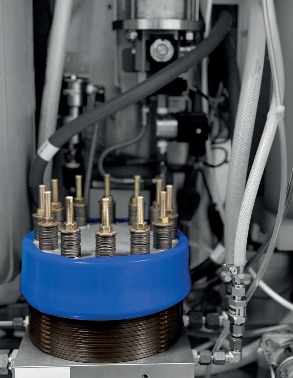
References
1. ‘The Hydrogen Economy Will Soon Be Ready For Take Off, Including Planes And Power Plants’, Forbes, (6 November 2022), https://www.forbes.com/sites/kensilverstein/2022/11/06/thehydrogen-economy-will-soon-be-ready-for-take-off-includingplanes-and-power-plants/?sh=7779619c4451
2. ‘Road map to a US hydrogen economy’, https://static1.squarespace. com/static/53ab1feee4b0bef0179a1563/t/5e7ca9d6c8fb3629d399 fe0c/1585228263363/Road+Map+to+a+US+Hydrogen+Economy+F ull+Report.pdf
The premier source of information for the renewable energy industry Subscribe for free at www.energyglobal.com The premier source of information for the renewable energy industry Subscribe for free at www energyglobal.com EG_Web_ad.indd 2 13/07/2020 13:06
Figure 2. An electrolyser is used in the manufacture of hydrogen. The industry is working to produce green hydrogen using electrolysers and clean energy sources.
Global efforts to protect the environment have increasingly focused on lowering carbon emissions. Dr. Florian Adler and Jim Belanger, Process Insights, suggest that the key to meeting this challenge lies in replacing fossil fuels with alternative, renewable fuel sources, particularly to power vehicles.
Hydrogen fuel cells offer a flexible solution to lowering emissions, and can be used for a wide range of applications – powering a number of systems, from laptops to utility power stations. The move to a hydrogen economy is widely regarded as the next step in the global transition towards a zero-carbon energy sector. A hydrogen fuel cell uses chemical energy to cleanly and efficiently produce electricity: by combining hydrogen and oxygen via a catalytic process, the fuel cell can harness the energy of this reaction very efficiently, and the only byproducts are water and heat. As the fuel cell directly produces electricity, it can also be readily combined with electric motors to power a zero-emission vehicle. While most hydrogen is still produced from

53
fossil sources, an established hydrogen infrastructure allows for a seamless transition to renewable and truly carbon-free hydrogen production in the future.
Fuel cells’ most interesting application is for use in vehicles. A decade ago, fuel-cell-powered cars were widely viewed as the future of the automotive industry; however, they have been leapfrogged by battery electric vehicles (BEVs) in recent years due to the tremendous progress in battery technology and the massive investments in public charging infrastructure, in addition to the possibility of charging the vehicle at home. For fuel cell vehicles, the current lack of widespread availability of hydrogen fuelling stations is a major shortcoming at present. As such, when it comes to putting the new technology on the road, BEVs clearly have the most momentum at the moment. They offer high efficiency and are likely an excellent option for people driving occasionally or commuting to work. However, fuel cell vehicles offer some key advantages that make them a superior choice for long travel distances, commercial traffic, and fleet vehicles.
Fuel cells are far more efficient than conventional combustion engines, yet offer a similar range (approximately 500 – 700 km for a passenger vehicle). Most importantly, hydrogen can be refilled quickly at a fuelling station in a matter of minutes, avoiding the delays of charging a BEV. This charging time can add up substantially for a long trip across continental US or Europe, for instance. Additionally, in order to offer adequate range with a battery, it must be fairly large and heavy, which means lower efficiency and payload. The same amount of energy stored in hydrogen is significantly more compact, and lighter. Even fuel-cell-powered aircraft are being developed for this very reason. In short, fuel cell vehicles promise to be an ideal emission-free solution for applications where batteries do not offer an adequate replacement for conventional fuel.
Real-world usage of fuel cell technology
While fuel cell technology is in its infancy in many areas, there are promising examples of real-world implementation. When it comes to road vehicles, California, US, offers a glimpse into a future of hydrogen-based transportation. According to the Hydrogen Fuel Cell Partnership, 54 fuelling stations are currently available across the state, with 115 more in development.1 The majority are located around the major population centres, and increasingly along major highways as so-called ‘connector stations’, where vehicles can refuel while travelling across the state. Meanwhile, fuel cell vehicle deployment focuses on passenger vehicles and commercial buses. In other areas of the world, hydrogen networks are also developed. There are many initiatives in European and Asian countries, with China aggressively pursuing fuel cell technology at present. In recent years, the country has implemented fleets of fuel cell buses in several cities, for instance. These buses for local public transportation have also been tested in a number of other communities worldwide.
One area in which fuel cells have already had a major impact is forklifts. While this may seem surprising, tens of thousands of fuel-cell-powered forklifts are in operation at warehouses across the globe. By 2027, the market size for fuel cell forklifts is estimated to top US$5 billion.2 Despite the continued
high cost of fuel cells, warehouses offer a niche for this technology: in contrast to combustion-engine forklifts, there are no emissions, which is important in indoor environments. Compared to battery-electric forklifts, those that are fuel-cell-powered can operate 24 hr/d, with just minutes of refuelling time in between. Obtaining the same uptime with batteries requires purchasing sets of spare batteries that can be swapped in and out periodically to overcome the long charging time. Ultimately, fuel cell forklifts fulfill the zero emissions requirement, and beat electric forklifts in terms of long-term operating cost.
Hydrogen quality and fuel cell performance
One key issue with fuel cells is that their performance is dependent on the purity of the hydrogen. This statement is not too surprising; almost any engine will suffer from poor performance or even damage when the fuel quality is not adequate – something that is equally true for combustion engines and fuel cells. However, even very low levels of certain impurities in the hydrogen can have a detrimental or devastating impact on the fuel cell. Proton exchange membrane (PEM) fuel cells are the dominant type for vehicle applications, and have two critical components: the catalyst, which separates the hydrogen into protons and electrons, and the PEM, which must transport the protons from the anode to the cathode as efficiently as possible. As a result, purity requirements for certain contaminants that have a strong effect on the performance of the catalyst and the PEM must be stringent.
International hydrogen purity standards, such as ISO 14687 or SAE J2719, have been designed to set contaminant limits that prevent harm to the fuel cell, which can range from hundreds of parts per million (ppm) for relatively benign contaminants such as nitrogen or argon, to low parts per billion (ppb) (for more harmful species, such as carbon monoxide [CO] or sulfur compounds). Sulfur poisoning, in particular, can contaminate a fuel cell permanently, and the resulting loss in efficiency is non-recoverable and may necessitate a complete replacement of the fuel cell. CO is probably the second most critical contaminant. While CO poisoning is considered recoverable, it is not a simple procedure, and any fuel cell vehicle would certainly be stranded on the road.
Origin of impurities in hydrogen
Most impurities found in hydrogen fuel are remnants of molecules contained in the raw material. For most of the hydrogen produced in the US, for instance, this raw material is natural gas. Natural gas contains mostly methane, which must be reduced to trace levels in the hydrogen end product. It also contains other hydrocarbons, CO and carbon dioxide (CO 2 ), water, and various sulfur compounds, such as hydrogen sulfide (H 2 S), carbonyl sulfide (COS), and mercaptans. The steam methane reforming (SMR) process that generates hydrogen from natural gas demands various steps and multiple levels of purification to successfully meet the strict purity requirements for fuel cell grade hydrogen, but eliminating impurities from hydrogen altogether is not practical.
54 Spring 2023 GlobalHydrogenReview.com
VIRTUAL


An interactive Virtual Conference showcasing the innovative technology and solutions that are advancing the hydrogen industry worldwide. Register for free here: https://bit.ly/3jtoh4h
participation from:
HYDROGEN CONFERENCE 23
With
CONFERENCE
2023
Ramp up production of sustainable aviation fuel. Together we can transform the aviation industry’s carbon intensity for the better. Keep planes in the air, and still be on track to zero. SAF reduces CO2 emissions by at least 85% when compared to conventional fuel. And we have the proven technologies to make it all happen. Now. Turn your sustainable ambitions into a sustainable business. Join Flight Plan Green. Find out how: topsoe.com/saf
20 APRIL
TAKE-OFF. FROM AMBITION TO ACTION. FLIGHT PLAN GREEN
Another method to generate hydrogen is steam reforming of methanol, which can be generated as an intermediary product that is easier to transport (as a liquid). This method is more common in places without nearby access to natural gas. The most promising way to generate hydrogen in a completely carbon-free way, which should see massive expansion in the future, is electrolysis of water. The electricity necessary for this method can be generated from renewable energy, and the process can be performed onsite at a fuelling station, eliminating the need to transport the hydrogen to the site. Hydrogen generated from electrolysis has a different profile of impurities; generated from pure water, the hydrogen naturally contains less methane and fewer hydrocarbons. Ironically, water impurities tend to be less of an issue too, despite it being the main raw material, because most water contamination happens through exposure to the atmosphere via making and breaking connections during transportation, or leaks in valves and pumps. As electrolysis is mostly performed onsite, this source of contamination is largely avoided. Nitrogen and oxygen are also contaminants that are often added from the atmosphere and are therefore important components of the station compliance testing as well.
Monitoring a wide range of impurities
While impurities in hydrogen are monitored along many steps of the supply chain, only the final product dispensed at the fuelling station is typically tested for the full suite of analytes listed in the ISO/SAE standards, as required by regulations. Compliance is usually enforced by government organisations or official contractors. In most cases, samples are collected at fuelling stations and analysed in dedicated stationary or mobile laboratories.
In the past, a monitoring solution for hydrogen purity involved a complex set-up using as many as seven different analysers from multiple providers, with no integration.
A typical legacy arrangement consists of:
y A gas chromatograph for total sulfur and total halogenates.
y Another gas chromatograph for helium, nitrogen and argon, and methane/THC.
y An electrochemical analyser for oxygen.
y An FTIR to measure formic acid, CO and CO2
y Three separate Cavity Ring-Down Spectroscopy (CRDS) analysers measuring water, ammonia, and formaldehyde.
While every laboratory’s configuration varies in some respect, past set-ups do not provide an all-in-one solution. The large number and type of instruments requires technicians to be trained on many different platforms. Start-up, calibration and measurement procedures vary from instrument to instrument, thus requiring an extraordinary amount of care to ensure consistent results.
Process Insights offers a full portfolio of solutions for monitoring hydrogen purity throughout the supply chain –from production through to transport, storage and fuelling. The contaminant detection limits of these instruments are suited to qualify hydrogen for compliance with global purity and measurement standards, e.g. ISO 21087, which outlines suitable properties of analysers for hydrogen monitoring.
The company’s total solution links products from its Extrel and Tiger Optics brands. Only three analysers are required, and these can be fully integrated into one single-provider system, including:
y Tiger Optics Prismatic™ 3 multi-species CRDS analyser – for CO, CO2, water and ammonia. It allows for simultaneous detection of up to four impurities with wide dynamic ranges, delivering simple, real-time, direct measurements. It is ideal for remote operations, and has a low cost of ownership.
y Extrel MAX300-LG™ mass spectrometer – for measurements of helium, nitrogen, argon, methane, oxygen, formaldehyde, and formic acid. This is a compact benchtop mass spectrometer that delivers complete, real-time sample analysis from 100% concentration down to ppb levels. It is supported by Extrel’s Questor5 process control software, which is designed for continuous gas monitoring with automated calibrations, analysis sequences, and data outputs.
y Sulfur and THC multi-species GC iMOv analyser – for total sulfur and total hydrocarbons. This solution allows for a broad offering of standard modules which are easy to use and set up, unlike legacy GC platforms. The iMOv utilises the modular mechanical design for easy application customisation, is IIoT ready, and has a robust and embedded GC software platform.
Some points along the supply chain focus on a subset of species that are of particular concern in the respective process step. For measurements of specific analytes, Process Insights offers dedicated single-species monitors –some with extremely low detection limits. Some examples of these systems include:
y Tiger Optics HALO Max QCL – this novel CRDS system, which is based on a mid-infrared quantum cascade laser (QCL), is available to detect CO or CO2 at levels well below 1 ppb.
y Tiger Optics HALO 3 CH2O – this dedicated CRDS system specialises on the detection of formaldehyde at levels below 10 ppb.
y Tiger Optics HALO 3 NH3 – this system has a similar configuration as the above, but is designed to measure ammonia at sub-ppb levels.
Conclusion
Hydrogen fuel cells remain one of the most promising technologies to support a sustainable energy future, especially for the transportation sector. Despite the push for electrification, worldwide investments in hydrogen infrastructure are greater than ever before. To ensure sufficient fuel quality, powerful and easy-to-use analytical equipment is being developed that can be deployed at critical points along the supply chain, from production to fuelling. And, with more and more hydrogen produced sustainably, fuel cell technology provides a clear path to a greener future for the world’s energy needs.
References
1. ‘FCEV Sales, FCEB, & Hydrogen Station Data’, Hydrogen Fuel Cell Partnership, https://h2fcp.org/by_the_numbers
2. ‘Hydrogen Fuel Cell Forklift Market Size And Forecast’, Verified Market Research, https://www.verifiedmarketresearch. com/product/hydrogen-fuel-cell-forklift-market/
56 Spring 2023 GlobalHydrogenReview.com
Allan Rushforth, First Hydrogen, UK, describes how green hydrogen is supporting the UK’s transport sector on the path to becoming a net zero industry.

At a time when the political and commercial outlook is dominated by volatility and uncertainty, governments across the world are seeking ways to cool the planet, improve our air quality, and navigate the increased energy costs caused by Russia’s invasion of Ukraine.
As countries look closer to home for more secure sources of energy, and strive to improve urban air quality with vehicle emission regulations, governments are turning to renewables as a source of carbon-neutral power. This has returned hydrogen to the global agenda, after decades of development. The recent upsurge of energy prices has also led to a sharper focus on hydrogen – a fuel that has been at the margins of global energy markets for more than a generation. Whilst grey or blue
hydrogen can be produced from fossil fuels, it is so-called green hydrogen, produced from renewable energy such as wind, solar and hydro-electric sources, that is the centre of attention.
Why hydrogen?
Renewables will be responsible for almost 40% of the electricity generated in the UK in 2023, with much of this coming from both onshore and offshore wind farms. Even though governments may have problems siting new wind and solar farms, renewable energy capacity has to be scaled up as the national grid decarbonises. However, it is the requirement to efficiently balance renewable energy supply and customer demand that underpins the case for hydrogen.
57
When consumer demand for electricity falls at night, but wind turbines around the shores of the UK continue turning, hydrogen provides a means of storing the energy that they produce – often over periods of months, and at scale. This can subsequently be converted back into electricity and returned to the grid.
Yet, as it stands, an increasing portion of renewable energy is ‘curtailed’. This means that turbines are simply stopped in an effort to balance the grid when supply exceeds demand, which ultimately cost consumers close to £300 million in 2020. 1
Lightening the load
Hydrogen mobility uptake helps to decongest the grid and enables more renewable energy generation to come to market – the transport sector being the most likely first mover market for hydrogen. But without significant growth, grid balancing issues will remain and, just as importantly, reducing our reliance on fossil fuels will be harder to achieve.
Increasing investment in hydrogen-fuelled transport will not only help to reduce electricity prices for end users and improve overall grid efficiency, but also reduce carbon dioxide (CO 2 ) emissions. This makes hydrogen a champion when it comes to achieving sustainability targets, especially for transport.
Fuel cell vs battery electric vehicles
The future for zero-emission transport and mobility will most likely be a combination of battery electric and hydrogen solutions. This dual approach will help battery electric vehicle (BEV) users to capitalise on low electricity prices during periods of high production. Additionally, this will free up the grid for the charging of electric van fleets at
depots, which will be particularly useful during periods of excess demand.
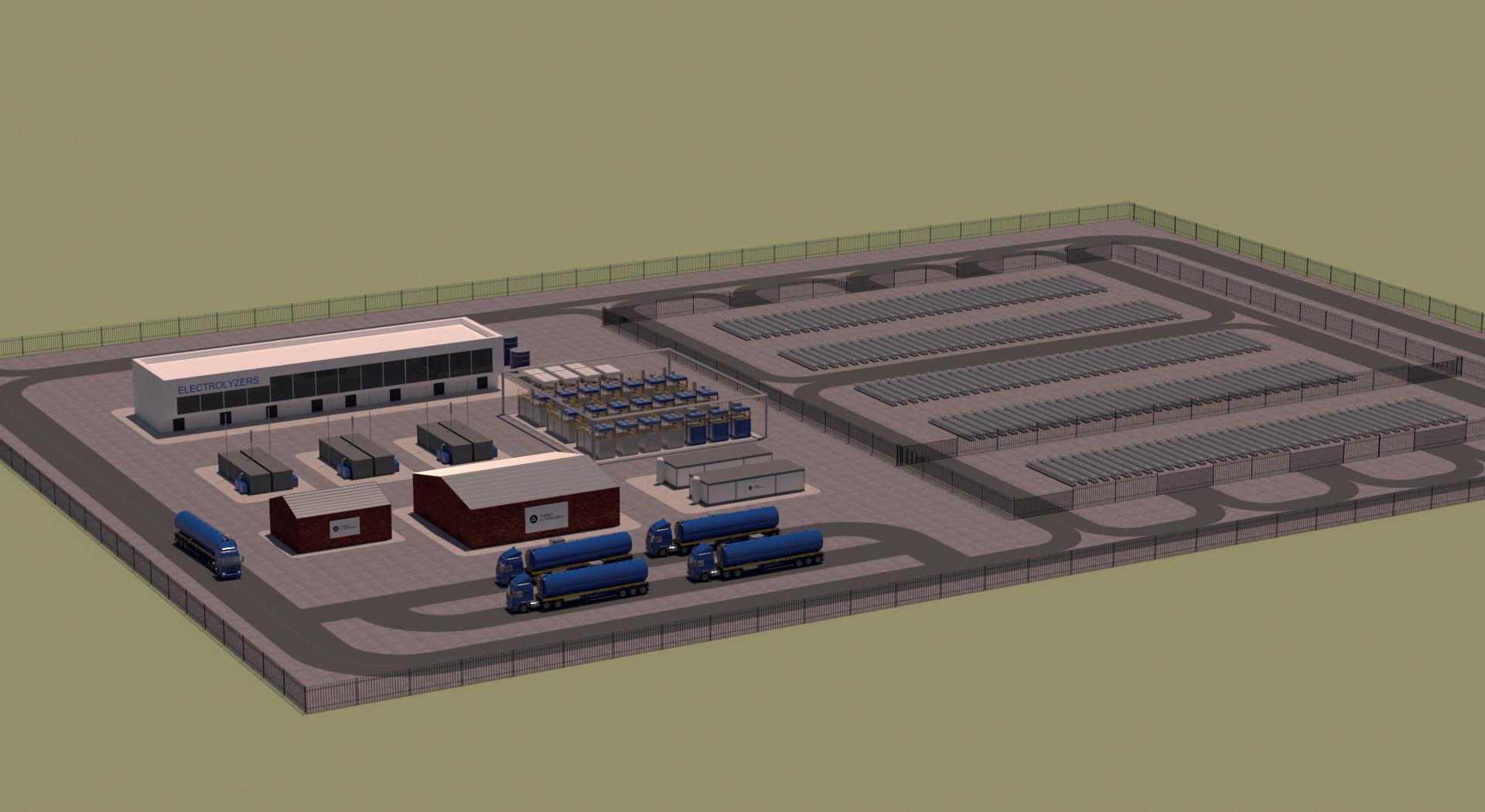
Batteries and fuel cells will operate alongside one another in the future. However, fuel cell electric vehicles (FCEVs) are superior to BEVs in terms of refuelling time, range and most importantly, payload – FCEVs are lighter and therefore more suited to carrying heavier loads. When considering entire vehicle fleets, these factors result in increased fleet productivity as businesses benefit from buying and parking fewer vans, thereby reducing personnel costs, creating more uptime for the vehicles, and reducing capital and maintenance costs as a result. The cumulative effect is less wasted energy i.e., in-depot conversion and infrastructure installation, resulting in lower overall emissions.
Barriers to hydrogen adoption
Whilst the development of hydrogen-powered transport is following a similar pace and trajectory, the market for hydrogen and the associated mobility technology still has a way to go to rival that of electricity and BEVs. However, the speed of development of hydrogen-powered vehicles is accelerating. FCEV drivetrain efficiency has improved by 300% over the last decade, and the efficiency of hydrogen production has more than doubled over the same period as new electrolyser technologies become available – often at lower prices.1
At a time of increasing demand for hydrogen and ever-higher prices for the electricity used to produce it, it is likely that hydrogen prices will also rise over the short-term. This is due, in part, to a failure to decouple renewable energy prices from those of gas. Challenging the so-called ‘merit order’ that links renewable energy prices to natural gas would allow consumers to benefit from the
58 Spring 2023 GlobalHydrogenReview.com
Figure 1. Visualised green hydrogen production.
improving availability of wind and solar power at more competitive prices. However, this would have to be done whilst taking account of the UK government’s Contracts For Difference (CfD) that provide developers with longer-term stability of pricing for their renewable energy.
Even without these changes, the total cost of ownership (TCO) for FCEVs, which is currently forecast to be lower than that of diesel-powered vehicles by 2030, will benefit from more freely-available, lower-priced green hydrogen. By 2024, green hydrogen is predicted to improve in price by approximately 25% vs diesel. 2
Energy distribution
In the meantime, challenges surrounding electricity grid supply are already apparent, with housing construction in some areas of west London, UK, currently paused due to a lack of available connections. And it is the inferior quality of connection to the national and local grid that is creating problems for companies with depot-based fleets of battery electric vans that are unable to charge at scale.
The availability of fixed hydrogen refuelling also has a long way to go to support the large-scale deployment of hydrogen-powered transport. Heavy goods vehicles (HGVs) travelling the UK’s arterial roads are likely to lead the charge towards hydrogen and the provision of refuelling in a sector more suited to hydrogen power, where payload and range win out over BEVs. This presents an opportunity for a more centrally-led, national approach to hydrogen refuelling to complement the government focus on hydrogen production and regional development at present.
Infrastructure: the UK is falling behind Europe
With UK hydrogen refuelling stations not yet at double figures and locations based on a fusion of guesswork and history, green hydrogen distribution is receiving even greater attention from oil and gas companies. Companies seeking to repurpose their existing LNG and oil pipelines are attracting investors that want to connect increased green hydrogen production with its growing use as an alternative to diesel in heavy trucks, buses, vans and large cars.
In sharp contrast to the situation in the UK, the EU Commission has recently announced its ambition to achieve green hydrogen production costs of below €2/kg by 2023, making hydrogen substantially cheaper than diesel at today’s prices. 1 The EU Parliament has also announced its target to establish one hydrogen refuelling station every 100 km by 2027. 3 Increasing stations along its Trans-European Transport Network (TEN-T) of motorways to complement an already greater density of hydrogen refuelling stations and provides a clear signal to van and truck manufacturers that Europe is serious about achieving its ‘Fit-for-55’ decarbonisation targets.
Case study: getting tyres on the road
Hydrogen propulsion offers uncompromised performance in vehicles where range, payload, towing capability and powering auxiliary loads (such as refrigeration units or medical equipment) are a factor. Fast refuelling speeds are
also beneficial for multi-shift use. These capabilities are particularly attractive for express delivery, construction, grocery, healthcare and maintenance uses, which is why First Hydrogen is prioritising the light commercial vehicle (LCV) sector.
As an integrated energy and automotive business, the company combines green hydrogen production with automotive offtake, and is simultaneously developing a Hydrogen-as-a-Service (HaaS) proposition, supporting fleet operators to overcome barriers to hydrogen vehicle adoption. This end-to-end model supplies customers with green hydrogen fuel, fuel cell electric vans, and access to refuelling technology – as well as a range of support services. The company’s green hydrogen production plans will not only support its customers, but also wider transport and industry applications, helping governments to meet green hydrogen production targets.
To test the market and secure interest, First Hydrogen has produced demonstrator LCVs, which have been developed using the chassis from a donor vehicle – a MAN eTGE van – fitted with a hydrogen powertrain. Not only does this allow for the delivery of vehicles to market relatively quickly, but it also enables potential customers to see, feel and experience the benefits and operation of hydrogen vehicles. In-fleet van trails or ‘immersion pilots’ also allow for direct comparison with electric and diesel vehicles.
First Hydrogen’s FCEVs have a range of 400 – 600 km vs 115 km of the equivalent BEV with the same maximum speed. They can also be refuelled within 5 minutes compared to the 5 hours it takes to recharge electric batteries.
From early 2023, these hydrogen vehicles will participate in real-world trials with 14 major UK fleet operators working across industries including telecoms, roadside assistance, national utilities and infrastructure. Secured through a partnership with the Aggregated Hydrogen Freight Consortium (AHFC), the feedback from these trials will inform further trials in Europe and North America, and guide development for an all-new, next-generation range of vehicles, due late 2026.
Conclusion
Whilst hydrogen and fuel cells represent an important part of a more sustainable future, they are still just two pieces in the technological puzzle that will shape our future. With its potential to ultimately provide a solution to the important environmental and commercial issues of today, hydrogen finally looks set to make it off the laboratory bench and onto the UK’s roads.
References
1. ‘UK H2Mobility’s response to the publication of the UK Government’s Hydrogen Strategy’, UK H2Mobility, (18 August 2021), https://www.ukh2mobility.co.uk/news-media/ announcement/uk-h2mobility-responds-to-the-publication-ofthe-hydrogen-strategy/
2. ‘Unlocking hydrogen’s power for long-haul freight transport’, McKinsey & Company, (2 August 2022), https://www.mckinsey. com/capabilities/operations/our-insights/global-infrastructureinitiative/voices/unlocking-hydrogens-power-for-long-haulfreight-transport
3. ‘Committee votes on AFIR, maritime transport’, Hydrogen Europe, (5 October 2022), https://hydrogeneurope.eu/ committee-votes-on-afir-maritime-transport/
60 Spring 2023 GlobalHydrogenReview.com
Hydrogen has the potential to replace natural gas in industrial applications in the future – either completely or partially – provided that the components and systems are durable in the long-term. Many materials still lack reliable information on how they react when in contact with hydrogen. TÜV SÜD has developed a test standard with an associated certification that provides manufacturers with assurance.

61
Dr. Thomas Gallinger and Simon Schlei, TÜV SÜD Industrie Service, discuss the testing methods behind determining whether components and materials are compatible with hydrogen.
Up until now, natural gas has been the most important energy source for Germany’s industry. Because hydrogen does not release any carbon dioxide (CO2) during its oxidation, it is a more climate-friendly alternative. At the same time, it places high demands on the materials used – whether during storage in tanks, its transport in pipelines, or its generation by means of electrolysis. If atomic hydrogen diffuses into materials, almost all metals lose mechanical stability. This is a high risk potential that can cause considerable technical and economic damage. To make hydrogen systems safe, materials and components must therefore be tested for their hydrogen
Hydrogen-induced damage
Molecular hydrogen can decompose into its atomic form through interaction with surfaces of metallic materials and energy input. These hydrogen atoms can diffuse into the material and preferentially accumulate at imperfections in the metal lattice such as grain boundaries, impurities, or cold-formed zones. Under the simultaneous effect of tensile stresses, this can lead to embrittlement and cracking.
Various terms are used to describe damage to materials caused by atomic hydrogen. Often, hydrogen embrittlement is mentioned, and sometimes steam embrittlement is specifically referenced – in copper, for example. Both mean that atomic hydrogen penetrates materials and interacts negatively. An example of damage caused by compressed hydrogen is hydrogen-induced stress corrosion cracking. This occurs in high-strength steels with a tensile strength of more than 800 MPa, in particular.
compatibility before they are used. If this is not done, parts have to be replaced, and commissioning is delayed. At the very worst, production comes to a standstill.
Standards under development
Unlike natural gas, hydrogen primarily affects the integrity of metals. However, the exact mechanisms have not yet been studied in detail. For this reason, current regulations only refer to individual industries, or are general in nature. For example, according to DVGW G491 in Annex O, materials must be suitable for hydrogen and hydrogen-rich fuel gases. EC 79/2009 also specifies compatibility with hydrogen as a prerequisite for materials that come into direct contact with hydrogen. And the Pressure Equipment Directive stipulates that materials must be sufficiently chemically-resistant. However, limit values or similar are missing.
This unsettles many component manufacturers and plant operators. The challenge is to transfer the experience gained with hydrogen to new applications such as fuel cell-powered electromobility or power-to-gas plants.
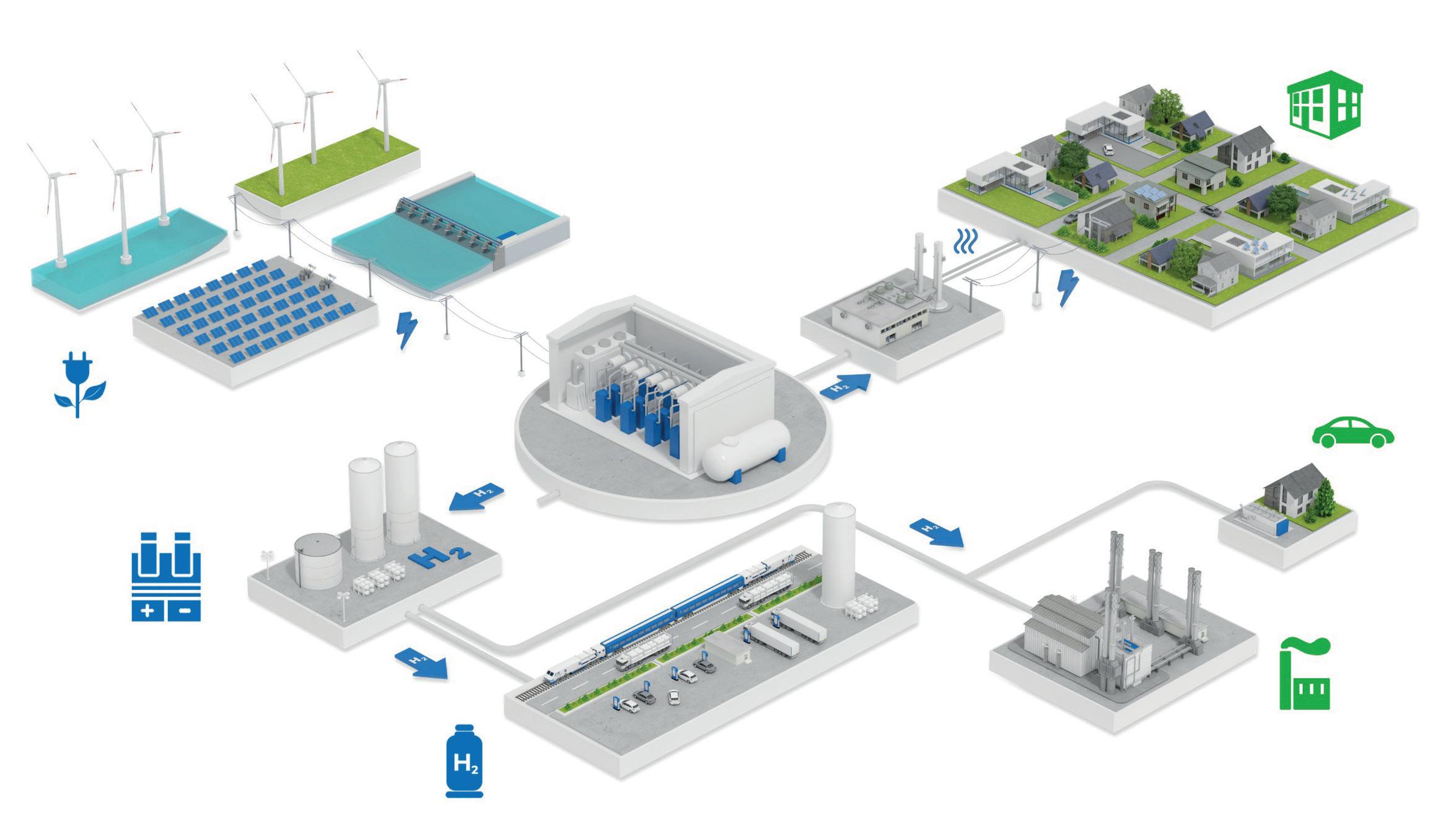
Best practice for all industries
To create a common basis for evaluation, TÜV SÜD has developed a test standard – the so-called P-003 – in cooperation with component manufacturers. For this purpose, existing standards were consulted: among others, ISO/TR 15916 for basic considerations for the safety of hydrogen systems; ASME B31.12 for requirements for hydrogen piping and pipelines; and ANSI/CSA CHMC-1-2014 for the material compatibility of metals in compressed hydrogen applications. Currently, the certification only considers material resistance to compressed hydrogen. This is used in the automotive sector – for hydrogen pipes in fuel cell
62 Spring 2023 GlobalHydrogenReview.com
Figure 1. The path of green hydrogen production towards its future application in various sectors.
vehicles for example – as well as in the stationary sector, such as for transport in pipelines or for high-pressure components in storage tanks.
Whether a material is hydrogen-resistant depends on its type, microstructure, and area of application, as well as on the gas composition of the hydrogen that acts on it. The mode of operation is also decisive for its performance: what stress, pressure or temperature is it exposed to? For this reason, general certification is not possible for a material or component. Rather, certification is conducted on an application-specific basis within the framework of defined boundary conditions.
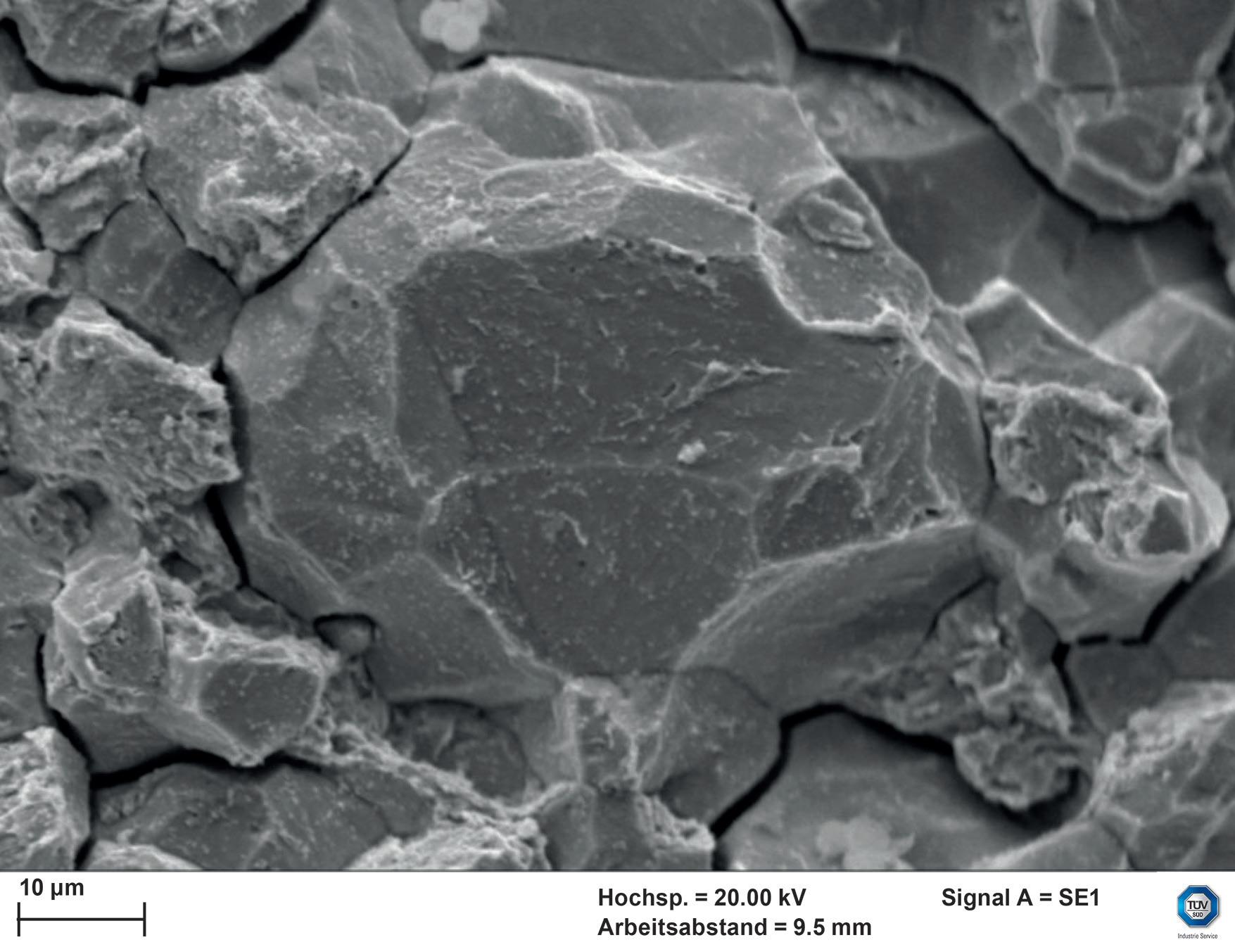
Different test approaches
The first step as part of a qualification of the material resistance to compressed hydrogen in accordance with P-003 is based on a document review. This shows whether there are already reliable findings or whether material tests are necessary. These can be carried out in TÜV SÜD’s own or partner laboratories. In the case of components, all materials that come into contact with hydrogen must provide proof of compatibility.
The choice of evaluation approach depends on the type of material and the area of application, i.e. to prove toughness, the experts perform tensile tests under compressed hydrogen by means of the so-called ‘Slow Strain Rate Tensile Test’. Sometimes it is necessary to evaluate the fracture toughness with fracture mechanics tests, for example. With the pressure cycle test on the complete component, experts can evaluate the service life under realistic loads. During annual audits, TÜV SÜD also ensures that the company still complies with the certified processes that guarantee material compatibility.
Hydrogen-readiness at system level: power plants
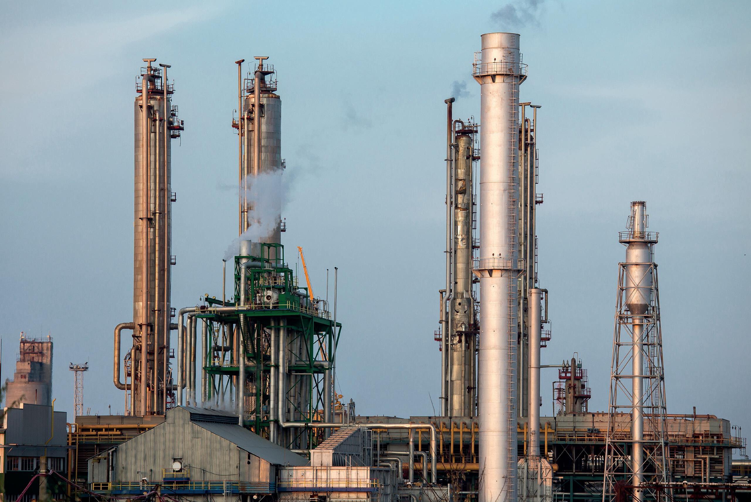
In the future, combined cycle power plants will also run partly or completely on hydrogen. For this reason, operators are already being asked to prepare for the changeover. However, a precise guideline of the requirements to be met has not yet been defined by law. To support original equipment manufacturers (OEMs), plant constructors, and operators in the energy transition, TÜV SÜD has developed a guideline together with Siemens Energy. This sets out the requirements for hydrogen-readiness in combined-cycle power plants, and serves as a basis for testing and certification.
The guideline also addresses the question of which systems and components are affected by the switch from natural gas to hydrogen. Additionally, it details what restrictions are placed on new constructions, and the evidence that is required, and covers the three most important phases along the life cycle: the bidding phase, the realisation phase for initial operation with natural gas, and the transition phase from natural gas to hydrogen. The guideline is currently being successfully applied across several projects.
Making sustainability safe
With P-003, TÜV SÜD has created a testing and certification basis for materials and components regarding their resistance to compressed hydrogen. The new test standard can be used in a wide range of applications, regardless of the industry.
Experts always evaluate and certify the compatibility in relation to the respective application, and highlight the possibilities and application limits of the materials and components. Currently, the focus is on metals, but an extension to include plastics is being planned. For manufacturers and operators, the certification provides a secure framework in legal, economic and safety terms, and promotes confidence in sustainable technologies, as green hydrogen produced using renewable energies significantly reduces emissions from energy-intensive industries.
Register at www.worldfertilizer.com Global publication A global industry requires a global publication Global publication A global industry requires a global publication Register for free at www.worldfertilizer.com For in-depth coverage of the global fertilizer sector
Figure 2. Brittle fracture: sudden material failure under the influence of hydrogen.
Hydrogen has been part of the process industry’s chemical catalogue since well before industrial chemist Fritz Haber met chemical engineer Carl Bosch in the early 1900s and developed the ammonia process. Today, the focus on hydrogen extends well beyond the process industry and into almost every aspect of our lives – from transport to power to heating. All of this activity is being driven by society’s need to reduce greenhouse gas (GHG) emissions emanating from fossil fuels.
However, hydrogen is not the global panacea that people might think. Hydrogen production and delivery to point of use is not a simple undertaking; producing cost-effective hydrogen safely, with minimal impact on the environment, involves an integrated approach

64
Roy Calder, AVEVA, UK, explains the importance of developing digital environments to support the success of hydrogen projects.

65
to planning, engineering and operations, often across multiple sites and operators.
This article looks at the digitally-integrated network approach to a multi-source/multi-end user hydrogen project, from initial planning through engineering and construction, to effective network operations
Hydrogen generation
The current view of hydrogen generation is polarised – either it should be green or blue. However, the specific aspects of each process should be considered before embarking on a project.
Green hydrogen
Generating hydrogen by electrolysis from water is a method known by every high school science student, and with renewable energy – solar and wind – the model is relatively simple in principle. However, today’s electrolysis processes are far more complicated and have developed into a huge industry with the deployment of two main technologies: polymer electrolyte membrane (PEM) and alkali electrolyte membrane (AEM). Each technology has its own pros and cons, and the decision between them is normally based on a high-level modelling study (to be explored later on in this article).
Blue hydrogen
Steam methane reforming (SMR), which results in carbon dioxide (CO2) as a byproduct/emission, has been the de-facto source of industrial hydrogen for over 100 years. While regulatory limits for low-carbon hydrogen are set at 20 g CO2e/MJLHV, the approach to reach this limit on existing and new plants is to capture the CO2 with a carbon capture utilisation and storage (CCUS) system.
Hydrogen project life cycle
To best illustrate how carbon-neutral hydrogen can be manufactured and distributed, this section will consider a major project that incorporates existing hydrogen generation facilities and users, as well as potential new use applications. As with any major capital project, there are vast numbers of variables that make a viable investment case, starting with an estimation of demand and growth to provide the basic project economic envelope.
From the initial decision to go ahead with a project, the complexity often increases as we move through all the phases of a plant life cycle, as illustrated in Figure 1.
Each of these typical project phases may well involve multiple investors, locations and landowners, new/existing facilities, original equipment suppliers, process licensors, utility providers, EPCs and end users.
With this level of complexity, managing both the engineering and operations can be very challenging – at least in a traditional manner. The following project steps can potentially be managed in a connected digital environment.
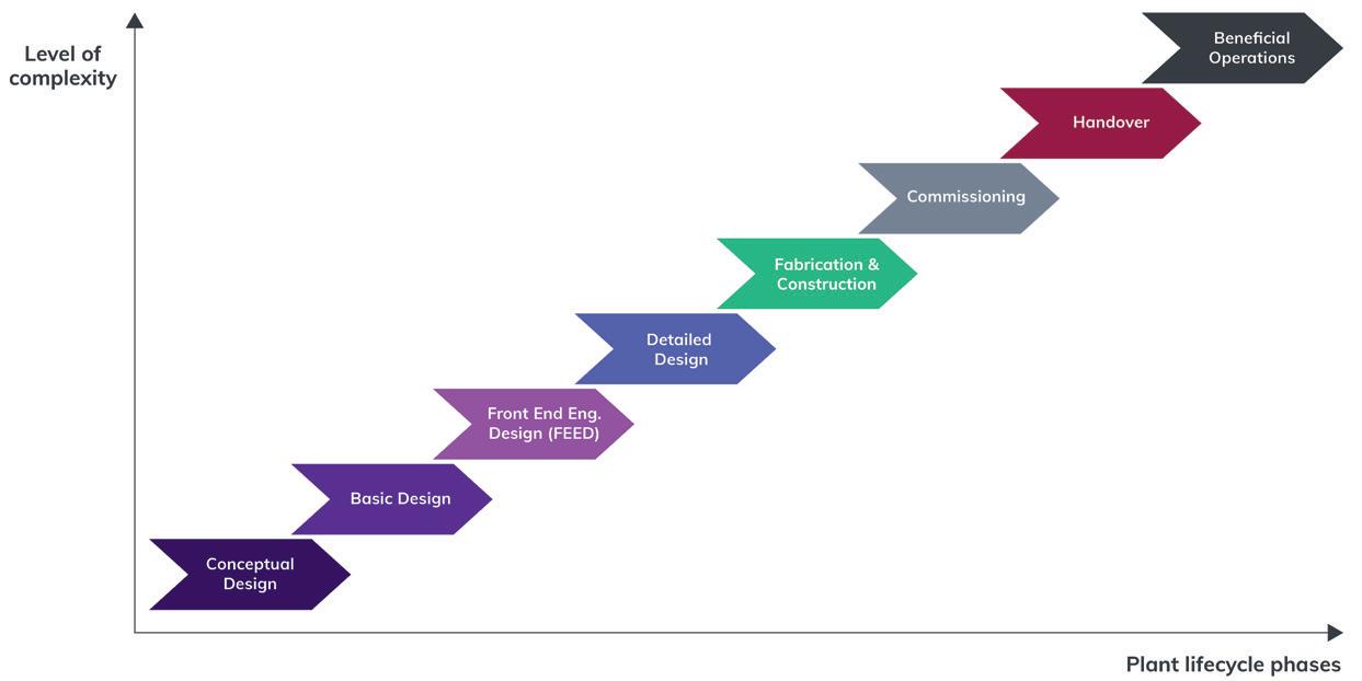
Project inception
Here the adage ‘fail to plan, plan to fail’ is the overarching philosophy. At the heart of this stage is the master planning process, supported by simulation. Master planning is a strategic process whereby a model of the entire hydrogen supply chain is built on a process and geographic basis. This model will consist of some, if not all, of the following units:
� Renewable energy sources.
� Battery storage.
� Water sourcing.
� Water purification.
� Green hydrogen generation.
� Existing grey hydrogen plants.
� Carbon capture plants.
� CO2 pipeline.
� CO2 sequestration.
y New blue hydrogen plants.
y Hydrogen storage.
y Hydrogen compression.
y Hydrogen liquefaction.
y Hydrogen pipeline.
y Ammonia plant.
y Hydrogen distribution network.
This model is built on a process basis but with specific economic parameters for each of the units. The first approach takes a pre-defined hydrogen production specification, and through advanced optimisation algorithms – including artificial intelligence (AI) – produces a set of process specifications for each unit, as well as an overall cost estimation. The main outcome of this model is the best network specification that the investors can initially sign off.
Due to the nature and complexity of the process, the next phase looks to narrow the specifics of the model by optimising the sub models themselves from the process and economic basis. This would involve covering several detailed designs including, but not limited to:
y Renewable energy – define the number of wind turbines, solar panels, and batteries to supply the necessary power to the project, incorporating a detailed climate prediction model.
y Purified water supply – define the location of the water supply, the required piping network, and the purification plant needed
66 Spring 2023 GlobalHydrogenReview.com
Figure 1. Level of complexity of each plant life cycle phase.
to produce the water supply for the electrolyser and steam generation plants.
y Green hydrogen production – define the number and type of electrolysers needed to produce the necessary green hydrogen based on the availability of renewable energy and the overall process/economic model of PEM vs AEM electrolysers.
y Blue hydrogen production – define the size of new blue hydrogen production units as part of the demand side model.
y CCUS – define the capacity and number of CCUS plants to convert existing grey hydrogen plants to blue.
y Hydrogen pipeline, storage and liquefaction – based on the demand side model, the basic sizing of these items is more closely defined and costed.
The final phase is to reintegrate these models into the overall master model and reoptimise it in terms of both the process units and the location. The models must validate whether wind and solar farms are in the correct location, and whether the sites and electrical distribution network are economically-viable. Similarly, with the blue hydrogen units (new units and grey units converted), the model must optimise the number of CCUS plants needed, and where they should be located in relation to the utilisation and/or sequestration sites.
Once these steps are complete and investors have signed off, the engineering phases can begin.
Design, construction, commissioning and handover
Such a project involves multiple parties, working in a tightly coordinated manner. Services range from engineering, fabrication and construction, including disciplines such as civil, process, instrumentation, mechanical, electrical and automation all working towards a common goal. However, there are added complexities:
y Wind and solar farm construction.
y Power delivery to the process plants and battery storage.
y Pipeline provision for hydrogen to its point of use.
y Pipelines for CO2 to where it can be used and/or sequestrated.
Moreover, original equipment manufacturers (OEMs) for the wind turbines, solar panels, electrolysers and process compressors also need to be involved without resulting in added project risk, cost overruns, and schedule slippage.
While this complexity is not unknown in the process industry, the way in which this can be best mitigated in practice is to ensure that everyone works together in a single project digital environment.
A common set of engineering software tools, covering simulation, process flow diagram (PFD)/piping and instrumentation diagram (P&ID), data sheets, line lists, electrical and
instrumentation feeding into a common 3D model, can be hosted on the cloud and utilised by all parties. By combining this with an integrated information management structure, operators can ensure that as engineering data is generated and published, it is available to all users, therefore eliminating the ‘physical’ passing of data with the inherent errors. This digital approach improves efficiency for everyone involved, reducing the schedule and overall engineering cost. The construction phase can also be carried out using a similar single cloud environment with corresponding improvements.
With designs predominantly built on simulation, these models provide the foundation for training for both panel and field operators, where integrated exercises can be carried out well in advance of the actual plant start-up. This approach provides significant improvements to safety and efficiency.
Integrated network operations
Multiple sites feeding multiple clients, each with differing requirements as well as a somewhat unpredictable energy source, can be a challenge to manage.
While the control of all facilities (wind and solar farms, water treatment plants, electrolysers, steam reformers, carbon capture plants, electrical supply, and pipelines) can be managed locally, the real issue is the management of the entire network.
Much has been written about enterprise visualisation and centralised control rooms, but the focus has primarily been on control rather than managing the enterprise. For a hydrogen network, visualisation is only part of the story. It must go beyond the single pane of glass view and be closely aligned with all the necessary tools to cover the elements listed in Figure 2.
The management of multiple process plants can be achieved by a well-structured Production Management System (PMS). The key to ensuring that everything works
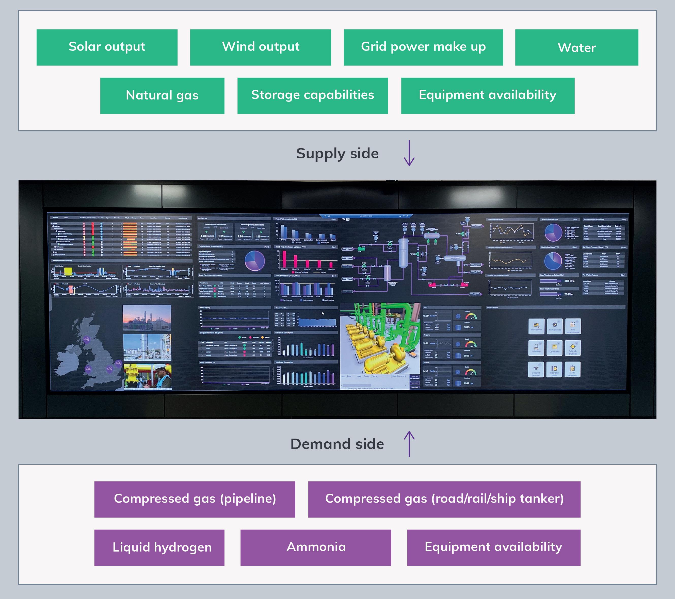
Spring 2023 67 GlobalHydrogenReview.com
Figure 2. Visualisation and management of a complex integrated network.
together optimally is to make certain that the data from all aspects of the network is always available in a format that is suitable for seamless operations. A key approach is to use the power of the cloud to bring together data from the process units with the necessary production planning data from the end user community. While there are many process/business routes to consider here, one is how wind and solar energy becomes hydrogen that is used to power a fuel cell vehicle, and the data that is needed to manage it, as illustrated in Figure 3.
While the demand side is similar to a regular petrol station, the supply side is not as simple or predictable. To ensure the required supply, the demand side data must be seamlessly available to the central operations control. This is achieved by using local data collection equipment, edge equipped, linked to the cloud, and made available to the master PMS model.
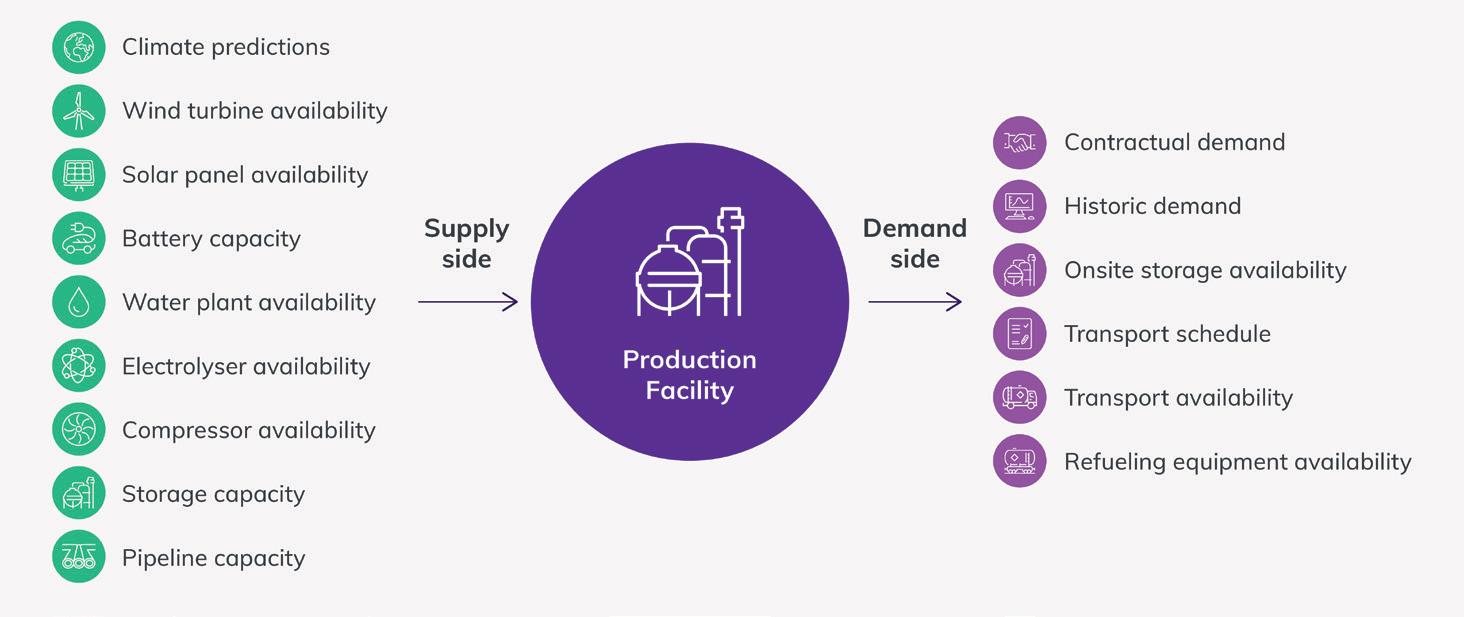
On the supply side, the master PMS maintains a continuous hydrogen generation model using an end-to-end simulation model running with real-time data. The simulation runs against a climate prediction model that can accurately predict the available green hydrogen output. If a shortfall in green hydrogen output is identified, blue hydrogen sources are used instead, with capacity also monitored through the PMS model.
Two common concerns are equipment availability and overall safety. Availability is critical, as these systems are integral and strategic to industrial and commercial operations, including possibly adding hydrogen to natural gas networks. E-machine learning tools can ensure that potential equipment failures are identified early, and addressed
quickly. The predictive analytics generated to minimise downtime are also crucial.
The benefits of the life cycle approach
While complex projects are customary in the process industry, this approach not only relies upon strong project management, but also on having an integrated engineering environment that remains ‘live’ once the network is handed over to operations. Easy access to the engineering data means that operations can work more effectively, providing an economic optimum for both investors and clients.
However, the life cycle approach also provides direct financial benefits beyond the engineering, fabrication, construction, commissioning and handover phase of a project. These can be highlighted as follows, and seen in Figure 4:
y Engineering phase:
� 15% on costs.
� 10 – 15% on schedule.
y Construction phase:
� 15% on costs.
� 5 – 10% on schedule.
y Start-up and commissioning phase:
� 15% improvement on schedule.
y Operations:
20% on operational efficiency.
y Project break-even point:
7% improvement.
Having benefits at all phases of the project that together deliver improvement in the break-even point and hence on the net present value (NPV) calculation for investors is significant, especially when there is no overhead cost as the tools involved are already in use within the project community.
Conclusion
As companies and governments continue to invest in order to meet their net zero commitments, the number of hydrogen projects, in all its varieties, will continue to grow. Joint venture (JV) and collaborative projects will become increasingly prevalent but will have to be managed carefully in order to ensure that all parties are capable of working together effectively, in a digital environment rather than in siloes. The benefits of this approach for investors, in terms of time and cost, are evident.
By developing an integrated life cycle approach from the outset, owner operators can ensure that the engineering and construction phases are delivered as swiftly as possible while minimising risk and cost overruns. In tandem, the project will also deliver an overall operational data infrastructure that supports OPEX optimisation, and in turn improves the overall time to break-even.
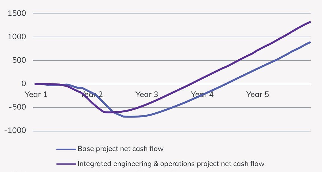
68 Spring 2023 GlobalHydrogenReview.com
Figure 4. Improving project cash flow.
Figure 3. Data required to power a fuel cell vehicle with hydrogen.
To ensure the safe use of hydrogen filling stations, special safety regulations must also be observed in order to protect against the risk of explosion, fire and lightning. The filling stations must be checked and renewed at regular intervals to guarantee a safe refuelling experience.
Digital data collection and analysis for comprehensive monitoring
Through the digitisation of various components in a hydrogen filling station, and the intelligent monitoring of the system, predictions can be made about the stress on the material and the processes in the filling station, enabling constant availability.
The components are networked with each other and mapped online in a digital twin. The data collected covers two categories. Process data (metric data) measures analog values such as storage tank pressure, temperature or gas concentration, as well
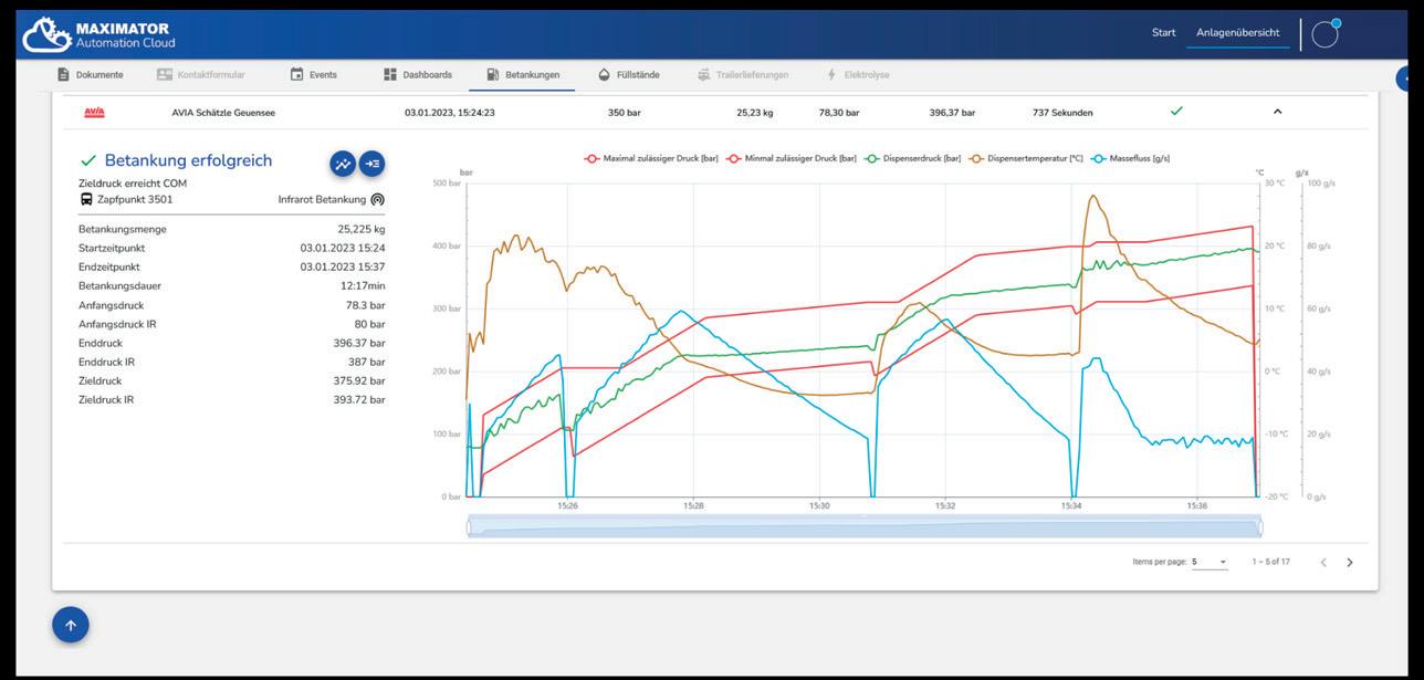
as digital values such as valve positions, initiators, and statistical values such as operating hours. In addition to the metric data, the hydrogen filling station also records error and warning messages, machine events, user actions, refuelling and trailer deliveries – so-called ‘event data’.
The measured values provide information about the status of each individual system and communicate this to the manufacturer and operator via digital interfaces. If necessary, immediate action can then be taken. The networking of all of a providers’ gas stations, and the associated large data set, makes it possible to collect general statistics on frequent sources of error, energy efficiency, and system performance.
Digitisation increases security, efficiency and availability
The high loads on the components in the high-pressure accumulators require regular maintenance or the replacement of stressed materials. Extensive data collection shows how long certain components have been in operation, and when a change makes sense – among other things. This also makes it easy to ensure the operational safety of the systems, which requires regular component testing.
As maintenance is always associated with system downtime, peak times can be determined when data is available during the periods in which fuel is most frequently used. Component replacement can then be planned at a time of low refuelling. This reduces system downtime and income loss for the operator.
In addition to planned downtime, unforeseeable events also cause the hydrogen filling station to fail. If a system stops due to an error, this is registered and the filling station sends a message immediately. This happens if the pressure or temperature drops in one of the high-pressure accumulators, or if a part of the system freezes in winter when temperatures are well below freezing for long periods of time. Operators or manufacturers are informed immediately via the connection to a digital interface, and can analyse the error more precisely and react immediately. The hydrogen filling stations are almost always operational, and can be used by vehicle owners.
Information on fill levels shows how often a system has been refuelled. From this it can be concluded how long the existing hydrogen will last and when the storage tanks must be refilled. Observed over a longer period, operators can automate refuelling, which saves time while guaranteeing continuous operation of the filling station. If a system is started up particularly frequently, operators can consider expanding it with additional pumps and storage units to cover the demand.
70 Spring 2023 GlobalHydrogenReview.com
Figure 1. Analysis of a refuelling.
Figure 2. Cloud dashboard with monthly overview.
Figure 3. Hydrogen filling station map with live data of the installations.
Software updates can also be made in a decentralised way across systems with the help of digitisation. This increases the efficiency of individual components, which then become even more precise. The decentralised control of the hydrogen filling stations plays an important role, especially around system safety, as they must meet special requirements –especially regarding explosion risk. If there is a leak somewhere inside the gas station, components can be switched off via the digital twin, and localities can be sealed off. This prevents hydrogen from escaping.
Digital connection and networked interfaces enable access from anywhere
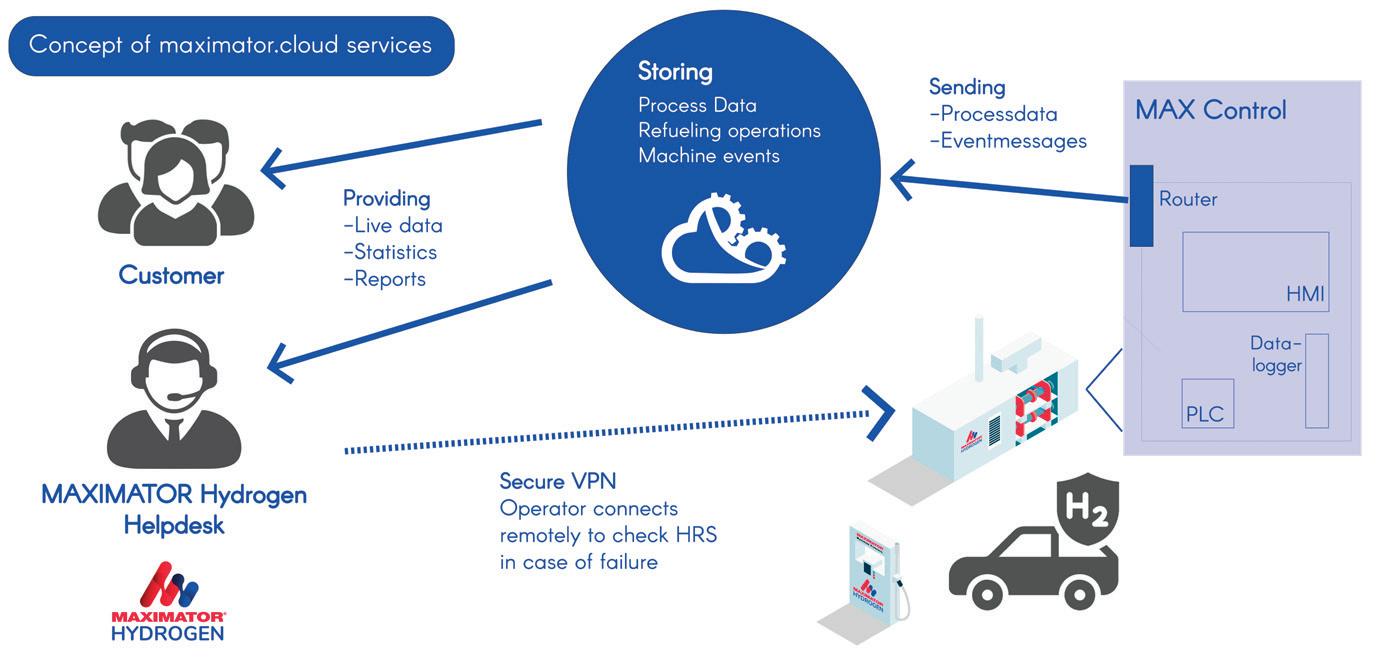
All process data comes together in the controller, where it is picked up by a data logger and distributed. The way in which the systems are networked varies depending on the filling station manufacturer. Uploading the data to a digital interface ensures access from anywhere in the world, and thus a fast response.
Maximator Hydrogen GmbH has developed a system in which everything comes together in the Automation Cloud. From there, the collected data is made available in an information pool for customers. Via access to a web interface, the user receives a personalised dashboard in which the information is presented graphically and statistically. Error messages and machine events are also displayed. In the future, the computerised maintenance management system (CMMS), which informs the customer of planned maintenance and service calls, will also be mapped in the cloud.
The cloud also transmits error messages and other event data to the company’s help desk, which can react immediately, commence analysis and, in coordination with the operator, initiate measures to rectify the error.
In addition to availability in the cloud, a data interface (Web API) enables integration into the customer’s existing systems, providing them with a compact overview without having to switch applications. It is also possible to organise the subsequent delivery of hydrogen. If the levels in the system drop, this triggers an automatic delivery of a new charge.
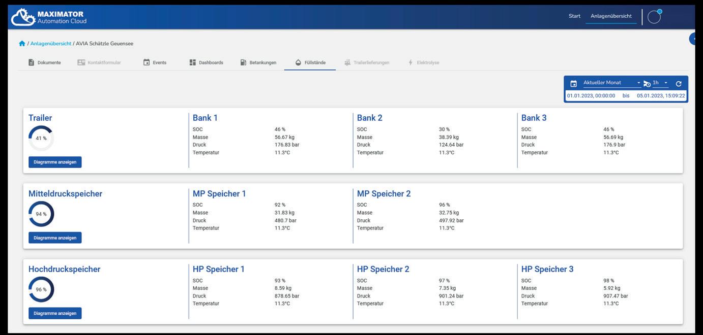
Data-based predictions prevent failures
It is also possible to provide a forecast based on the previously-collected data from the system, which indicates how many vehicles are currently being refuelled, and what fill level the vehicle can reach at the start of refuelling. This forecast is completed by an indication of the waiting time, which shows when the next refuelling is possible. The vehicle owner is informed of this via a display on the petrol pump.
Maximator Hydrogen is currently working on predictive maintenance. Artificial intelligence (AI) is intended to help predict the failure of individual components, or the system. The developers are currently feeding their algorithms with the available data to generate a pattern and design a warning system.
Additionally, platforms such as h2.live and hrs-map.eu receive data on filling levels and system availability, which increases transparency for vehicle owners. This is essential, especially with a very small network such as in Germany, to enable uninterrupted movement.
Digitisation and hydrogen go hand-in-hand
Digitisation plays a crucial role in establishing hydrogen as an energy source in business, industry and transport. Innovative and digital technologies are helping to make filling stations safer, more efficient and permanently available, and not just by using gas as a power source. Technologies such as AI, blockchain or digital twins also support the production or processing of hydrogen, making it available more cheaply, quickly, and across the board, thus contributing to the prevention of global warming.
Reference
1. ‘Carbon dioxide emissions’, German Environment Agency, (21 March 2022), https://www.umweltbundesamt.de/daten/ klima/treibhausgas-emissionen-in-deutschland/kohlendioxidemissionen#kohlendioxid-emissionen-2021
Spring 2023 71 GlobalHydrogenReview.com
Figure 4. Fill level of the storage tanks of a hydrogen filling station.
Figure 5. Concept: Maximator Automation Cloud.

72
Supplier selection is a crucial process for any business, as it can significantly impact the efficiency and effectiveness of the supply chain. Choosing the right supplier can lead to cost savings, improved quality, and increased competitiveness. On the other hand, making the wrong choice can result in delays, defects, and financial losses.
Data science can be an invaluable tool for supplier selection, as it allows for the analysis and evaluation of large amounts of data in a systematic and objective manner. By using data science techniques, businesses can analyse and compare various suppliers based on different criteria, such as cost, quality, delivery performance, and innovation. One way that data science can help with supplier selection is by providing a comprehensive and up-to-date database of suppliers in the hydrogen

value chain. This database can classify companies according to their product portfolios, allowing businesses to easily find and compare suppliers that offer the products and services that they need. Delphi Data Labs has developed such a green hydrogen value chain model. Figure 1 showcases part of this hydrogen model.
If a business is looking for a supplier of hydrogen electrolysers, it can use the database to identify all companies in the hydrogen value chain that offer electrolysers. The business can then compare these companies based on various criteria, such as installed base, types of electrolysers, and manufacturing capacities. By using data science techniques, businesses can analyse and compare the different options in a systematic and objective manner, reducing the risk of making a poor supplier selection.
73
Lukas Strohmeier, Delphi Data Labs GmbH, Austria, explains how big data helps companies to identify the right customers, partners or suppliers in the emerging green hydrogen economy.
In addition to providing a comprehensive database of suppliers, data science can also help businesses to analyse and evaluate the performance of different suppliers. By tracking and analysing data on factors such as delivery times, quality and cost, businesses can obtain a better understanding of which suppliers are meeting their needs, and which are not.
Data science can also be used to track and analyse delivery times for different suppliers. By analysing this data, the suppliers that consistently meet delivery deadlines and those that do not can be identified. This information can be used to deduce which suppliers are the most reliable, and which may need to be replaced.
In addition to analysing performance data, advanced analytics can also be used to assess the innovation and competitiveness of different suppliers. By analysing data on new product development, patents and market trends, businesses can obtain a better understanding of which suppliers are staying ahead of the curve, and which are falling behind. This information can be used to identify those suppliers that are the most innovative and that may need to be replaced.
Overall, data science can be a powerful tool for supplier selection, as it allows businesses to analyse and compare a wide range of suppliers in a systematic and objective manner. By providing a comprehensive database of suppliers and analysing performance data, informed decisions can be made about which suppliers to work with, reducing the risk of making poor supplier selection decisions.
The development of a value chain database in the field of mechanical engineering requires a significant amount of time due to the complexity of the projects, which often involve multiple levels of suppliers and sub-suppliers. These projects are typically large in scope, and require the coordination of a number of stakeholders.
The following steps should be taken into consideration when building a value chain model for the green hydrogen industry:
y Identify the activities involved in producing green hydrogen. These might include things such as sourcing renewable energy to power the electrolysis process, designing and building electrolysers, transporting and storing the hydrogen, and marketing and selling the hydrogen to customers.
y Determine the value that each activity adds to the production of green hydrogen. For example, the electrolysis process adds value by converting renewable energy into hydrogen gas, while transportation and storage add value by making it possible to deliver the hydrogen to customers.
y Organise the activities into a flow chart or diagram. This will help to visualise the relationships between different activities and understand how they fit together to create value for the customer. Figure 2 demonstrates the taxonomy of Delphi Data Labs.
y Document the value chain model in a database. This can be achieved by using a spreadsheet, database software, or other tools. It is important to include information about each activity, including its role in the value chain, the value it adds, and any resources or inputs it requires.
y Use the value chain model database to identify opportunities for improving efficiency, reducing costs, or adding value. For example, operators might look for ways to optimise the electrolysis process in order to improve efficiency, or to develop new technologies for storing and transporting hydrogen.
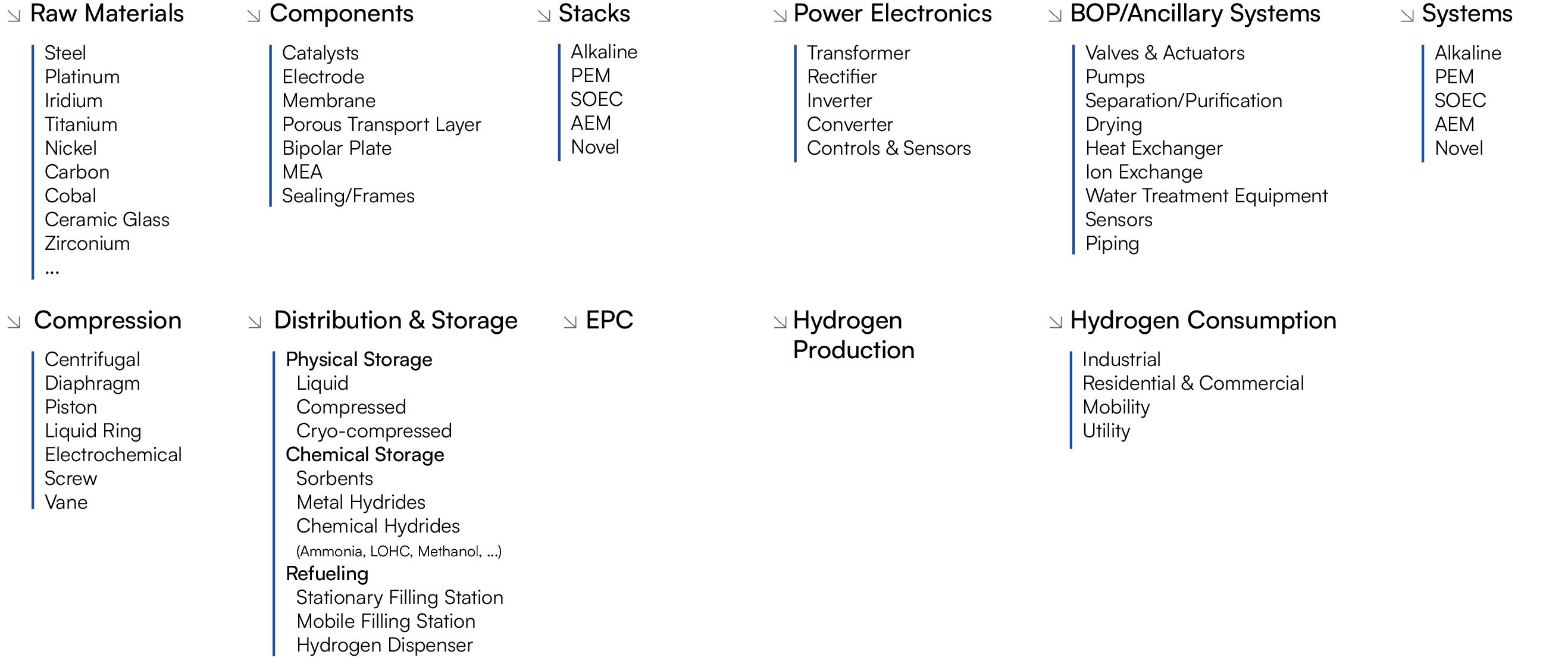
y Update the value chain model database regularly. As the green hydrogen industry evolves and changes, be sure to update the database to reflect any new developments or innovations. This will help with staying on top of trends and adapting to changing market conditions.
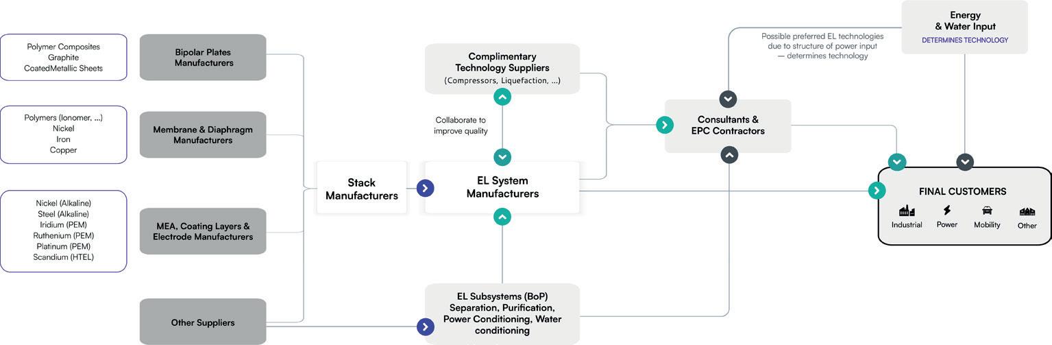
74 Spring 2023 GlobalHydrogenReview.com
Figure 1. Electrolysis value chain model.
Figure 2. Sample of vertical depth of green hydrogen value chain model.
Case study
Delphi Data Labs’ ‘H2-value-chain-model’ helped a component manufacturer to identify potential customers in the hydrogen value chain. The manufacturer offers materials for electrolysers and fuel cells, and was looking to expand its customer base.

The model is the basis of all the market analysis activities of Delphi Data Labs. It assigns thousands of companies to its relevant offerings in the green hydrogen value chain.

By using the H2-value-chain-model, the component manufacturer was able to efficiently and effectively identify potential customers and make informed decisions about which companies to approach. As a result, the component manufacturer expanded its customer base and increased its revenue.
In total, the client was provided with over 150 potential clients in the electrolyser segment, and over 80 companies active in the fuel cell space. The action list included relevant information such as country of origin, homepage, and size of the targets.


As an add-on, a detailed analysis of each company was acquired. For some core technologies, such as hydrogen generation technologies (electrolysers, pyrolysis/gasification, SMR), or fuel cells, Delphi Data Labs offers a dynamic scoring model. Currently, the scoring model analyses all companies in seven dimensions:
y Financials.
y Market share.
y Manufacturing capacities and planned expansions.
y Partner network.
y Global set-up.
World Pipelines

y Technology.
y Strategy.
This addition helped the customer to select the most promising targets out of the longlist. As the client wants to focus its initial business developing activities on companies that already have a successful commercial track record in the electrolysis slide, the scoring model instantly identified the relevant electrolyser manufacturers and excluded all start-ups and new market entrants.
The H2-value-chain-model proved to be a valuable tool for the component manufacturer, as it allowed for the easy and accurate identification of potential customers, and for informed decisions to be made about which companies to approach. The ability to classify companies according to their offerings in the hydrogen value chain allowed the component manufacturer to target efforts and resources more effectively, leading to increased business success.
Conclusion
Overall, the H2-value-chain-model developed by Delphi Data Labs can be a valuable tool for businesses looking to optimise the supplier selection process. By providing a comprehensive database of suppliers and analysing performance data, businesses can make informed decisions about which suppliers to work with, reducing the risk of making poor supplier selection decisions. The use of data science techniques ensures that the analysis is systematic and objective, providing businesses with the information needed to make informed decisions.
Visit our website today www.worldpipelines.com The home for the latest pipeline news, analysis, comment and events
BASF technology selected for blue hydrogen and ammonia project in Japan
BASF Japan Ltd has announced that the high-pressure regenerative carbon dioxide (CO2) capture technology HiPACT®, co-developed by BASF and its engineering partner JGC Corp., will be used by INPEX Corp. in its Kashiwazaki clean hydrogen/ammonia project.
This is Japan’s first demonstration project for the production of blue hydrogen/ammonia from domestically-produced natural gas; the consistent implementation of carbon capture, utilisation and storage (CCUS) in domestic depleted gas fields; and the use of hydrogen for power generation and ammonia production. The project is funded by the Japanese governmental organisation, New Energy and Industrial Technology Development Organization (NEDO).
The technology will be applied to efficiently capture and recover CO2 in the process gas from a hydrogen production facility using domestic natural gas as feedstock. The production facility, which is under construction by JGC Japan Corp., is expected to start up in 2025.
Enagás, GRTgaz, REN and Teréga to boost transformation of the gas grid into hydrogen
The Spanish (Enagás), French (GRTgaz and Teréga) and Portuguese (REN) Transmission System Operators (TSOs) have signed the initiative ‘Green2TSO’, which is aimed at transforming the gas grid into a hydrogen grid.
The Green2TSO project is aligned with the European Commission’s initiatives – the Green Deal, Fit for 55 and REPowerEU – underlining the role of European TSOs to become carriers of hydrogen as an efficient, safe and clean energy vector. Through Green2TSO, the consortium will carry out pilot projects, technology tests and other tasks, in order to accelerate the transformation of the natural gas grid.
The technology fields to be prioritised will be technologies for development of hydrogen detection and measurement systems; compression and aboveground storage; and alternatives for coating and cleaning of pipelines.
One project in the field of hydrogen detection and measurement led by Green2TSO promoters, called ‘Green2TSO OPHTYCS’, has already been chosen by the European Commission to be co-funded.
PowerCell secures hydrogen fuel cell order for Norwegian ferries
Hydrogen fuel cell supplier, PowerCell, has signed an agreement to deliver hydrogen fuel cells to two ships operating on Norway’s longest ferry route, representing a significant milestone for the shipping industry’s energy transition. The order, which was secured after a thorough tender process, has a value of €19.2 million, and represents the largest non-combustion fuel propulsion project to date in the global marine industry.
PowerCell will work with SEAM to deliver the solution, who will be responsible for the electrical installations on the ferries. Final delivery is to take place in 4Q24. Torghatten Nord and PowerCell also intend to enter into a long-term service agreement.
PowerCell will deliver its PowerCellution Marine System 200 to two vessels owned and operated by Norwegian transport group, Torghatten Nord, enabling the ferries to produce approximately 6 MW of power each.
The ferries, which will predominantly be powered by green hydrogen, are expected to reduce their combined CO2 emissions by 26 500 tpy.
Siemens Energy to supply electrolysers to new e-fuels facility in Texas
HIF Global and Siemens Energy have reached an agreement that will allow Siemens Energy to expand its electrolyser manufacturing capacity beyond its previously announced plans. This agreement will assist HIF Global in obtaining sufficient capacity for the HIF Matagorda e-fuels facility. The electrolysers will aggregate an expected capacity of approximately 1.8 GW to support approximately 300 000 tpy of green hydrogen production.
The facility will be the first world-scale e-fuels facility, located in Matagorda County, Texas, US. The two companies are engaged in FEED for 1.8 GW of Silyzer 300 polymer electrolyte membrane (PEM) electrolysers that will use renewable energy to separate hydrogen from water, resulting in approximately 300 000 tpy of hydrogen. The green hydrogen will be utilised together with recycled carbon dioxide to produce carbon-neutral e-fuels, which are chemically equivalent to fuels used today and can therefore be dropped into existing engines without the requirement for any modifications.
76 Spring 2023 GlobalHydrogenReview.com
Westwood: lack of certainty risks stymieing the UK’s hydrogen pipeline
New research by Westwood Global Energy Group has highlighted a bountiful pipeline for the UK hydrogen sector, with 17 GW of capacity projected to come online by 2030. However, only a small number of demonstration-sized green hydrogen projects have reached final investment decision (FID) thus far.
Following Russia’s invasion of Ukraine, the UK government doubled its original 5 GW low-carbon hydrogen production, and by taking a two-pronged approach and supporting both blue and green hydrogen, the industry is setting itself up for success. However, according to Westwood’s analysis, political instability; a lack of government clarity around future support; incomplete definitions; and the pending approval of business models could stunt growth potential.
Joyce Grigorey, Director of Hydrogen, Westwood, said: “Global competition is quickly heating up and any delay in the government’s steer could have adverse consequences for the UK’s hydrogen ambitions should investors believe they can gain higher returns elsewhere”.
Page Number Advertiser 23 AMETEK Process Instruments 13 Black & Veatch 51 Burckhardt Compression 09 Chart Industries 17 Elliott Group 43 Endress+Hauser 52 Energy Global 14 & 55 Global Hydrogen Review 19 Hydrocarbon Engineering OFC & 41 H2scan IFC Mokveld Valves BV 25 Oliver Valves Ltd 59 Palladian Publications 29 ROSEN Group 07 Shell Catalysts & Technologies 02 Topsoe 63 World Fertilizer 75 World Pipelines
For the latest hydrogen news, click here and follow us on social media www.globalhydrogenreview.com @HydrogenReview Global Hydrogen Review @Hydrogen_Review

www.globalhydrogenreview.com Register for free: For more information on advertising and editorial opportunities please contact: callum.oreilly@globalhydrogenreview.com chris.atkin@globalhydrogenreview.com sophie.birss@globalhydrogenreview.com We hope you enjoyed the Spring 2023 issue of Global Hydrogen Review
