


❖❖ Rust Formationandprevention Merryweather FireEngine AmericanLoco CamshaftGrinder THEORIGINALMAGAZINEFORMODELENGINEERS Vol.232No.473922March–4April2024 Joinouronlinecommunity www.model-engineer.co.uk Selfpropelledmachine toroughlyone-thirdscale Theclassic4-4-0as seenontheprairies DIYgrindingmachine


Published
Tel:
2023
Editor: Martin R Evans
MEeditor@mortons co uk
Deputy editor: Diane Carney
Designer: Druck Media Pvt Ltd
Club News: Geoff Theasby
Illustrator: Grahame Chambers
Publisher: Steve O’Hara
CUSTOMER SERVICES
General Queries and Back Issues 01507 529529
Monday-Friday: 8 30am-5pm
Answerphone 24hr
help@classicmagazines co uk
www classicmagazines co uk
ADVERTISING
GROUP HEAD OF INVESTMENT – Lifestyle & Tractor Publications | www talk-media uk
Mason Ponti
mason@talk-media co uk
Investment Manager: Chris Jeffery
By post: Model Engineer advertising, Mortons Media Group Media Centre Morton Way
Horncastle, Lincs LN9 6JR
PUBLISHING
Sales and distribution manager: Carl Smith
Marketing manager: Charlotte Park
Commercial director: Nigel Hole
Publishing director: Dan Savage
SUBSCRIPTION
Full subscription rates (but see page 426 for offer): (12 months, 26 issues, inc post and packing) –UK £128 70 Export rates are also available, UK subscriptions are zero-rated for the purposes of Value Added Tax
Enquiries: subscriptions@mortons co uk
PRINT AND DISTRIBUTIONS
Printed by: William Gibbons & Son, 26 Planetary Road, Willenhall, West Midlands, WV13 3XB
Distribution by: Seymour Distribution Limited, 2 East Poultry Avenue, London EC1A 9PT
EDITORIAL CONTRIBUTION
Accepted photographs and articles will be paid for upon publication Items we cannot use will be returned if accompanied by a stamped addressed envelope and recorded delivery must clearly state so and enclose sufficient postage In common with practice on other periodicals, all material is sent or returned at the contributor’s own risk and neither Model Engineer, the editor, the staff nor Mortons Media Ltd can be held responsible for loss or damage, howsoever caused The opinions expressed in Model Engineer are not necessarily those of the editor or staff This periodical must not, without the written consent of the publishers first being given, be lent, sold, hired out or otherwise disposed of in a mutilated condition or in other unauthorised cover by way of trade or annexed to or as part of any publication or advertising, literary or pictorial manner whatsoever


http://www facebook com/modelengineersworkshop


Vol. 232 No. 4739 22 March – 4 April 2024
428 SMOKE RINGS
News, views and comment on the world of model engineering
429 BRADFORD CHALLENGE
The Bradford Model Engineering Society invites you for an afternoon of speed and fun
430 MERRYWEATHER SELF PROPELLED STEAM FIRE ENGINE
Werner Schleidt finds an old boiler and is inspired to construct a fire engine around it
433 LNER B1 LOCOMOTIVE
Doug Hewson presents a true to scale fiveinch gauge model of Thompson’s B1
436 GRINDING THE TARCUTTA CAMSHAFT
Gerard Dean needs a pair of camshafts for a V12 motorcycle engine so decides to grind them himself
438 RUST FORMATION AND PREVENTION IN THE WORKSHOP
Neil Raine looks at the causes of rust and how it may be prevented
442 THE AMERICAN LOCOMOTIVE
David Rollinson takes a look at the classic and ubiquitous 4-4-0 locomotive.
447 AN ENGINEER’S DAY OUT
Roger Backhouse discovers an ancient water powered grain mill in the Outer Hebrides
450 BUTTERSIDE DOWN
Steve Goodbody returns with fur ther tales


of the trials and tribulations of a model engineer’s life
452 HERCULES – A TWIN CYLINDER COMPOUND ENGINE
Chris Walter describes a condensing marine engine first featured in Model Engineer 100 years ago
456 BUILDING 3020 CORNWALL
IN 5 INCH GAUGE
Jim Clark builds a model of Francis Trevithick’s LNWR 2-2-2 locomotive
460 THE STATIONARY STEAM ENGINE
Ron Fitzgerald tells the story of the development of the stationary steam engine
463 1934 McDONALD TRACTOR
George Punter tackles another tractor construction project
464 POSTBAG
466
Readers’ letters
THE WILLIAMSON ENGINE REVISITED
Ray Griffin discovers a book by Tubal Cain from 1981 and builds the engine described in it
469
THE PERPETUAL DEMISE OF THE MODEL ENGINEER
Luker argues that reports of the death of model engineering are greatly exaggerated
472
CLUB NEWS
Geoff Theasby compiles the latest from model engineering clubs around the world
475
CLUB DIARY
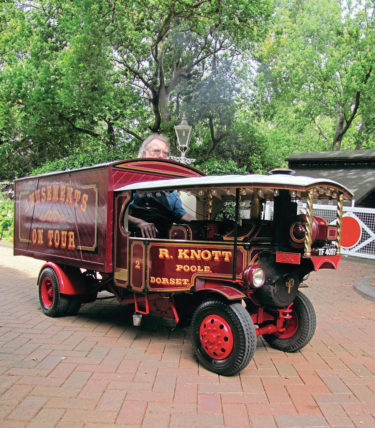
O N T H E C O V E R . . . A Merryweather self
propelled steam


www.model-engineer.co.uk 423
by Mortons Media Group Ltd, Media Centre, Morton Way, Horncastle, Lincs LN9 6JR
01507
Future Events Fax: 01507 371066
529589
Mortons Media ISSN
©
0026-7325 www model-engineer co uk
EDITORIAL
fire
This issue was published on March 22, 2024. The next will be on sale on April 5 2024 Rust Fo ma on and p event on m n e o Merry weather Fire Engine American Loco Camshaft Grinder THE OR G NAL MAGAZINE FOR MODEL ENGINEERS T E R N L M GA O EL EN EE S 2 – 4 0 Join ou o line c mmunity Jo m it www mode -eng nee c k de - g e Self propelled machine to roughly one-third scale The classic 4-4-0 as seen on the prairies DIY gr nd ng mach ne SUBSCRIBE & SAVE UP TO 49% See page 426 for details www.model-engineer.co.uk 452 469
http://twitter com/ modelengineers
engine built by Werner Schleidt (photo Werner Schleidt)

Enjoy 12 months for just £68


Great reasons to subscribe
>> Free UK deliver y to your door or instant download to your digital device
>> S ave money on shop prices
>> Never miss an issue
>> Receive your issue before it goes on sale in the shop
SUBSCRIBE AND SAVE
P R I N T + D I G I TA L D I G I TA L O N LY P R I N T O N LY Q uar terly direc t debit for £19 1 year direc t debit for £68 1 year credit/debit c ard for £74 Q uar terly direc t debit for £22* 1 year direc t debit for £85* 1 year credit/debit c ard for £88* 1 year direc t debit for £50* 1 year credit/debit c ard for £54* *Any digital subscription package includes access to the online archive
classicmagazines.co.uk/ M E D P S 01507 529529 and quote MEDPS Lines are open from 8.30am-5pm weekdays GMT O ffe r e nds D e ce mb e r 31, 2024 Subscriptions will s t ar t w ith the ne x t availab le issue D ire c t D e bit p ay me nt s w ill continue on the agre e d p lan unless you te ll us othe r w ise To v iew the privac y p o lic y for MMG Ltd (pub lishe r of M o de l Engine e r), p lease v isit w w w. mor tons .co.uk /privac y Pl e ase v i s i t w w w.c l ass ic m ag a z i ne s .co.u k / te rm s for fu l l te rm s & con d i t ions . ( 8
Bradford Challenge


 MARTIN EVANS Editor
The Bradford Model Engineering Society invites you to join them in An Afternoon of Speed and Fun
Every year, club members build locomotives that are designed to compete in a time trial around the club’s miniature raised track in Northcliffe Woods, Shipley This has evolved into ‘The Bradford Challenge’ for which, as a local model engineering society/college/school, you are cordially invited to join
 DIANE CARNEY Assistant Editor

Mar tin Evans can be contacted on the mobile number or email below and would be delighted to receive your contributions, in the form of items of correspondence, comment or ar ticles.
07710-192953
MEeditor@mortons.co.uk
We believe that this challenge offers an excellent opportunity for your students/members to design and build a bespoke high-speed locomotive that will compete to see who can circumnavigate the track twice, in the shortest time, whilst staying firmly on the rails
Each locomotive is an excellent project in mechanical, electrical and electronic engineering, which could be part of a student’s curriculum or just a fun model to make
We would also like to attract young engineers to the modelling world We plan, therefore, to run a ‘Junior Section’ for anyone 16 years or younger. To help them get started, we will provide a basic kit of parts, including wheels and an electric motor
For further details and guidelines, please see page 429 For a locomotive’s eye view of our track, please see the video at www youtube com/watch?v=GHcult62ZPY
LOWMEX
As a result of last year’s Lowestoft Model Engineering and Model Making Exhibition (LOWMEX), the Halesworth Model Engineering Society was able to present a cheque for

£521 50 to S O L D (Supporting Our Local Disabled), their designated charity, just before Christmas The photo above (by Julie Williams) shows Peter Williams, Kevin Rackham and Gary Edwards presenting the cheque to Mat Parker and some of Mat’s art and crafts group.
This year’s LOWMEX will take place on the 2nd and 3rd November 2024 again in the Energy Skills Centre, at East Coast College, St Peters Street, Lowestoft, NR32 2NB Entry forms for previous exhibitors were sent out in February If you have not exhibited with them before and would like an entry form, please get in touch
Further information is available www lowmex co uk or contact Kevin Rackham on 01502 583317.
Odd Drill
Graham Astbury writes with the following enquiry
‘Having had some discussions with my fellow club members about twist drills, one member produced the drill as in the photograph It is ¼ inch diameter, with very short flutes, and the arallel inch diameter section above the flutes is about inches long, with a No.1 Morse taper. The point appears to be fourfacet ground and it probably dates from the 1980s or 1990s We were not at all sure as to
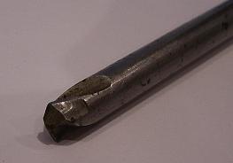
its purpose - clearly it cannot be for drilling deep holes as the flutes do not go u the shank more than about ½ inch We concluded that it might be for drilling steel hollow box sections, so the drill passes through the first side and is then guided to the opposite side by the smooth shank
The four-faceted point would then self-centre and drill the second side This would save marking out the second side, thus avoiding possible errors Does any reader know if this is the purpose of the drill? If not, what is its purpose as it is obviously a non-standard s ecialised long drill
Any ideas gratefully received
Dave Bramwell
Mike Sayers from the Pickering club writes to say ‘I am sorry to have to inform you of the death of Dave Bramwell He died on the 30th of January after losing his fight with oeso hageal cancer
Dave was well known by exhibition visitors for his multitude of jewel like I C engines, most of which were silver and gold medal winners in the 80s and 90s These were often featured on the cover of Model Engineer
‘As well as being a skilled watchmaker and engineer he possessed a wicked sense of humour, his only steam engine featuring a purposely curved cylinder and bent crankshaft
The boiler was constructed from a 2 inch Yorkshire 90 degree elbow with observation windows
‘His wife Doreen would like to thank all his friends who have been such a support ’
Model Engineer 22 March 2024
428
Bradford video
LOWMEX
Bradford Challenge C al
A n A f t e r n o o n o f S p e e d a n d F u n

Adrian Shuttleworth president of the Bradford club, invites all comers.

This event takes place at the Bradford club’s Northcliffe Woods track on June 8th
To give as much opportunity as possible and to cater for all levels of expertise and pockets, we will split the competition into three classes of locomotive:
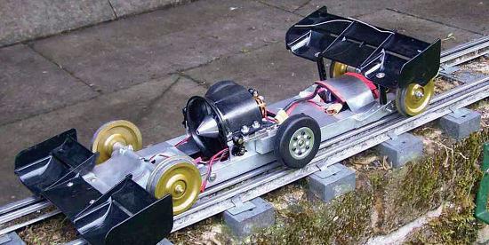
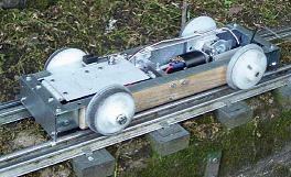
• Ducted fan(s) or Propellers (photo 1)
• Wheel-driven (photo 2)
• ‘All-Comers’ - a class for the innovative or just plain fun locomotive, such as Shaun the Sheep (photo 3)
If you are interested in participating or would like further details, please contact:
Adrian Shuttleworth 07767 375648 or president@ bradfordmes uk or adrian shuttleworth99@gmail com
For more information on the society as a whole, please visit our website or Facebook pages:

www.bradfordmes.uk
@bmesTrains
Facebook: BradfordMES
Guidelines and Rules
The guidelines and rules are simple, thereby ensuring that the vehicles are relatively low cost to build They are:
• The locomotive must have at least two flanged wheels at a gauge of 5 inches (127 mm)
• The video mentioned above gives a good appreciation of the track environment and the track itself, which has a 3½ inch rails within the 5 inch ones
• Have radio-controlled speed control
• Have an effective braking system to bring the locomotive to a complete stop within a reasonable distance of 30 metres – about a quarter of the track length
• Engines using combustible fuels are not permitted!
• The time trial starts from standing, which can be held by the locomotive’s brakes but not by the contestant, at the timing gate.
• To aid timing and identification, each entry should have a suitable, unique name
• The timing system is expected to use a light beam across the track at about 40 mm above the rail height Therefore, to ensure correct detection of the high-speed locomotives, a vertical flag of 50-60 mm height and >20
mm length should be firmly fitted to the front of the locomotive
• The locomotive must complete two laps of the track, then come to a complete stop after passing the timing gate for the second time
• Competitors will be allowed one practice run and two timed runs. Should any locomotive fail to complete a timed run, then that run will still count as one of the two allowed timed runs
• In the ‘All-Comers’ class, the judging will be purely on the amusement value of the entry, be that the locomotive’s construction, propulsion method or message(s) that it portrays The raised track at Northcliffe Woods is configured in such a way that passers-by or spectators are protected from any locomotive that derails and/or leaves the track However, to ensure the safety of the members and public, the Bradford MES organisers can, with due consideration, prohibit the running of a locomotive if it is deemed to be dangerous or unsafe
If anyone would like to check that their locomotive will be acceptable, or simply to do test runs, then they are very welcome to bring it to the track prior to the event. If you’d like to do so, please do not hesitate to get in touch
If you have any queries on the competition, track or rules, please do not hesitate to contact myself or any member on the BMES Committee
Bradford Model Engineering Society
Adrian Shuttleworth –President
429 www.model-engineer.co.uk
Wheel driven competitor.
Competitor with ducted fan.
‘Open’ class
Bradford MES
1 2 3
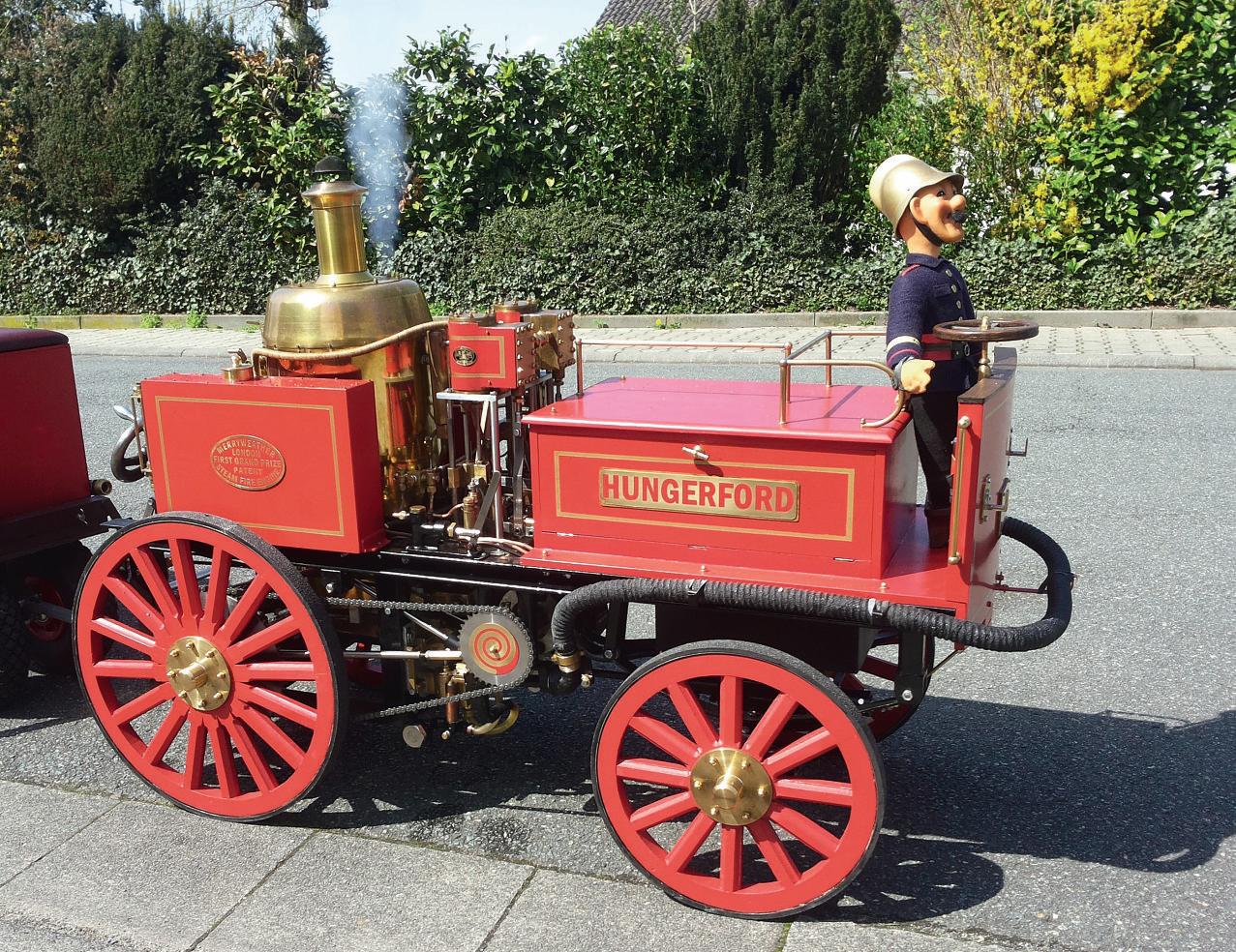
M e r r y w e a t h e r S e l f Pr o p e l l e d r
S t e a m F i r e E n g i n e
PA RT 1
Werner Schleidt
builds a one third scale Merryweather fre engine

Sometimes it’s quite strange how coincidences can lead to a model project Sometime in the summer of 2014, I had the inspiration to look for live steam boilers at a large online auction house in the UK. After some searching I found a few locomotive boilers but, as I didn’t want to bid much, I regularly lost the auctions It has to be said that I already had four five inch steam locomotives at that time but I was really interested in starting something new
One Sunday evening I had the inspiration to search again I found a vertical boiler intended for a quarry locomotive at a reasonable price that expired on Monday morning. I then decided on my pain threshold and bid on it In the evening
after work I saw I had won the auction Now began a phase of searching for prototypes – yes, it is fun to build a project in my mind I soon found a nice prototype and started with the detailed planning But things often turn out differently than you think.
On the last Sunday in September 2014, as every year, I was at a steam meeting Friendly model builders from Zurich came to visit One of them had a large steam tractor with him I was very impressed by the ride That was the point from which I started looking for road vehicles Some time ago I had built a remote-controlled steam fire engine Now it had become clear to me what I wanted to build
After some searching on the internet I decided on a self-
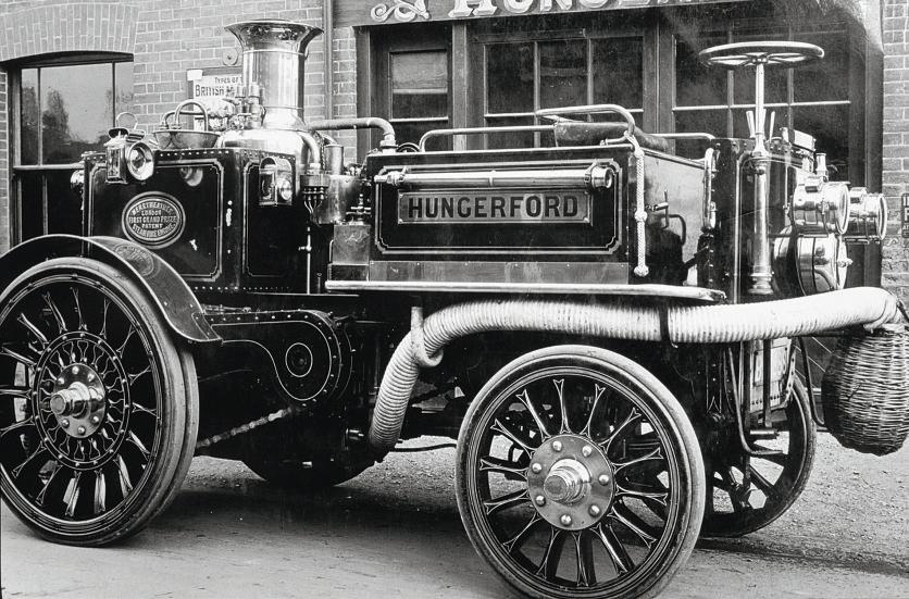
ro elled steam fire engine from Merryweather and Sons
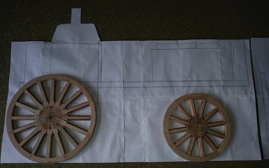
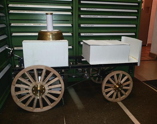
There were some pictures of originals and in a copy of the magazine The Engineer from 1906 I found a two side views and original pictures (photo 1) I then started to draw an overview drawing, taking into account the boiler dimensions and my transport limitations This resulted in a wheel diameter of 400 mm for the rear wheels and 300 mm for the front wheels
For all my models I focus on functionality and don’t aim for museum quality - I’m prepared to make compromises to achieve good operation
In those days, the wheels of even heavy vehicles were usually made of wood Only so-called tropical wheels, for export, were made of metal. I then researched how wagon wheels were made in the past I quickly realised that I was not in a position to imitate this construction method with my own facilities As a model builder you are used to having to think of alternative solutions
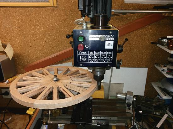
The second problem was the question of how to get a 400 mm diameter turned round Talking to model making colleagues, the solution was to mill round instead of turning As there is only one table milling machine available, this was still a challenge. The material requirements were determined and beech wood was ordered I started with the big wheels First a drawing was made on cardboard I even had to improvise and make the compass big enough to draw it
On the drawing, which was covered with clear plastic, the
430 Model Engineer 22 March 2024
The ‘Dreadnaught’ fre engine 1906
1
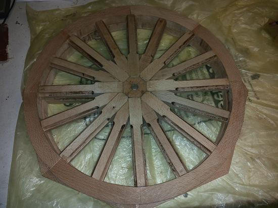
outer rim was built from single segments and glued together as a ring (photo 2) The centre piece for the hub was then made with the sockets for the s o es ach s o e was fitted and marked without glue After everything fitted, the s o es were removed and the edges chamfered to give the wheel a more pleasing appearance
During all the work with the milling machine, the dirt had to be extracted from the wood cutter and the air had to be sucked in to cool it down This was done by vacuum cleaner
The feed was carried out by hand on the inside and outside of the outer ring The maximum depth of the cut was 0 3 mm My rotary table stopped working after a few turns of the crank
Since I was already improvising, a shelf board was used as a support A bolt in the ‘T’-slot plate was
the pivot point A breakfast board was used as a spacer The turning was done by hand (photo 3) That was quite tedious For milling the spokes I could use a self-made feed attachment But 56 spokes times four sides were very time-consuming to machine
I worked on the wheels for a total of 2 5 months (photo 4)
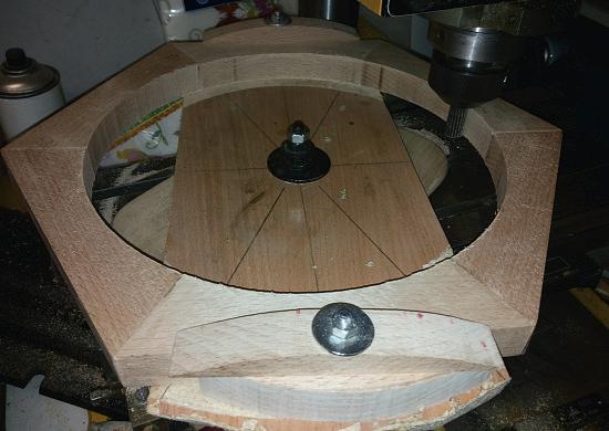
After the shell of the wheels was finished, the general arrangement drawing could be completed (photo 5).
By now it was January 2015 and I compiled a list of materials, as the building season continued until April For the wheels, the hubs were then made, fitted with ball bearings All spokes were additionally fi ed with wooden dowels The circumference of the wheels was laminated with three layers of GRP tape Later, a 1 mm steel strip was glued
On the table as base.
and screwed onto it Yes, the wainwright and the blacksmith were good in the old days but I had to work within my limitations, which did not allow a comparable approach
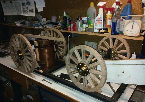
After the wheels were finished, the front a le, the steering knuckle and the suspension were worked
on Everything was built upside down on the table as a reference surface The rear axle was also prepared in this way test fit with the boiler gave a first im ression of the vehicle but one had to rethink a bit, since everything was upside down (photo 6) Since only a few original pictures could be
431 F I R E E N G I N E www.model-engineer.co.uk >>
Wheel on the covered drawing
Wheel milled outside
Overview drawing
Wheel inside milled.
2 3 4 5
6
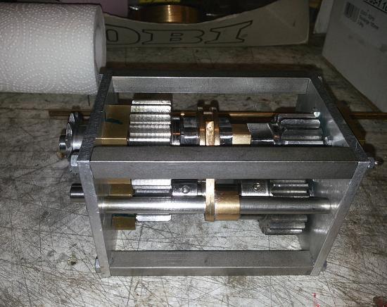
Gearbox.
measured, I had the impression that the fire engine would be too wide The transport vehicle was carefully measured and the trailer was also considered With these measurements a compromise could be found, i e the frame connectors had to be shortened After that, it looked quite coherent
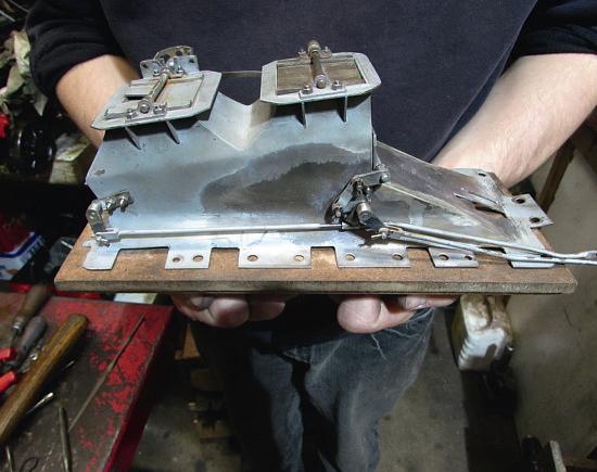
At Easter 2015, I was ready to put the frame on its wheels. The front superstructure and a side tank were glued together from cardboard and a positioning test was carried out (photo 7) This procedure has proven itself in my model projects It is a simple way to get a good overview of whether everything matches the old pictures It was thus also possible to determine better the position
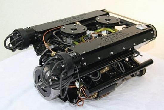
Now it was time to design the drive with chain gear and steam engine But how do you lay out such a drive? In such a case, it makes sense to collect all the known requirements The driving speed should be within the legal limit of 6 km/h I also knew from a colleague that his steam tractor pulled a small car in first gear n estimation resulted in a tractive force of 500 N The drive wheel diameter was also known to be 400 mm The desired steam engine flow rate was min t was also known that the engine should be drivable from approximately 3 bar pressure With all this information, the calculations could now be carried out The chain wheel with 80 teeth mounted on the rear wheel was chosen.
This was also the reason why I decided on this chainring size this was the maximum diameter I can turn on my bigger lathe The calculated gear ratio was divided into the chain ratio visible from the outside and the ratio from the steam engine to the differential
a new chain wheel An overall gear ratio of 10 was chosen for 2nd gear and 22 for 1st gear With this design, it was estimated that the speed would drop under load
With the ratios found, the piston force up to the trailer coupling and the necessary boiler pressures were calculated. It became clear that a design with a piston diameter of approx 40 mm and 60 mm stro e could fit then thought about which construction variant would make sense
In the secondhand section of Maxitrak I found pre-machined gunmetal cylinders that fitted the project exactly It didn’t matter that the piston diameter was 41 7 mm, as I could easily adapt the pistons
of the steering gear and the resulting deflection angles of the intermediate shaft The steering gear consists of a ballbearing trapezoidal threaded spindle, a bronze nut and the bearing housing A pin is screwed to the bronze nut and guided in a slot in the housing Thus, a linear movement is generated from a rotary movement. The pin engages in a slot in the bell crank which is connected to the track rod The advantage is that in the middle the steering reacts directly and towards the steering stop the eight turns of the steering wheel from lock to lock have less effect The trapezoidal threaded spindle and nut were an e ay find, a remnant from the repair of a wooden splitting machine
As it was known from literature studies that the original had problems to drive on steep slopes or was not fast enough on ground level, it was decided to add a manual gearbox with neutral. The neutral gear was needed anyway to pump water when stationary, to feed water into the boiler or to operate the fire engine The gear wheels could be procured cheaply from a remaining stock With a bit of luc , they fitted e actly the number of teeth that was required The gearbox was designed as a sliding sleeve gearbox with neutral in the middle (photo 8)
The first ste was to build the differential myself as a spur gear differential. An inner intuition told me to search on eBay The search found a differential from a cannibalised Tecumseh ride-on lawnmower It arrived at the workshop at a reasonable price The size estimate was perfect - only one shaft had to be shortened a little and the housing fitted with
I had never machined gunmetal with a high copper content before Turning the lids exposed me to some new experiences. The lids were adapted exactly to the bore and the sealing surface was drawn off nice and flat fter a coffee brea was horrified at how warped everything was A clear gap was visible between the cover and the cylinder There was nothing else to do but to re-clamp and plan with a small cut in the lathe Care was taken to ensure that no new thermal distortion occurred
Afterwards I concluded it would not warp after screwing The material was extremely difficult to machine - shar drills stuck when drilling
Slightly blunt drills only cut under extreme pressure and then cut almost uncontrollably This is what happened when I drilled the steam passages
Unfortunately, I didn’t use a depth stop and I drilled into the cylinder bore All the curses didn’t help, of course After calm contemplation, I went about the repair The holes were sealed with soft soldered brass pieces and re-drilled with depth stops. Tin that had settled in the cylinder bore was carefully scraped out The repair was successful and, as far as I know, durable
432 Model Engineer 22 March 2024
Mock up with cardboard
8 7
To be continued
L N E R B 1 L o c o m o t i v e
PA R T 41 – R O C K I N G G R AT E

Doug Hewson presents an authentic 5 inch gauge version of Thompson’s B1 locomotive
Continued from p 400, M E 4738, March 8
We were invited to our annual visit to the Derby Society track at Morley as we already had quite a good collection of wagons which we had built between us had already finished building my house and had made a good start on building my 5 inch ground level railway around it There was a chap there from the heffield ociety who had a very nice looking USA S160 2-8-0, not that I am a great fan of such things, but when he was on the steaming bays next but one to me I noticed that he was rocking a lever in his cab I went over to poke my nose in and asked him if he had a roc ing fire grate in there He said “Yes, it has been in there for ten years or more and I have never had to touch it since” I thought,
yes, that is what I must have in my 4MT This led to a very nice conversation with the gentleman and he insisted on having the engine as correct as was possible to make it He was obviously a man after my own heart
I drew one out to make sure that things fitted in and
that I could work the controls properly from the cab Well, I just copied the works drawings, why wouldn’t you? I made the patterns for the grate sections and the hand wheels etc to go with them The castings for the grate sections were all cast in 316 stainless steel, as I understand that it is much easier to cast in stainless than in mild steel (photo ) The s were all fitted with roc ing fire grates, so ust had to follow suit (as a second choice) Eddy Gibbons has got custody of my 4MT at present and he seemed to be suitably impressed that I had built it with a with a rocking grate (
to ), in fact he is now talking about fitting one in one of the K3s he is presently building as they also had rocking
433 www.model-engineer.co.uk >>
Top and side views of the rocking grate.
Three fixed fire bars 1 1/8 19/32 11/32 5/16 1/2 F o r p i p e s t o p a s s t h r o u g h 1 1 1 / 3 2 3 1 / 3 2 1 3 / 3 2 1 / 8 3 / 8 9 / 1 6 1 5 / 1 6 1 1 / 1 6
photo
Cutouts to clear rocking bar frames
Bars in fully rocked position
Folded bracket screwed to foundation ring - stainless steel
4 9 / 1 6 c h e q u e r p l a t e
Fit chequer plate tight up to backhead 2 1/2 chequer plate
3/16
Fig 162
284
The rocking grate and operating levers
The completed ashpan
grates. He had to modify it to prevent it from jamming in certain circumstances but his alterations seemed to have worked out very nicely I have designed the one for the B1 with all the modifications in there
One thing that I haven’t mentioned so far is the rocking grate operating gear. Basically, these are just two pieces of angular steel ½ by inch, inch long They have two fla s which drop over the operating bars
to lock them in place when the engine is on the move, or in the case of photo this maybe not the case! They have triangular stiffener at each end The two pivots at each side are for the locking fla s which are ust clear of
inch a art and, fortunately for us, the right-hand grate is open for us to tamper with if you like (or dare!) At least this gives u a fine view of what I am trying to explain I didn’t notice that until I arrived back at my house, otherwise I would
2 5/8 check clearance
Use 6BA stainless screws to fix grate bearers to foundation ring
Thread shafts into bars & rivet over
Thread 5BA & drill no 54 Fit split pin & washer
434 Model Engineer 22 March 2024
nderside view o the rocking grate ftted to the boiler
286
Grate details and boiler attachments
1 1/4 centres 1 1/4 1/4 5/8 2 1/2 1/32 Two 1/16 rivets 1/32 1 / 2 1 / 4 3 / 8
Fig 163
285
287
have questioned that I only had a few minutes to take as many photographs as I could between running round and taking water
The actual locking plates are made from pieces of steel 20swg plate, 29/32 inch long and they are wrapped around a piece of 16th inch round but, having said that, it may well be much easier to silver solder a length of drilled out inch rod to do the ob The fla s are retained by a inch in and a cou le of inch s lit ins (which are quite visible on my hotogra h The two fla s retain the two operating bars in osition if these fla s are in place
The left-hand plate is stamped ‘LEFT GRATE’ but
I didn’t see the right-hand one so I think it follows, therefore, that it must say ‘RIGHT GRATE’ plate on the other one!
One more thing to compete the ob - you can fit the che uer plate It needs to be proper chequer plate and not the modern stuff, which is all on a square grid, and it is called ‘like Durbar Plate’ This came in when I was still a draughtsman at United Steel Structural Co in 1962 It has broken chequers on it so that it doesn’t hold water It has diamonds on it rather than squares and the diamonds need to be long ways on. The proper plate which I am referring to is the older stuff which needs to be inches and it needs pushing
288
right up to the backhead There are a couple of scallops out of the front of the plate but they are for all the pipes you have got to push through there To
NEXT TIME
The cab and platforms.
435 L N E R B 1 www.model-engineer.co.uk
The ashpan ftted over the rocking grate
Details o locking aps.
The operating levers and locking aps
2 1/2 chequer plate 4 9 / 1 6 c h e q u e r p l a t e Fit chequer plate tight up to backhead 3/16 Ø1/16 3/8 5/16 1/2 1 1/8 1/8 1/2 Open slot 5/8 13/32 18SWG plate 18SWG plate silver soldered on 1 1/8 Locking Plates
19/32 11/32 Gap Three fixed fire bars 3 1 / 3 2 1 / 2 1 / 8 1 / 8 3 / 8 3 / 8 3 / 8 9 / 1 6 1 3 / 3 2 1 3 / 3 2 1 5 / 1 6 1 1 / 1 6 F o r p i p e s t o p a s s t h r o u g h F o n t g r a e R e a r g r a e 1 1 1 / 3 2
Arrangement Of Locking Plates
be continued Fig 164
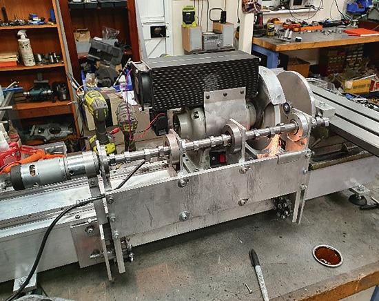
G r i n d i n g t h e Tarcutta T cutt C a m s h a f t
P A R T 1

Gerard Dean makes a pair of camshafts for his V12 motorcycle engine.
There’s an old Aussie tradition – when something goes wrong always blame somebody –somebody else!
Before I name who is to blame for this article about the camshaft grinder shown (photo 1), let’s go way back in time We are standing in the main hall at the 2013 Model Engineer Exhibition when the PA announces ‘The winner of the gold medal for internal combustion engines goes to Gerard Dean from Melbourne, Australia’ Well, I was chesting out – another great Aussie tradition – a tradition that only lasted until the 19 piece crankshaft shattered a few minutes later. The word on the street at the time was that the Oxford Dictionary was going to use my predicament as the uintessential definition of the word embarrassment Tail between my legs, I fronted up to the organisers and asked if

they wanted the medal back No, came the good natured reply, followed by a comment that they really awarded it to me because I travelled from so far away! That made me feel really, really good.
No matter because the word got around that the world’s first etrol engine owered model Tiger tank was on the loose prompting an invite
from the German Bundeswehr to display the Tiger at their armoured base in Munster, Germany (photos 2 and 3) It had to be done because Basil Fawlty told us that orders must be obeyed. This time the new three- iece cran shaft didn’t grenade but I did break a track in the mud Fortunately, a spare was to hand and some German soldiers helped me change the track, prompting us to all agree it reminded us of our time spent together on the Eastern Front back in ‘44
Then followed a display at the North American Model Engineering Society exhibition in Detroit You can imagine my surprise when US customs made me certify that the Tiger’s 88mm gun CANNOT fire a pro e t le or e eas ly mod fied to fire a pro e t le Of all the cities in the world, figured it was a no-brainer to mount a real 12 gauge shotgun on the Tiger for its engagements on the mean streets of Detroit
Okay, back to the articlethe editor is getting nervous Some bright spark asked me
436 Model Engineer 22 March 2024
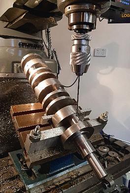
Tarcutta V12 camshaft grinder
Tiger 1 1 opens fre on its home tur undeswehr rmoured ase German
2
1
how I was going to top the Tiger s and went on to suggest I design and make a full-sized engine. Not a bad idea, I thought. It didn’t take long to decide on a 1450cc su ercharged fuel in ected motorcycle engine based on the Tiger engine design The motorcycle would be called the Tarcutta after the Aboriginal name of a small truck stop on the Hume Highway between Melbourne and the small township of Sydney
So, I set too and started machining metal for the block and crankshaft I have included two photographs of these items (photos 4 and 5) but you will have to wait for the descriptions in a following article It dawned on me that I would need two camshafts And that is where this article finally begins sort of
Over 45 years of model engineering I’d made
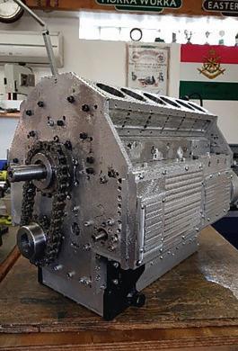
camshafts for the 12cc Wallup ide alve ingle, cc urra Wurra OHC four cylinder, the cc hallenger and the Tiger s ll shafts were made using my hero Len Mason’s built up methods with hardened cam lobes Loctited onto a ground shaft Even I realised that there was Buckley’s chance that this approach would be reliable on a full-size engine
So, what to do? One option would be to get a real camshaft manufacturer to make the shafts. There wasn’t a chance in hell that was going to happen because my old mate Len Mason would shake his head It also goes against my proven philosophy that Rough Enough Is Good Enough As the founder of a manufacturer of super hitec measurement systems for the global can making industry, I have to continually explain my philosophy to our new university-trained

engineers. But I don’t blame the Australian Universities for obsessively trying to make things correctly No, that blame can be sheeted home to one small wet island on the other side the world – Britain Yes, it’s true The country that invented the steam engine and the Triumph Stag (oh deary, deary me) also invented jigs and fi tures They are useless and a total waste of time and I can prove it
An old mate of mine, Gary Sneesby was brought up and learned his engineering trade in Britain He subsequently emigrated to Melbourne and setup a fantastic company, Eccentric Engineering, that has been known to advertise in this august magazine (photo ) His company exports over 70% of production of model engineering tools to Europe, Asia, America and his home island I know Gazza well through the Melbourne Society
of Model & Experimental Engineers and often buy his tools Naturally of course, on receipt of a new tool, I immediately chuck Gazza’s sharpening jig into the junk box This saddened my mate so I thought I’d help him out The result – the soon to be released Eccentric Engineering Flexi-Jig Gary tells me production of the Flexi-Jig will start one day, whatever that means!
Now, where was I? I remember now, I was going to name who is to blame for the following article – yep, you got it – the people at the Model Engineer Magazine! If I didn’t win that gold medal back in ’13, this long sorry train of events would never have happened and I wouldn’t have to write an article on my special camshaft grinder machine Still, the editor says the job has to be done, so tune in next month!
To be continued
437 G R I N D E R www.model-engineer.co.uk
Taracutta V12 crankshaft Eccentric Engineering
The 1 0cc Tiger 1 complete with 19 piece cranksha t
3
Taracutta 1 block during construction
4
6
5
R u s t F o r m a t i o n a n d Pr e v e n t i o n i n t h e Wo r k s h o p
PA RT 1

Neil Raine explains the formation of rust and how it may be prevented
Introduction
In engineering metal is valued for its strength, its versatility and its durability. Since the industrial revolution iron and steel particularly have been relied upon for the construction of buildings, bridges, locomotives, boats, vehicles, machines and infrastructure
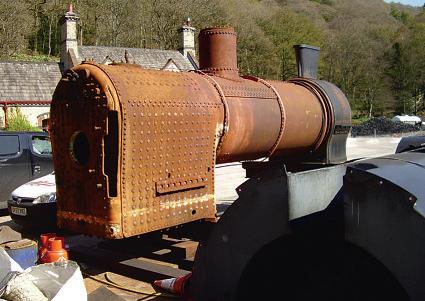
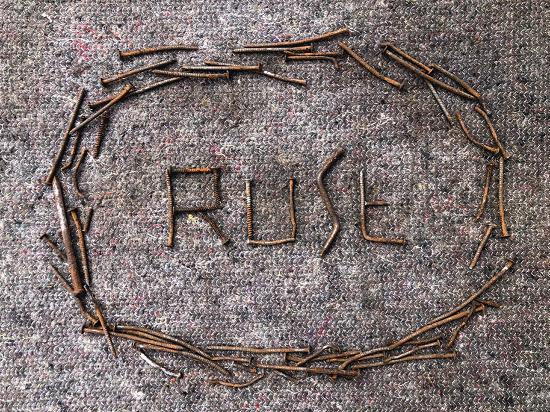
However, unless it is properly protected from the environment, iron and steel will progressively degrade and wea en through the s ecific process of corrosion known as rusting (photos 1-4) Although well understood, the corrosion of iron and steel has proven to be an enduring problem that is difficult to revent and halt Ultimately, the corrosion of iron must be considered the greatest compromise to using it
Model engineers tend to concentrate on the process of creating with metal rather than understanding how it degrades But, when it comes to preserving valued models, machines and tools,

understanding the process that is attempting to progressively disintegrate them is useful Engineering tools and machinery commonly found in home and professional workshops are made predominantly from iron and steel Some components, e g split nuts and bearings, are produced from other materials such as brass and bronze Consequently, most readers will have noticed the beginnings of rust forming on valued tools, projects, machines or components At particular times of the year, it seems there is a persistent
struggle between the effects of cold and dampness and keeping metal in good serviceable order The purpose of this article is to investigate the process of iron and steel corrosion and discuss the practical steps that can be taken to prevent it in the workshop
Features of the workshop building
To begin, in addition to the country of residence and the season of the year, it must be acknowledged that a major contributor to the pace of corrosion of iron and steel
438 Model Engineer 22 March 2024
The fnal resting place o a tug boat on the iver Merse near uncorn ridge Merse side orrosion o the riveted iron hull b saltwater some sections o metal appear to have been cut awa
1
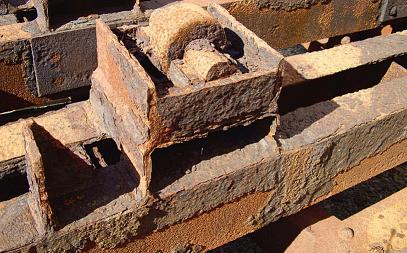
orrosion o the structural parts o a locomotive. The thickened outer la er o rust has aked and allen awa to reveal the progression o corrosion beneath the sur ace xtensive pitting can be seen on the underl ing metal
tools and machinery is the type of building in which the workshop is homed There are many types of building and structural attributes that influence the environmental conditions within it including; a sheltered or exposed aspect, stand-alone building, adjoined building, ground dam roofing, concrete floor, sus ended floor over an airs ace, underfloor ventilation airbric s , ty e of floor surface material (wood, ceramic tiles, concrete), roofing insulation, building insulation (cavity wall), type of heating system wood fire, electric, central heating, gas cylinder), size, number and type of windows, number and type of doors, and draft exclusion. If the rusting of iron and steel is a particular problem in a given workshop over the winter months, then some measures to improve the internal environment are almost certainly needed Some examples of these will be mentioned at the end of the article (in part 2)
Corrosion
Very few metal elements occur naturally in a pure form excepting gold, palladium and platinum (ref 1). All of the other metal elements occur as metalcontaining compounds that are found in mineral deposits called ore To purify metal into a useable form, metal-ore is mined and then processed in varying ways The problem is pure metals are chemically less stable than metal compounds that occur naturally as mineral ore There is a pressure for urified metals to alter in
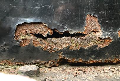
orrosion that has per orated the steel plate o a cab door on a steam locomotive The expansion o rust underneath the paint has caused the paint to blister and ail
order to achieve a more stable chemical structure or state that defines the rocess of corrosion From a practical standpoint, corrosion is the degradation of metal and the loss of its useful properties of strength and malleability. Corrosion is, therefore, a severe threat to the integrity of most human made structures The main incentive for the academic interest into the corrosion of iron and steel stems from the enormous reliance on using the material together with the eye watering economic cost of its deterioration Understanding the corrosion of metals and non-metals, and investigating ways to slow or prevent it, is a scientific disci line ver since 1961, the academic journal Corrosion Science has been dedicated to the subject of both metallic and non-metallic corrosion
Under normal environmental conditions, many metals react with oxygen to form new more chemically stable metal-oxides that are often similar to those found in the naturally occurring mineral ore A group of metals called the base metals (iron, copper, nickel, zinc and lead) are particularly willing to react with oxygen and form more stable compounds; i.e. base metals tend to corrode easily When metals such as brass (alloy), copper, aluminium and silver corrode, there is a familiar dulling of the surface known as tarnish or patina This oxide layer of tarnish is known as a passivation layer (from the adjective ‘passive’) as it seals the metal from the environment
and limits its corrosion further Unfortunately, unlike some other metals, the corrosion of iron is not self-limiting as the oxide layer of rust is permeable to both oxygen and water
As long as the conditions are right, unprotected iron and steel will continue to corrode relentlessly.
Because of the problem of iron and steel rusting, other metals and materials are often favoured for the manufacture of various products, including copper (pipe, electric cables), lead i es, roofing , aluminium (aircraft, bicycles), titanium bicycles, artificial oints , brass (clocks and watches, plumbing valves and joints), plastic (toys, window-frames and doors), carbon fibre s orts cars, bicycles) and composite multilayered materials (aircraft). Yet, when building enormous structures such as ships, bridges and locomotives iron has not yet been surpassed for its abundance, strength, cost and versatility One relatively recent innovation is the use of corten steel or weathering steel This type of steel alloy was developed to form an oxide passivation layer that mild steel does not Corten steel has the typical appearance of rusted iron and nowadays it is often used as an aesthetic architectural attribute on the outside of buildings Corten steel does eventually corrode too but at a slower rate compared to mild-steel
The process of rust-formation
The corrosion of iron is an electrochemical process In
inc galvanised steel lamppost a common sight on man streets The cr stalline structure o the inc plating can clearl be seen
the presence of the catalyst water, refined iron reacts with oxygen to form what is commonly known as the more stable chemical compound iron oxide or rust (Although rust is commonly called iron-oxide, the chemical composition of rust is in fact iron-oxidehydroxide - see below ) There is not one single chemical reaction to describe the formation of rust nor a single chemical compound found within it What might on the surface seem quite simple is much more complicated Investigating corrosion is an entire field of scientific enquiry and a high proportion of this effort is dedicated to iron and steel The following explanation is not complete but is an attempt to outline the important stages whereby pure iron is converted into the compound(s) of rust
The transfer of electrons from iron to oxygen is an important step in the formation of rust Through the chemical process of oxidation, atoms of iron initially give up two electrons from their outer-shell to form the ion Fe2+ (equation 1) In a separate redox-reaction (oxidation-reduction reaction), iron donates a further electron to oxygen atoms to form the ion Fe3+ (equation 2 ) (For clarity only, the oxidised forms of iron Fe2+ and Fe3+, are also often denoted as iron(II) or FeII and iron(III) or FeIII, respectively)
Shown below are two of the many chemical reactions that
439 R U S T www.model-engineer.co.uk >>
2 3 4
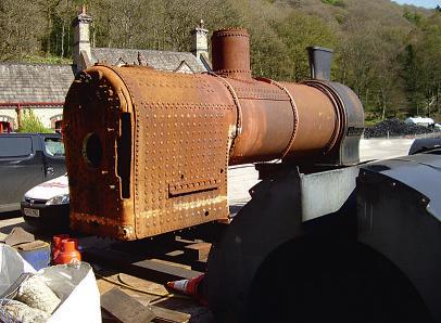
What appears to be mostl sur ace corrosion on a steam locomotive boiler and fre box ust has spread over the entire sur ace area o the iron
are involved in the formation of rust
(Eqn 1) Fe Fe2+ e (Eqn 2) 4Fe2+ 4Fe3+
The chemical ions of iron (Fe2+ and Fe3+) then undergo further chemical reaction with water to produce various compounds of rust, of varying colours (ref 2) that are known as hydrous iron(III) oxides and iron(III) oxide-hydroxideFeO(HO)
There is another way to envisage the above electrochemical reactions taking place In essence, when iron rusts it is said to behave as an electrical-cell. The region where electrons are released from iron represents the anode (positive polarity) (equation 1) In another region of the iron known as the cathode (negative polarity), oxygen atoms accept the free electrons and this is where the compounds of rust are formed (equation 2) Water acts as the electrolyte solution through which the electrons travel The electrical cells responsible for the formation of rust operate at multiple sites on the surface of iron.
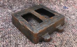
When rust has taken a firm hold of iron photo 5) and the surface is abraded to remove the fla y ironoxide compounds, numerous cavities or pits are often revealed (photo 6) Each pit is believed to be an individual site where iron was oxidised; i e an anodic site The surface pitting is certainly a good visual representation of how iron is chemically removed,

The conse uence o the corrosion o iron. lose up view o the base o an old press ormed iron paint kettle that was ormerl smooth. The sur ace rust was mechanicall removed man ears ago. emaining are the corroded pits where iron was oxidised The scaring is widespread and uite random When magnifed there appears to be iron oxide inside some o the pits
as if dissolved, from one site and deposited elsewhere as rust When magnified, the its appear a reddish-brown colour unlike the other blackened areas of the iron from which the rust was removed. If the pitted surface of rusted iron is attacked with a grinding stone or similar, the clean bright iron beneath is unaffected This confirms that rust formation only occurs on the surface at the interface between the iron, air and moisture
The rate of corrosion of iron is accelerated by the addition of salt (Cl-) to the usual ingredients of water and oxygen (ref 3). One explanation for the accelerated rate of rust formation when exposed to salt is that the addition of chloride ions (Cl-) improves the transport of free electrons and oxidized iron (Fe2+ and Fe3+) from the sites of iron oxidation (anode) to the sites of rust formation (cathode) The aggressive formation of rust in saltwater is a familiar problem for iron hulled boats and ships (photo 2) To slow down the degradation of iron boats, numerous inc sacrificial anodes are often fitted to the outside of the hull. In saltwater, the oxidation of zinc is favoured over the oxidation of iron slowing the formation of rust and sparing the hull somewhat The zinc anodes corrode to virtually nothing and are often replaced if the vessel is overhauled
Images of Titanic, the most famous ship in history, as it rests on the seabed are a spectacular demonstration
of iron rusting in saltwater
Suspended from the hull of the ship are huge yellow-brown stalactite-shaped bodies called rusticles that have the appearance of melted wax. These rusticles contain sulphur and are believed to be mostly the consequence of bacterial activity The corrosion of the iron hull is a stark contrast to the brass portholes and other non-ferrous artifacts that remain essentially unchanged It is remarkable to know that the abundance of iron in a vessel the size of Titanic will eventually degrade completely Bacteria are also known to affect the corrosion of iron and steel by a process called microbiologically influenced corrosion. Bacteria have been shown to both accelerate the formation of rust compounds and remove rust (ref 4) This science has been prompted by the corrosion of underground iron pipelines, used to transport water, sewage, oil and gas, and is a great threat to infrastructure and the economy The connection being that some of the bacteria implicated in the process of iron corrosion underground are known to live in soil
Description of rust formation
The particular environmental conditions and the composition of the metal both influence the susceptibility to rust formation When unprotected iron is exposed to air, the process of corrosion will soon begin Soon after washing a car, the brake discs will often
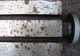
The sur ace o a cast iron slide that was over wintered in the same workshop as the lathe chuck shown in photo 6. e ore renovation the slide was ver rust but was rust ree when stored or winter The slide was oiled once and then covered with oil rags or the winter months between October to pril There remains a covering o oil on the exposed cast iron
change appearance from shiny bright metal to a faint orange colour. Rust formation begins at the interface between the iron and the environment and progresses from the outside inwards The cavities within iron parts such as box-sections and engine cooling waterways rust equally successfully Rust will usually begin as a faint speckling on the surface of the iron and progress to form accumulated patches (photos 7 and 8) that will eventually coalesce to hide the grey iron from sight completely (photos 2 and 5) Surface rust will easily transfer to the hands indicating that it does not strongly adhere to the surface of the iron As time moves on, the surface layer of rust will thicken considerably and then begin to detach as fla es from the mass of iron (photos 2 and 3) At this stage, the appearance of rusting iron is often described as scabby or fla y The fla y rust is very loose and brittle and a blow with a hammer will dislodge it quite easily When the surface of the iron
cast iron steam engine part that shows the beginning o patch iron oxide ormation The colour o the sur ace rust is a t pical reddish brown t this earl stage the rust is unlikel to have caused an pitting
440 Model Engineer 22 March 2024
5 6 7
