2 minute read
1.1 PM ASPV:Simulation Based Assessment of Magnetic Control of a Free Floating Magnet
Next Article

1.1 PM-ASPV: Simulation-Based Assessment of Magnetic Control of a FreeFloating Magnet
A number of discretized controllable magnets are set up circular in a 2D plain. A dipole or spatially extent magnet is assumed in the center. To achieve stability without touching the “walls”, required forces on the dipole must always point towards the center. The required force field is calculated and mapped for all possible dipole positions. The respective local magnetic field around the magnets is calculated analytically and simulated in a transient control loop to affirm stability. Extension to 3D is planned. The project is in early stages, preliminary results look promising.
Contributors: Partner(s): Funding: Duration: A. Zubiaga, V. Lienhard, M. Boldrini, V. Buff, G. Boiger Peter Meyer & Co. AG Innosuisse 2019–2022
There is more than one way to keep a magnetic dipole or spatially extent magnet in a stable position. However, Earnshaw’s Theorem forbids any stable configuration using permanent magnets only, stating that at least one DoF must be fixed or controlled. Research was conducted on various possibilities around this restriction. In magnetic engines this is done by fixating the rotation axis and circular rotating magnetic fields. This requires the rotor to either follow or precede the magnetic field leading to synchronous- or asynchronous-motors. While this might be explored in a later project state, the focusing on a full control-loop is considered more valuable. Based on the Ampère-Dipole model, required fields and forces were assessed by analytical and simple prediction models using excel and BerkleyMadonna in a first step. Figure 1: Exemplary set up of four control magnets and freefloating magnet. The arrows show the direction and magnitude of the magnetization, the streamlines represent the resulting magnetic field. More elaborate analytical and numerical models were implemented in a combination of MATLAB and COMSOL. A recovery central force is implemented that keeps the central magnet floating between the control magnets. The respective force field is calculated and mapped to the 2D area. The magnetic field required is then calculated analytically and numerically and mapped on the discretized control magnets. This mapping is done for each point in space and time for each magnet and should lead to a stable control loop. Torque considerations on the dipole/magnet and gravity effects will be subse-
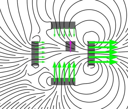
quently included.
Figure 2: The magneto static force (red arrow) acting on the central magnet exerted by the magnetic field (black curves).
The simulation-based PoC in 2D is well on its way, but still needs verification with various effects previously neglected. Leveraging to 3D is planned but is expected to proof more challenging than initially expected. The early stage of the project presents many ways to go and is considered groundwork for various approaches to be assessed in later project stages.
