7 minute read
Chapter 1 • Control Systems


1.1 Open-loop and closed-loop
Control engineering covers all aspects of governing a dynamic system, also called a plant or a process. A plant can be a mechanical system, an electrical system, a thermal system, a fluid system, or a combination of such systems.
A plant can have one or more inputs and one or more outputs. The dynamic behavior of a plant is described by differential equations. Given the model (or the differential equations), inputs, and initial conditions of a plant we can easily calculate its outputs. Generally, a plant is a continuous-time system with its inputs and outputs also continuous in time. For example, an electromagnetic motor is a continuous-time plant whose input (e.g., voltage or current) and its output (e.g., speed or position) are also continuous in time.
Control engineering is based on the theories of system modelling, feedback, system response, and stability. As a result, control engineering is not limited to only one engineering discipline, but is equally applicable to mechanical, chemical, aeronautical, civil, and electrical engineering disciplines.
A plant is normally an open-loop system (Figure 1.1) where an actuating device is used to control the plant directly without using feedback. For example, a motor is expected to rotate when a voltage is applied across its input terminals, but we do not know by how much the motor rotates since there is no knowledge about its output. If the motor shaft is loaded and the motor slows down, there is no knowledge about this. As shown in Figure 1.1, a plant may also have external disturbances affecting its behavior, and in an open-loop system there is no way of knowing or minimizing such disturbances.
Figure 1.1: Open-loop system
In contrast to open-loop control system, in a closed-loop control system (Figure 1.2) the actual plant output is measured and compared with what we would like to see at the plant output. The measure of the output is called feedback signal. The difference between the desired output value and the actual output value is called the error signal. The error signal is used to force the system output to a point such that the desired output value and the actual output value are equal, i.e., the error signal is zero. One of the advantages of closed-loop control, or feedback control is the ability to compensate for disturbances and yield the correct output even in the presence of disturbances. Also, the plant output settles
and remains at the desired value. For example, in a motor speed control system the speed of the motor remains the same when load is applied to the motor shaft. A controller (or compensator) is usually used to read the error signal and drive the plant in such a way that the error tends to zero.
Sensors are devices which measure the plant output. For example, a thermistor is a sensor used to measure the temperature and it can be used in a closed-loop thermal plant control. Similarly, a tachometer or an encoder can be used to measure the rotational speed of a motor and they can be used in closed-loop motor speed control applications. Notice that in electrical systems a power amplifier may be required after the DAC to drive the plant.
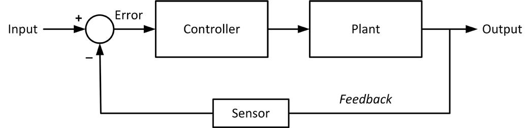
Figure 1.2: Closed-loop system
As you'll discover in a later Chapter, most sensors are analog devices giving analog voltage or current outputs. These sensors can be used directly in analog systems where the inputs, controller, plant, and the outputs are all analog variables.
1.2 Microcontroller in the loop
Nowadays, practically all control systems are microcontroller based, where a microcontroller is used as the central control device. Some sensors (e.g., temperature, pressure, humidity etc.) provide digital outputs and can be connected directly to a microcontroller. Analog sensors cannot be connected directly to a microcontroller. An analog-to-digital converter (ADC) is needed to convert the analog signal into digital form so that it can be fed to a microcontroller.
Figure 1.3 shows a digital control system where the input and the output of the sensor are assumed to be analog. An ADC is used to periodically convert the error signal into digital form and this is fed to a digital controller which is usually a microcontroller. The microcontroller implements a control algorithm (e.g., PID algorithm) and its output is converted into analog form using a digital-to-analog converter (DAC) so that it can drive the plant to set the plant output to the desired value.
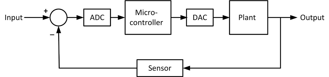
Figure 1.3: Digital control system.
Figure 1.4 shows the block diagram of a digital control system where the ADC is shown as a sampler. Most microcontrollers incorporate ADC and DAC modules and these are shown as part of the microcontroller in Figure 1.4.
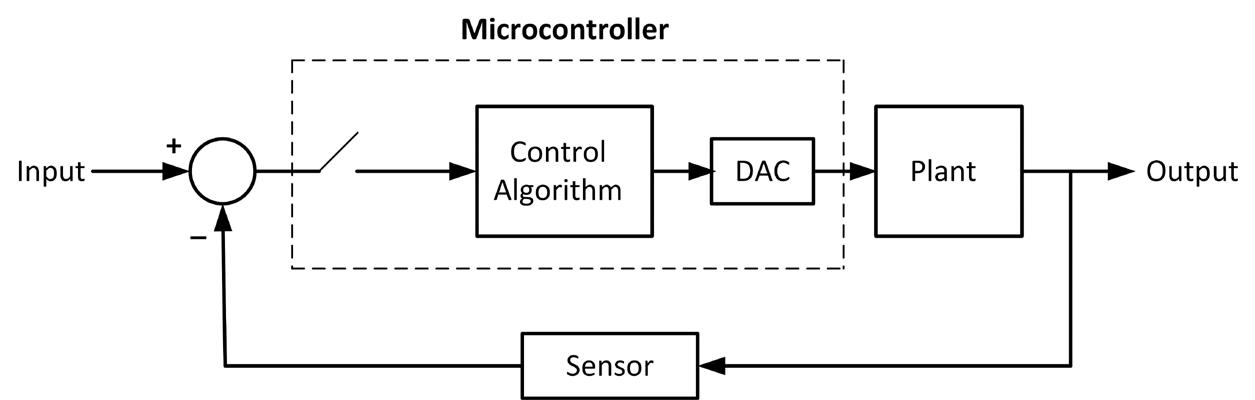
Figure 1.4: Block diagram of a digital control system.
In Figure 1.4 the input and the sensor output are analog signals. A variation of this system is shown in Figure 1.5 where the input is digital and is either hardcoded to the microcontroller software or is input using a suitable input device such as a keypad. Here, a sensor with digital output is used and is connected directly to the microcontroller.
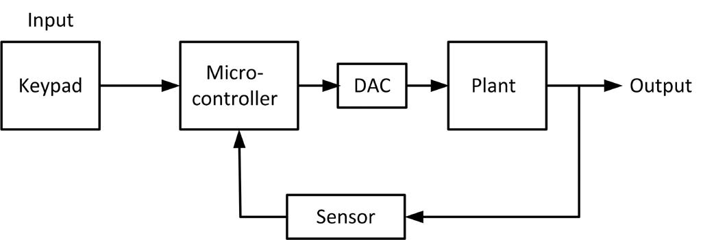
Figure 1.5: Another variation of digital control.
Figure 1.6 shows a typical analog speed control system. Here, the desired speed is set using a potentiometer. The speed of the motor is measured using a tachometer and is fed back to a difference amplifier. The output of this amplifier is the error signal which is input to an analog controller consisting of operational amplifiers. The output of the controller drives the motor through a power amplifier to achieve the desired speed.

Figure 1.6: Analog speed control system.
Figure 1.7 shows the digital equivalent of Figure 1.6. Here, a digital encoder is used to measure the motor speed and this is fed to the microcontroller together with the desired speed where the speed is set using a keypad. The microcontroller implements the control algorithm and sends its output to the power amplifier in the form of a Pulse Width-Modulated (PWM) signal which in turn provides power to the motor to set the speed at the desired value.
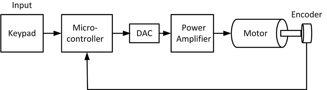
Figure 1.7: Digital speed control system.
Since a plant can be controlled using an analog approach, you might be tempted to ask why use digital control? In the 1960s, computers and microcontrollers were bulky and very expensive devices and their use as digital controllers was not justified. They were only used in large and expensive plants, such as large chemical processing sites or oil refineries. Since the introduction of microcontrollers in 1970s, the cost and size of digital controllers have dropped dramatically. As a result of this, also from the drop in the price of other digital components such as memories, interest in using digital control has soared in the past few decades.
Digital controllers have several advantages compared to analog controllers:
• Improved user interface. Digital controllers can display the system parameters and response graphically on a monitor. • Digital controllers can be configured to be adaptive. Complex controller algorithms can easily be implemented using digital controllers. • The cost of digital controllers are lower than the analog ones, especially if additional control loops have to be added to the system. • It is easy to tune digital controllers. All that is required is to change pertinent parameters in software. • Digital controllers are more dependable than the analog ones and they are not affected by environmental factors such as component aging, component tolerances, etc. • Digital controllers can be modified easily through software. Modification of an analog controller on the other hand usually require re-wiring or the use of different or additional components. • Almost all analog controllers have been replaced over time by digital ones.
1.3 Control system design
Control system design is an engineering process and it must be carried out systematically. The major steps to design a physical control system can be summarized by the following steps:
• Define the system input and output • Define the variable to be controlled • Derive a mathematical model (differential equations) of the system • Decide whether analog or digital control is to be used • Choose a suitable sensor • Choose a microcontroller (if digital control is to be used) • Choose other components such as power supply, op-amp, power amplifier etc. • Draw a block diagram of the system • Describe the controller to be used and develop the control algorithm • Adjust the parameters of the chosen controller • Simulate the overall system (if simulation tools such as MATLAB are available) • Assemble the system and observe its behavior. If the system response is as desired, that concludes the project. If on the other hand the system does not behave as required, go back to choose a different controller or to re-adjust the controller parameters, re-simulate and re-test.
