RIGCHECK CARD
For Product & Inspection Services information call:
For locations and more Information regarding Bullivants products & services call or visit on:
Asset Management Register:
www.bullivants.com/services/beam

www.bullivants.com
This RIGCHECK card has been produced as a ‘guide only’ based on manufacturers specifications and Australian Standards. Bullivants accepts no responsibility should any product fail in service based on information within this card.
All information provided is correct at the time of printing and is subject to change without notice.
I NSPECTION • RIGGING • LIFTING • RESTRAINT • RECOVERY • TESTIN G •
Code: 44203002
Item
BV-QMS-TD-03A
STEPS TO PERFORMING A SAFE LIFT
1. Know the WEIGHT of the load, if not, ask your supervisor
2. Know the APPLICATION requirements (single or multi leg, basket or choke hitch)
3. Ensure the CORRECT gear is selected for the lift
4. INSPECT all gear before use
5. FLOAT the load and check for BALANCE
6. LIFT the load slowly and controlled
7. Establish a LANDING PAD with packers to prevent crush of the lifting gear
8. Always RE-INSPECT the gear
9. STORE gear off the ground in a clean dry area
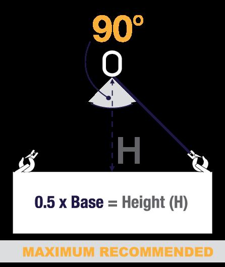
Maximum limit under Australian Standards
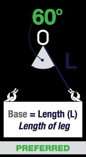
LIFTING LIMITATIONS – HOW TO CALCULATE A SAFE ANGLE FOR LIFTING
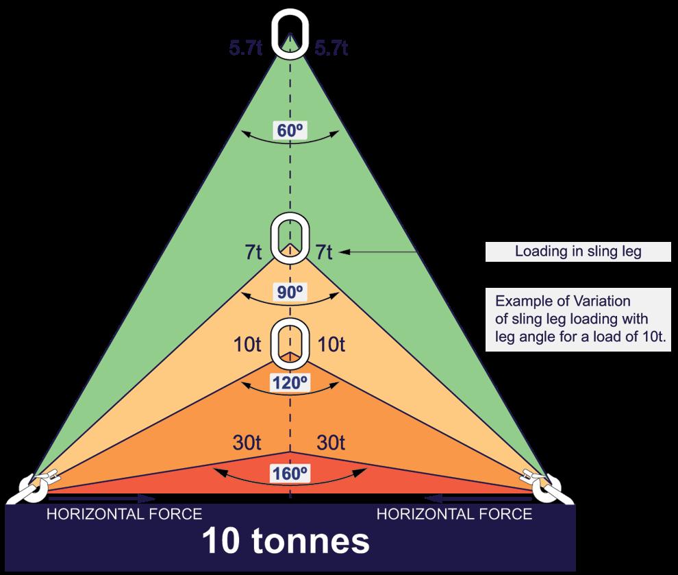
WHY DO ANGLES AFFECT LOADS?
All multi-leg slings exert a horizontal component of force, which increases as the included angle becomes greater.
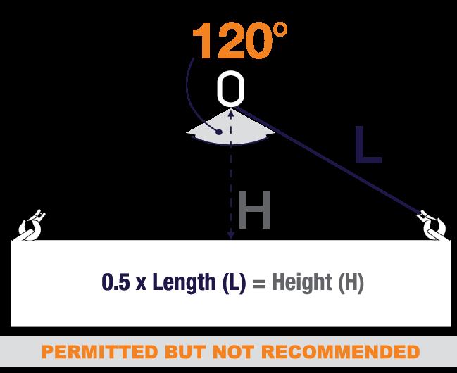
No sling should be used if the included angle exceeds 120º, as beyond this point the forces in the legs drastically increase, as indicated in the diagram.
NOTE: Do not use multi-leg slings at angles of greater than 120º
WORKING LOAD LIMITS (TONNES)
Notes:
1. Some shortening devices, such as grab hooks may derate the WLL. Advice regarding the appropriate deration should be sought from the manufacturer.
2. The determination of the angle of the multi-leg sling is the largest included angle at the apex of the configuration.
3. Reeved slings and basket slings, in a two leg configuration have a maximum angle for use of 60°.
conditions, please contact our technical team for advice.
STEEL
SLINGS – SINGLE & MULTI-LEG ASSEMBLIES - EN10204 3.1
STAINLESS
CHAIN
Temperature °C = deration -40° to + 350° = none 350° to 700° = only permitted
60* CHAIN SIZE MM STRAIGHT SLING OR ADJUSTABLE SLING WITH NO DERATION REEVED SLING BASKET SLING MAX 60° STRAIGHT SLING (NOTE 2) REEVED SLING (NOTES 2 & 3) ENDLESS CHAIN SLING 60° 90° 120° Max Angle 60° Max Angle 60°
60*
in certain
GRADE
GRADE
Load Factor > 1.0 0.75 1.3 1.73 1.41 1.0 1.3 1.5 WOX 4-6 0.4 0.32 0.52 0.69 0.56 0.4 0.52 0.6 WOX 5-6 0.63 0.5 0.81 1.09 0.85 0.63 0.81 0.94 WOX 6-6 0.9 0.72 1.17 1.55 1.25 0.9 1.17 1.35 WOX 7-6 1.25 1.0 1.62 2.16 1.75 1.25 1.62 1.87 WOX 8-6 1.6 1.28 2.08 2.76 2.2 1.6 2.08 2.4 WOX 10-6 2.5 2.0 3.25 4.32 3.5 2.5 3.25 3.75 WOX 13-6 4.25 3.4 5.52 7.35 5.95 4.25 5.52 6.37 WOX 16-6 6.3 5.04 8.19 10.9 8.8 6.3 8.19 9.45 WOX 20-5 8.0 6.4 10.4 13.84 11.2 8.0 10.4 12.0 WOX 26-4 + 12.0 9.6 - - - - - 18.0
*PEWAG Grade 60 slings are designed, manufactured, and tested in accordance with EN10204 3.1
ALLOY CHAIN SLINGS – SINGLE & MULTI-LEG ASSEMBLIES – AS3775
Notes:
1. Some shortening devices, such as grab hooks may derate the WLL. Advice regarding the appropriate deration should be sought from the manufacturer.
2. The determination of the angle of the multi-leg sling is the largest included angle at the apex of the configuration.
3. Reeved slings and basket slings, in a two leg configuration have a maximum angle for use of 60°.
CHAIN SIZE MM STRAIGHT SLING OR ADJUSTABLE SLING WITH NO DERATION ADJUSTABLE SLING WITH DERATION (NOTE 1) REEVED SLING BASKET SLING MAX 60° STRAIGHT SLING (NOTE 2) REEVED SLING (NOTES 2 & 3) BASKET SLING (NOTES 2 & 3) 60° 90° 120° Max Angle 60° Max Angle 60°
GRADE T(80)
GRADE T(80)
6 1.1 0.8 0.8 1.5 1.9 1.6 1.1 1.5 2.5 7 1.5 1.1 1.1 2.0 2.6 2.1 1.5 2.0 3.4 8 2.0 1.5 1.5 2.6 3.5 2.8 2.0 2.6 4.5 10 3.2 2.4 2.4 4.1 5.5 4.5 3.2 4.1 7.2 13 5.3 4.0 4.0 6.9 9.2 7.5 5.3 6.9 11.9 16 8.0 6.0 6.0 10.4 13.8 11.3 8.0 10.4 18.0 19 11.2 8.4 8.4 14.6 19.4 15.8 11.2 14.6 25.2 20 12.5 9.4 9.4 16.3 21.6 17.6 12.5 16.3 28.1 22 15.0 11.3 11.3 19.5 26.0 21.2 15.0 19.5 33.8 26 21.2 15.9 15.9 27.6 36.7 29.9 21.2 27.6 47.7 32 31.5 23.6 23.6 41.0 54.5 44.4 31.5 41.0 70.9
WORKING LOAD LIMITS (TONNES)
Temperature °C = deration -40° to + 200° = none + 200° to 300° = 10% + 300° to + 400° = 25%
ALLOY CHAIN SLINGS – SINGLE & MULTI-LEG ASSEMBLIES – AS3775
Notes:
1. Some shortening devices, such as grab hooks may derate the WLL. Advice regarding the appropriate deration should be sought from the manufacturer.
2. The determination of the angle of the multi-leg sling is the largest included angle at the apex of the configuration.
3. Reeved slings and basket slings, in a two leg configuration have a maximum angle for use of 60°.
Bullivants Grade 100 alloy chain cannot be used in applications or environments exceeding a temperature of 200°C.
CHAIN SIZE MM STRAIGHT SLING OR ADJUSTABLE SLING WITH NO DERATION ADJUSTABLE SLING WITH DERATION (NOTE 1) REEVED SLING BASKET SLING MAX 60° STRAIGHT SLING (NOTE 2) REEVED SLING (NOTES 2 & 3) BASKET SLING (NOTES 2 & 3) 60° 90° 120° Max Angle 60° Max Angle 60°
GRADE V(100)
GRADE V(100)
5 1.0 0.8 0.8 1.3 1.7 1.4 1.0 1.3 2.3 6 1.4 1.1 1.1 1.8 2.4 2.0 1.4 1.8 3.2 7 1.9 1.4 1.4 2.5 3.3 2.7 1.9 2.5 4.3 8 2.5 1.9 1.9 3.3 4.3 3.5 2.5 3.3 5.6 10 4.0 3.0 3.0 5.2 6.9 5.6 4.0 5.2 9.0 13 6.7 5.0 5.0 8.7 11.6 9.4 6.7 8.7 15.1 16 10.0 7.5 7.5 13.0 17.3 14.1 10.0 13.0 22.5 18 12.5 9.4 9.4 16.3 21.6 17.6 12.5 16.3 28.1 19 14.0 10.5 10.5 18.2 24.2 19.7 14.0 18.2 31.5 20 16.0 12.0 12.0 20.8 27.7 22.6 16.0 20.8 36.0 22 19.0 14.3 14.3 24.7 32.9 26.8 19.0 24.7 42.8 23 21.0 15.8 15.8 27.3 36.3 29.6 21.0 27.3 47.3 26 26.5 19.9 19.9 34.5 45.8 37.4 26.5 34.5 59.6 28 31.5 23.6 23.6 41.0 54.5 44.4 31.5 41.0 70.9 32 40.0 30.0 30.0 52.0 69.2 56.4 40.0 52.0 90.0
WORKING LOAD LIMITS (TONNES)
GRADE 120* CHAIN SLINGS – SINGLE & MULTI-LEG ASSEMBLIES - AS3775
WORKING LOAD LIMITS (TONNES)
Notes:
1. Some shortening devices, such as grab hooks may derate the WLL. Advice regarding the appropriate deration should be sought from the manufacturer.
2. The determination of the angle of the multi-leg sling is the largest included angle at the apex of the configuration.
3. Reeved slings and basket slings, in a two leg configuration have a maximum angle for use of 60°.
*RUD ICE120 Slings are designed, manufactured and tested in accordance with general requirements of DIN EN 818, DIN EN 1677, AS3775.1, AS2321 & AS3776.
Temperature °C = deration -40° to +200° = none +200° to +300° = 90% +300° to +380° = 60%
120 CHAIN SIZE MM STRAIGHT SLING OR ADJUSTABLE SLING WITH NO DERATION REEVED SLING BASKET SLING MAX 60° STRAIGHT SLING (NOTE 2) REEVED SLING (NOTES 2 & 3) BASKET SLIING (NOTES 2 &3) 60° 90° 120° Max Angle 60° Max Angle 60°
GRADE
GRADE 120
Load Factor > 1.0 0.75 1.3 1.73 1.41 1.0 1.3 2.25 4 0.8 0.6 1.0 1.4 1.1 0.8 1.0 1.8 6 1.8 1.4 2.3 3.1 2.5 1.8 2.3 4.1 8 3.0 2.3 3.9 5.2 4.2 3.0 3.9 6.8 10 5.0 3.8 6.5 8.7 7.1 5.0 6.5 11.3 13 8.0 6.0 10.4 13.8 11.3 8.0 10.4 18.0 16 12.5 9.4 16.3 21.6 17.6 12.5 16.3 28.1
HMPE AmSteel®-Blue SLINGS IN ACCORDANCE WITH AS18264/FRS0412
Supplied with Thimble ends or soft loops (with or without protective sleeves)
NOTE: Interfacing components shall not be less than 1.5 times the rope diameter otherwise a 25% deration applies to the WLL as stated within this chart. Bending Ratios for grommets shall not be less than 4 times the rope diameter.
*Double Grommets used with a Ramshorn Hook only.
AmSteel®-Blue
OF LOADING SLING DIRECT LOADED CHOKE HITCH BASKET HITCH DIRECT LOADED GROMMETS Single Single Round Loaded Single Square Loaded Single Round Loaded Multileg Single *Double Included Angle 0° 60° 90° 120° 0° to 60° 90° 120° Nom. Dia. (mm) MBF (kN) AmSteel®-Blue
METHOD
12 136.0 2.77 2.08 1.39 5.55 4.80 3.91 2.77 4.80 3.91 2.77 4.43 7.76 16 211.8 4.32 3.24 2.16 8.64 7.47 6.09 4.32 7.47 6.09 4.32 6.91 11.95 18 258.0 5.26 3.94 2.63 10.52 9.10 7.42 5.26 9.10 7.42 5.26 8.41 14.54 22 364.0 7.42 5.57 3.71 14.84 12.84 10.46 7.42 12.84 10.46 7.42 11.87 20.53 24 436.5 8.90 6.67 4.45 17.80 15.40 12.55 8.90 15.40 12.55 8.90 14.24 24.63 28 592.5 12.08 9.06 6.04 24.16 20.90 17.03 12.08 20.90 17.03 12.08 19.32 33.42 30 661.1 13.48 10.11 6.74 26.96 23.32 19.01 13.48 23.32 19.01 13.48 21.56 37.30 32 736.7 15.02 11.27 7.51 30.04 25.98 21.18 15.02 25.98 21.18 15.02 24.00 41.52 36 913.3 18.62 13.97 9.31 37.24 32.21 26.25 18.62 32.21 26.25 18.62 29.80 51.55 42 1343.9 27.40 20.55 13.70 54.80 47.40 38.63 27.40 47.40 38.63 27.40 43.84 75.85 56 2148.0 43.79 32.84 21.90 87.58 75.76 61.75 43.79 75.76 61.75 43.79 70.00 121.10 64 2648.7 54.00 40.50 27.00 108.00 93.42 76.14 54.00 93.42 76.14 54.00 86.40 149.47 80 4031.9 82.20 61.65 41.10 164.40 142.21 115.90 82.20 142.21 115.90 82.20 131.52 227.52 88 5846.7 119.20 89.40 59.60 238.40 206.21 168.07 119.20 206.21 168.07 119.20 190.72 329.94
WORKING LOAD LIMITS (TONNES)
WIRE ROPE SLINGS – SINGLE, TWO, THREE & FOUR LEG WITH FERRULE
Secured eyes, using galvanised or black wire rope in accordance with AS1666.1
METHOD OF LOADING SLING DIRECT LOADED CHOKE HITCH BASKET HITCH DIRECT LOADED CHOKE HITCH ROUND LOAD Round Loaded Rectangle Loaded Round Load Single Wrap Double Wrap Included Angle - - - 0° 60° 90° 120° 0° to 60° 90° 120° 0° to 45° 0° to 60° Nom. Dia. (mm) MBF (kN)
1570 GRADE FIBRE CORE
1570 GRADE FIBRE CORE
8 28.2 0.55 0.41 0.27 1.11 0.96 0.78 0.55 0.96 0.78 0.55 0.72 9 35.6 0.70 0.52 0.35 1.40 1.21 0.99 0.70 1.21 0.99 0.70 0.91 10 44.0 0.86 0.65 0.43 1.73 1.50 1.22 0.86 1.50 1.22 0.86 1.13 11 53.2 1.05 0.78 0.52 2.10 1.81 1.48 1.05 1.81 1.48 1.05 1.36 12 63.3 1.23 0.92 0.61 2.47 2.14 1.74 1.23 2.14 1.74 1.23 1.61 13 74.3 1.47 1.10 0.73 2.94 2.54 2.07 1.47 2.54 2.07 1.47 1.91 14 86.2 1.70 1.27 0.85 3.40 2.94 2.40 1.70 2.94 2.40 1.70 2.21 16 113 2.22 1.67 1.11 4.45 3.85 3.14 2.22 3.85 3.14 2.22 2.89 18 143 2.80 2.10 1.40 5.61 4.85 3.95 2.80 4.85 3.95 2.80 3.65 20 176 3.48 2.61 1.74 6.97 6.03 4.91 3.48 6.03 4.91 3.48 4.53 22 213 4.20 3.15 2.10 8.40 7.27 5.92 4.20 7.27 5.92 4.20 5.46 24 253 5.01 3.76 2.50 10.03 8.67 7.07 5.01 8.67 7.07 5.01 6.52 26 297 5.88 4.41 2.94 11.77 10.18 8.30 5.88 10.18 8.30 5.88 7.65 28 345 6.81 5.11 3.40 13.63 11.79 9.61 6.81 11.79 9.61 6.81 8.86 32 450 8.90 6.68 4.45 17.81 15.41 12.56 8.90 15.41 12.56 8.90 11.58
WORKING LOAD LIMITS (TONNES)
ROPE CORE
OF LOADING SLING DIRECT LOADED CHOKE HITCH BASKET HITCH DIRECT LOADED CHOKE HITCH ROUND LOAD Round Loaded Rectangle Loaded Round Load Single Wrap Double Wrap Included Angle - - - 0° 60° 90° 120° 0° to 60° 90° 120° 0° to 45° 0° to 60° Nom. Dia. (mm) MBF (kN)
1770 GRADE WIRE
METHOD
CORE
1770 GRADE WIRE ROPE
8 40.2 0.78 0.58 0.39 1.56 1.35 1.10 0.78 1.35 1.10 0.78 1.01 9 51.1 0.99 0.74 0.49 1.98 1.71 1.40 0.99 1.71 1.40 0.99 1.29 10 63.1 1.22 0.92 0.61 2.40 2.10 1.72 1.22 2.10 1.72 1.22 1.59 11 76.3 1.48 1.11 0.74 3.00 2.60 2.10 1.48 2.60 2.10 1.48 1.92 12 90.8 1.76 1.32 0.88 3.50 3.00 2.50 1.76 3.00 2.50 1.76 2.30 13 107 2.10 1.55 1.04 4.10 3.60 2.90 2.10 3.60 2.90 2.10 2.70 14 124 2.40 1.80 1.20 4.80 4.20 3.40 2.40 4.20 3.40 2.40 3.10 16 161 3.10 2.30 1.56 6.20 5.40 4.40 3.10 5.40 4.40 3.10 4.10 18 204 4.00 3.00 1.98 7.90 6.80 5.60 4.00 6.80 5.60 4.00 5.10 20 252 4.90 3.70 2.40 9.80 8.40 6.90 4.90 8.40 6.90 4.90 6.30 22 305 5.90 4.40 3.00 11.80 10.20 8.30 5.90 10.20 8.30 5.90 7.70 24 363 7.00 5.30 3.50 14.10 12.20 9.90 7.00 12.20 9.90 7.00 9.10 26 426 8.30 6.20 4.10 16.50 14.30 11.60 8.30 14.30 11.60 8.30 10.70 28 494 9.60 7.20 4.80 19.10 16.60 13.50 9.60 16.60 13.50 9.60 12.40 32 646 12.50 9.40 6.30 25.00 22.00 17.60 12.50 22.00 17.60 12.50 16.30 36 817 15.80 11.90 7.90 32.00 27.00 22.00 15.80 27.00 22.00 15.80 21.00 40 1010 19.60 14.70 9.80 39.00 34.00 28.00 19.60 34.00 28.00 19.60 25.00 44 1220 24.00 17.70 11.80 47.00 41.00 33.00 24.00 41.00 33.00 24.00 31.00 48 1450 28.00 21.00 14.00 56.00 49.00 40.00 28.00 49.00 40.00 28.00 37.00 52 1710 33.00 25.00 16.60 66.00 57.00 47.00 33.00 57.00 47.00 33.00 43.00 56 1980 38.00 29.00 19.20 77.00 66.00 54.00 38.00 66.00 54.00 38.00 50.00 60 2270 44.00 33.00 22.00 88.00 76.00 62.00 44.00 76.00 62.00 44.00 57.00
WORKING LOAD LIMITS (TONNES)
SYNTHETIC SLINGS – FLAT WEBBING SLING – AS1353, ROUNDSLINGS – AS4497
WLL’s above 10 tonne - contact Bullivants for support or refer to AS4497 or AS1353.
The colour of the working load limit tag shall identify the type of fibre used for round and flat type synthetic slings as follows:
Nylon - Green
Polyester - Blue
Polypropylene - Brown
Aramid Polymide - Yellow
MATERIAL COLOUR MARKED WLL STRAIGHT LIFT CHOKED STRAIGHT LIFT PARALLEL BASKET BASKET HITCH OR 2, 3 AND 4 LEG SLINGS CHOKE HITCH OR 2, 3 AND 4 LEG SLINGS α = 60° = 90° α = 120° Single Wrap α = max 45° Double Wrap α = max 60° or α° α° α° α°
LIMITS (TONNES) Violet 1 1 0.8 2 1.7 1.4 1 1.38 Green 2 2 1.6 4 3.4 2.8 2 2.76 Yellow 3 3 2.4 6 5.1 4.2 3 4.14 Grey 4 4 3.2 8 6.9 5.6 4 5.52 Red 5 5 4.0 10 8.6 7.0 5 6.9 Brown 6 6 4.8 12 10.3 8.4 6 8.28 Blue 8 8 6.4 16 13.8 11.2 8 11.04 Orange 10 10 8.0 20 17.3 14.1 10 13.8
WORKING LOAD
SHACKLES – AS2741
Grade S Alloy Bow & Dee Type Shackles (Screw pin & safety pin available)
Sizes up to 1500t available upon request
WLL (TONNES) SIZE d (MM) D (MM) W (MM) B (MM) BOW TYPE L (MM) DEE TYPE L (MM) 0.33 5 6 10 15 22 N/A 0.50 6 8 12 20 29 22 0.75 8 10 13 21 31 26 1.0 10 11 18 26 37 32 1.5 11 13 18 29 43 37 2.0 13 16 21 33 48 41 3.2 16 19 27 43 61 51 4.7 19 22 32 51 72 60 6.5 22 25 37 58 84 71 8.5 25 29 43 68 95 81 9.5 29 32 46 74 108 90 12.0 32 35 52 83 119 100 13.5 35 38 57 92 133 113 17.0 38 41 60 98 146 124 25.0 44 51 73 127 178 146 35.0 51 57 83 146 197 171 45.0 57 63 95 160 222 181 55.0 63 70 105 184 267 203 85.0 76 83 127 200 330 229 120.0 89 95 146 241 381 267 150.00 102 108 165 279 432 318
COLLARED EYEBOLTS & EYENUTS – GRADE 4 – AS2317
NOMINAL THREAD SIZE SINGLE EYEBOLT OR EYENUT PAIR OF EYEBOLTS OR EYENUTS Transverse t (F2) Axial t (F1) Transverse t Maximum Included Angle 30° t Maximum Included Angle 60° t Maximum Included Angle 90° t -5º
M10 0.06 0.25 0.12 0.31 0.20 0.12 M12 0.10 0.40 0.20 0.50 0.32 0.20 M16 0.20 0.80 0.40 1.00 0.64 0.40 M20 0.40 1.6 0.80 2.0 1.28 0.80 M22 0.50 2.0 1.00 2.5 1.60 1.00 M24 0.62 2.5 1.25 3.1 2.0 1.25 M30 1.00 4.0 2.0 5.0 3.2 2.0 M33 1.25 5.0 2.5 6.3 4.0 2.5 M36 1.57 6.3 3.1 7.9 5.0 3.1 M39 1.75 7.0 3.5 8.8 5.6 3.5 M42 2.0 8.0 4.0 10.0 6.4 4.0 M48 2.5 10.0 5.0 12.6 8.0 5.0 M56 3.7 15.0 7.5 18.9 12.0 7.5 M64 5.0 20.0 10.0 25.0 16.0 10.0 M72 6.2 25.0 12.5 31.0 20.0 12.5 M76 7.5 30.0 15.0 37.0 24.0 15.0
WORKING LOAD LIMITS (TONNES)
