Keeping up in a changing landscape: your predictions for 2019
Causes and variables of waterhammer

Procuring engines for a new power station
ISSUE 26 SUMMER 2019
pumpindustry

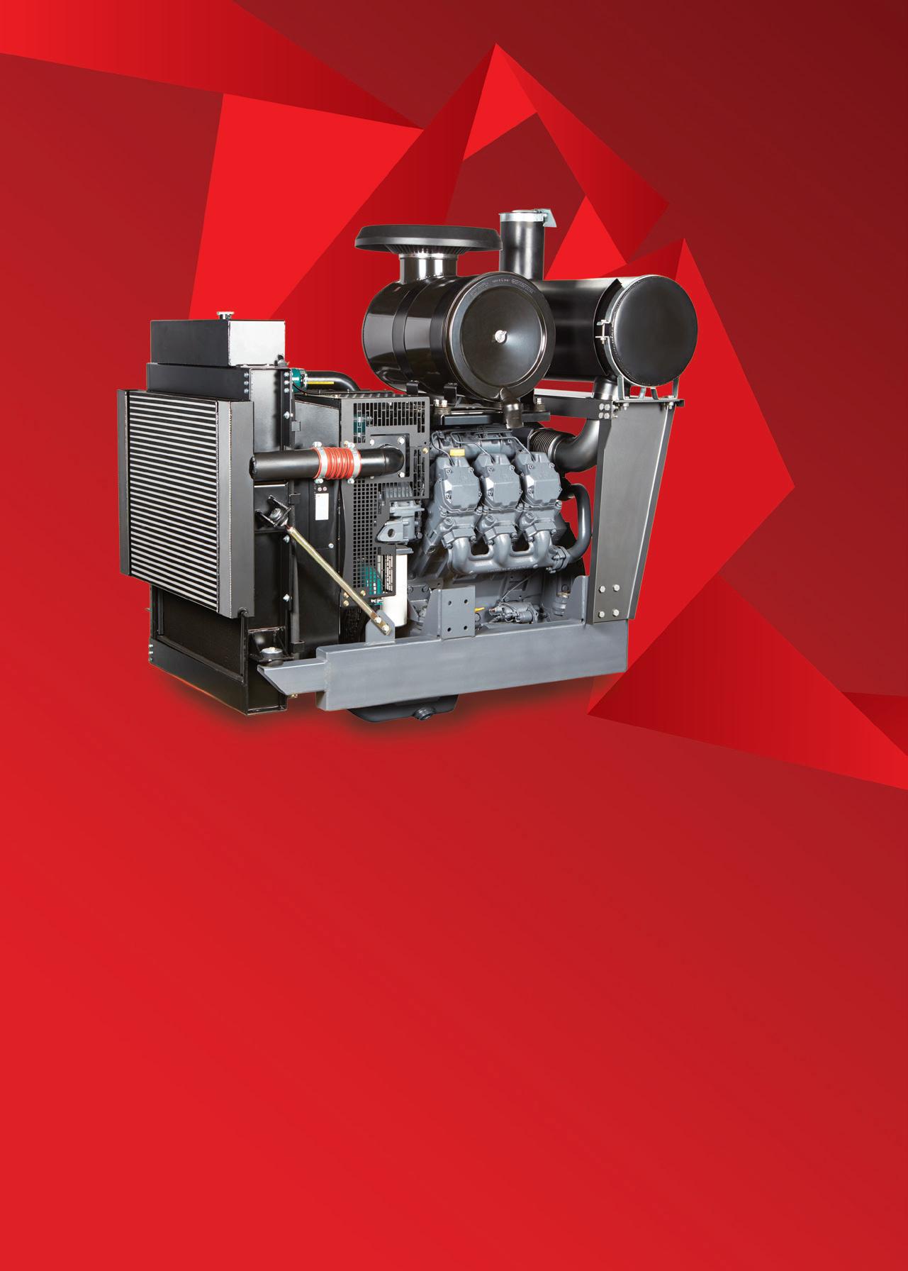
Our No.1 engine solution is now bigger than ever.
DEUTZ Drive is a fully assembled ‘plug and play’ Power Pack package, that’s beautifully designed and can be customised to suit any stationary platform.
The bigger range boasts more horsepower, is easy to assemble and uses less fuel.
Best of all, you can control it from anywhere with remote start and stop.
Proudly Australian, DEUTZ Drive is the preferred pump and irrigation solution.

It just got bigger. DEUTZ Australia | www.deutz.com.au | deutzoz@deutz.com | 03 9549 8400 The engine company. 21-300 kW available


Pump Industry Australia Incorporated
PO Box 55, Stuarts Point NSW 2441 Australia
Ph/Fax: (02) 6569 0160 pumpsaustralia@bigpond.com
PIA Executive Council 2019
John Inkster - President Brown Brothers Engineers
James Blannin - Vice President Stevco Pumps & Seals
Kevin Wilson - Treasurer/Secretary Executive Officer
Alan Rowan - Councillor
Executive Officer - Publications and Training, Life Member
Ken Kugler
Executive Officer - Standards, Life Member
David Alexander - Councillor KSB Australia
Andrew Black - Councillor Envirotech Water Solutions
Mike Bauer - Councillor DynaPumps
Jim Athanas - Councillor Xylem Water Solutions
Hem Prakash - Councillor Davey Water Products
Anant Yuvarajah - Councillor ASC Water Tanks
President’s welcome
Welcome all to this frst edition for the year and my frst as President of PIA. Let me frst thank Dave Alexander for his sterling job as President over the last two years. Whilst Dave has stepped down as President, he is remaining as a Councillor. His experience as former President will be an invaluable voice and continuing source of knowledge to both the incoming Council and as a representative of the industry.
In November, Pump Industry Australia held the AGM at the Box Hill Golf Club in Melbourne, where a new Council for 2019 was elected by members. We are saying farewell to some retiring Councillors and welcoming some new faces. First of all, let me thank those who are moving on for their contribution to the PIA: retiring from their roles on the Council are Keith Sanders, Ashley White and Malcolm Eyre.
Special mention should be made of Keith Sanders who has been a stalwart of the PIA for — should I say — some decades from its inception as the APMA, and has been a tireless and dedicated contributor throughout that period. Keith has served as Secretary, President, Councillor and more recently as the Marketing and Statistics Executive Ofcer, and whilst I am sure his services won’t entirely be lost to us, the PIA and Council will certainly miss his depth and breadth of knowledge of the workings of the pump industry.
Thank you Keith for your considerable and valued contribution to the PIA over such a long period of time. We also thank Ashley and Malcolm, and on behalf of all members, we thank you both for your contribution to the PIA.
Joining the Council, we have Hem Prakash from Davey Water Products and Anant Yuvarajah of ASC Watertanks — we congratulate you both on becoming Councillors and extend a warm welcome to you.
Continuing on as a Councillor is James Blannin from Stevco, who has also accepted the position of Vice President, and along with Hem and Anant, will introduce somewhat of a ‘youthful enthusiasm’ to Council, which is encouraging! Also continuing in their commitment to their roles as Councillors are Alan Rowan, Andrew Black, Mike Bauer and Jim Athanas. With James stepping into the role of VP, this presents a vacancy for one more representative on the Council, so if you would like to take up this position or know of someone who might, please don’t be shy and make contact.
It is clear from the AGM that the PIA faces challenges; it has been said that what is needed is a set of shortterm objectives specifcally related to the current state of the association and the industry, and how successful we have been in representing the expectations of members in the past. The incoming Council faces challenges, but I am confdent that where there’s a will there's a way; the incoming Council will review the feedback from members at large and work to ensure that our members — current and future — obtain value from the services PIA provides and, more importantly, they are what you see as being relevant to you and your business.
See you all in 2019.
John Inkster
2 pump industry | Summer 2019 | Issue 26 www.pumpindustry.com.au PUMP INDUSTRY
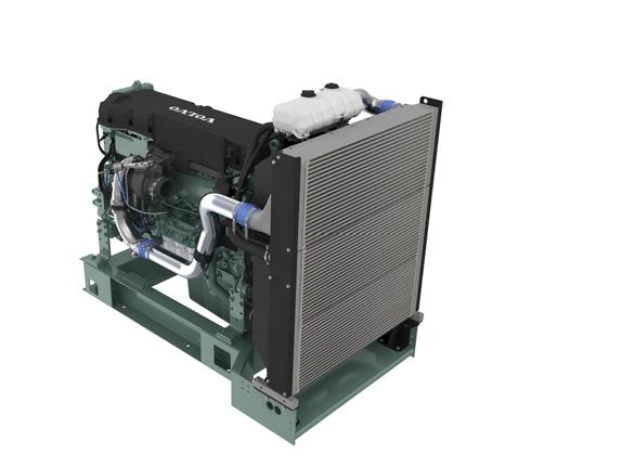
Volvo Penta. Robust, fuel efcient industrial diesel engines that keep running even in the toughest conditions. Easy to install, operate and maintain. A powerful partnership you can trust all the way from the drawing board throughout the operational life of your engine. Competitively priced complete power-pack units ready for delivery Australia wide with a local support team on hand 24/7. To find your nearest dealer visit www.volvopenta.com

105-515 KW
A POWERFUL PARTNERSHIP


ABN: 36 426 734 954
PO Box 1763
Preston South VIC 3072
P: (03) 9988 4950
F: (03) 8456 6720
monkeymedia.com.au
info@monkeymedia.com.au
pumpindustry.com.au
magazine@pumpindustry.com.au
Editor: Lauren Cella
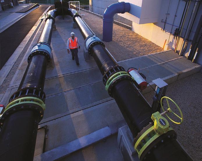
Assistant Editor: Claire Gaynor
Journalists: Elisa Iannunzio
Lauren Butler
Digital Marketing Manager: Sam Penny
Business Development Manager: Rima Munafo
Marketing Assistant: Helena Brace
Melissa Charalambous
Senior Designer: Alejandro Molano
Designer: Aileen Ng
Publisher: Chris Bland
Managing Editor: Laura Harvey
ISSN: 2201-0270
INDUSTRY NEWS
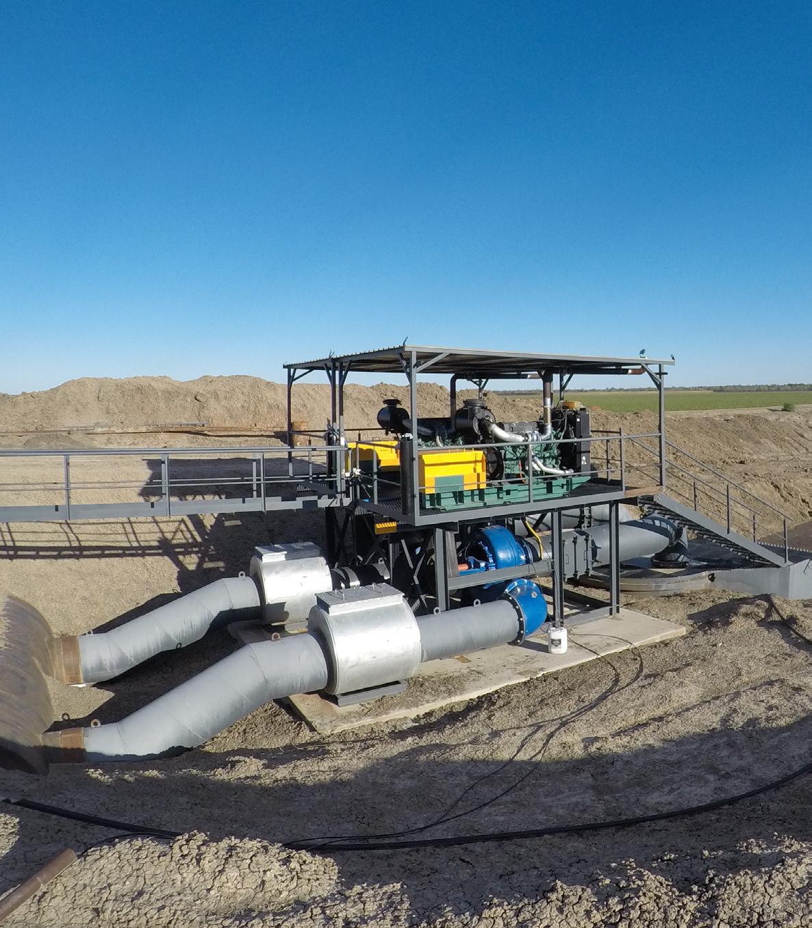
CONTENTS Cover image highlights the power generation feature which looks at the procurement of engines for a power station. This magazine is published by Monkey Media in cooperation with the Pump Industry Australia Inc. (PIA). The views contained herein are not necessarily the views of either the publisher or the PIA. Neither the publisher nor the PIA takes responsibility for any claims made by advertisers. All communication should be directed to the publisher. The publisher welcomes contributions to the magazine. All contributions must comply with the publisher’s editorial policy which follows. By providing content to the publisher, you authorise the publisher to reproduce that content either in its original form, or edited, or combined with other content in any of its publications and in any format at the publisher's discretion.
1 April 2018 – 30 September 2018 Published by Monkey Media Enterprises
4,706
NEWS Contract awarded for TasWater capital works 6 Caloundra sewerage network upgrade complete 6 Tenders for Longford sewage treatment plant upgrade being assessed .. 7 $500 million to boost regional water infrastructure 8 Hiding HVAC and water treatment facilities in a Barangaroo basement 10 Ammaroo Phosphate Project gets the green light ................................. 12 PIA NEWS PIA looks towards the future in 2019 ....................................................... 14 PIA
NEWS New range of EN733 pumps: world leading performance ...................... 18 On a crusade to create the best layfat hoses 20 The new DryWet sewage pumps set to change the market 22
MEMBER
Polymer vanes last three times as long in vacuum rotary pump 24 Gorman-Rupp pumps selected at Southern Meats ................................ 25 High performance motors for energy-efcient pumping 26 A new engine for sustainable farming 28 Highly durable Sectional Panel Tanks available at Masterfow ................ 30

Ask
5 www.pumpindustry.com.au pump industry | Summer 2019 | Issue 26 pumpindustry STATE OF THE INDUSTRY Keeping up in a changing landscape: State of the Industry 2019 32 OIL & GAS Upgrading general purpose steam turbines - Part 2 40 VALVES Waterhammer: causes and variables 48 System simulation as a troubleshooting tool ............ 50 POWER GENERATION Procuring engines for the Barker Inlet Power Station .. 52 The pumps and engines powering cogeneration and trigeneration systems 56 FIRE Battery failure risks in fre pumps 60 Complying with fre pump standards ......................... 64 PUMP HANDBOOK Selecting and applying slurry pumps - Part 2 ............ 68
: President’s welcome ..................................................... 2
Regulars
an expert: Valveless fow control with progressive cavity pumps and their usefulness in oil and gas 66 This
and
school: Restarting motor-driven centrifugal pumps after power failure 71 Editorial schedule ........................................................ 72 Advertisers’ index ....................................................... 72
edition of Ask an Expert will look at valveless fow control with progressive cavity pumps and their usefulness in fow control
Oil & Gas applications. Pump
CONTRACT AWARDED FOR TASWATER CAPITAL WORKS
TasWater has selected its preferred contractor to deliver a capital works program to support and develop water and wastewater infrastructure and major regional water projects in Tasmania.
CIMIC Group companies UGL and CPB Contractors, and TasWater, intend to establish an alliance to deliver infrastructure planning, project development and delivery of all capital works across TasWater’s regional asset network in Tasmania, including:
• Water and wastewater treatment plants
• Water networks
• Dams and water storage
• General asset renewal programs
CIMIC Group Chief Executive Ofcer, Michael Wright, said, “The unique combination of UGL’s expertise in the water sector and CPB Contractors’ experience in major project design and construction projects positions us strongly to partner with TasWater to deliver world-class infrastructure to the communities of Tasmania.”
Caloundra sewerage NETWORK UPGRADE COMPLETE
The construction of a new 15m-deep sewage pumping station at Duck Holes Creek in Caloundra, South East Queensland, is complete, signalling the end of a sixyear-long upgrade to the area’s sewerage network.
Unitywater Executive Manager Sustainable Infrastructure Solutions, Scott Barnes, said Unitywater had invested $30 million across fve major infrastructure projects to ensure the area’s sewerage network will meet the needs of a growing population.
“Greater Caloundra is experiencing considerable growth. Upgrading the sewerage network improves its efciency and lowers maintenance costs into the future. Importantly, the new infrastructure minimises the risk of sewage overfows in extreme weather, and tackles odour and corrosion concerns,” Mr Barnes said.
The upgraded sewerage network services Caloundra, Golden Beach, Aura, Pelican Waters, Little Mountain and Bellvista.
As well as the new pumping station at Duck Holes Creek, works have included new sewer mains in central Caloundra, a new odour control facility in Aroona and relining the Kalana Road sewerage main. Along Nicklin Way, between Caloundra and Aroona, a new sewerage pipeline was built using the longest horizontal directional drill of its kind in Australia.
All new infrastructure was expected to be completed and in service by the end of 2018.
pump industry | Summer 2019 | Issue 26 www.pumpindustry.com.au 6 NEWS
TENDERS FOR LONGFORD SEWAGE TREATMENT PLANT UPGRADE BEING ASSESSED
Improvement works on the Longford sewage treatment plant are one step closer, with TasWater assessing tenders for the design and construction of an upgraded plant.
During 2018, TasWater undertook an early contractor involvement process where potential contractors assisted to workshop design solutions to the unique issues facing the sewage treatment plant.
TasWater said this was the most appropriate, innovative and collaborative method to get a ft-for-purpose solution, and will enable improvement in both the quality of treatment and odour management.
The successful contractor is expected to be awarded the contract in early 2019. Construction is expected to start in late 2019 after a comprehensive design phase.
“This is a complex project, and it’s crucial we get it right from the start,” TasWater Senior Project Manager, Rennie Brown, said.
“It is a comprehensive process, but it is also an opportunity to make sure we are getting the best outcome for all stakeholders, TasWater and the environment.”

The upgrade is designed to accommodate a mix of domestic waste and trade waste from Longford, including waste from the JBS livestock processing facility, and will improve the environmental and odour impacts from the site.
“We understand the community remains concerned about odours, which may persist from time to time until the new treatment plant is commissioned in late 2020,” Mr Brown said.


7 www.pumpindustry.com.au pump industry | Summer 2019 | Issue 26 NEWS PROTECT YOUR PLANT & PERSONNEL Arc Flash Protection PGR-8800 Ultra Fast (1msec) light detecting relay to minimize Arc Fault damage to plant and personnel. Earth Leakage EL731 Wide frequency band (DC-6kHz) earth leakage detection for variable speed drive applications (AS2081:2011 compliant). 6/8 Selkirk Drive, Noosaville, QLD 4566 P.O. Box 1965, Noosaville, QLD 4566 T 07 5455 5060 | F 07 5455 5062 E sales@startco.com.au www.startco.com.au Representing Littelfuse Inc Australia & New Zealand.

$500 MILLION
Transformational water infrastructure projects for regional communities could now become a reality, with an extra half-a-billion dollars added to the National Water Infrastructure Development Fund.
Minister for Infrastructure, Transport and Regional Development, Michael McCormack, announced the fund’s increase of more than $500 million will be used to work with state and territory governments to identify and co-fund the construction of new water infrastructure projects across regional Australia.
“This announcement will turbocharge the construction of water infrastructure in regional Australia because our agricultural industries expect it and our communities deserve it,” said Mr McCormack.
Mr McCormack said water is the lifeblood of regional communities, and this historic injection of funds will be a game changer for many communities.
“This funding pipeline represents the single biggest commitment to investment for building water infrastructure across the nation.
“Access to secure and afordable water is critical to the lives of many Australians in regional areas, and investment in water infrastructure is vital to keep Australia thriving, especially during tough times of extended drought.
“Having the right water infrastructure in the right place will provide greater opportunities for new and expanded highvalue irrigated agriculture.
“This is not just about storing water in times when it is dry; it is also about protecting communities through food mitigation in times when it is incredibly wet.”
Minister for Agriculture and Water Resources, David Littleproud, said water means wealth and jobs in the regions.
“As a former rural bank manager, I know the value of a megalitre of water to a rural community,” Mr Littleproud said.
“We’re proud to be delivering water and wealth to rural communities.”
The Fund’s expansion to more than $1 billion, as well as the existing $2 billion National Water Infrastructure Loan Facility program, means more than $3 billion is now available from the Federal Government to support state and territory governments and their project partners, to build new water infrastructure and provide greater social and economic opportunity for Australians.
“From Myalup in regional Western Australia to Queensland’s Rookwood Weir, we believe in dams and water security, and are investing to make it a reality for regional Australians,” said Mr McCormack.
“This announcement is exciting for regional Australians, who understand full well the importance of water storage.”
The expanded funding includes:
$2 million for the North and South Burnett regions (Queensland)
A $2 million commitment has been made for a feasibility study to investigate increasing water supply and security in Queensland’s North and South Burnett regions.
Federal Member for Flynn, Ken O’Dowd, said the study would help to drive economic and social growth in regional Queensland.
“The feasibility study is great news for farmers in the region, as it will examine a range of options and identify solutions to increase water supply that would underpin an expansion of irrigated agriculture, delivering new jobs and economic growth in the North and South Burnett regions,” Mr O’Dowd said.
“Through the National Water Infrastructure Development Fund, we have committed over $426 million to get construction underway on a series of key water infrastructure projects in Queensland.”
$1 million for the Southern Forest Irrigation Scheme (Western Australia)
The government has committed up to $1 million to fnalise the regulatory approvals required for the Southern Forest Irrigation Scheme to progress towards construction.
The approval process will include developing the fnal business case, design and Environmental Impact Statement for the agricultural irrigation scheme situated in the ManjimupPemberton region of Western Australia’s south-west.
“In Western Australia, one benefciary of this $30 million feasibility component will be the Southern Forests Irrigation Scheme, which proposes construction of a dam and supporting irrigation supply infrastructure to reliably deliver 923ML of water annually to support new irrigation in the Manjimup and Pemberton regions, benefting the horticulture, livestock beef and nursery industries,” Mr McCormack said.
Federal Member for O’Connor, Rick Wilson, welcomed the announcement, saying the project — subject to receiving essential planning approvals and detailed design work — stood to generate a number of benefts for the state’s southwest region.
“If constructed, the Southern Forest Irrigation Scheme will increase water availability to our job-producing regional industries and create up to 150 direct jobs, 75 indirect jobs and up to 125 construction jobs during the estimated two-year construction period,” Mr Wilson said.
pump industry | Summer 2019 | Issue 26 www.pumpindustry.com.au 8 NEWS
to boost regional water infrastructure

“Greater water security will provide growers with the confdence to invest in their business to underpin an expansion of high-value irrigated horticulture of up to 1675ha.”
$250,000 for the Coldstream Recycled Water Pipeline (Victoria)
A new commitment of up to $250,000 to help progress the Coldstream Recycled Water Pipeline Scheme in rural Victoria would help it become construction-ready.
Mr McCormack said the $250,000 commitment to the Coldstream Recycled Water Pipeline Scheme would assist with fnalising the project design, regulatory approvals and operational arrangements.
“The proposed Coldstream Recycled Water Pipeline Scheme, located adjacent to the Yarra River between Coldstream and Healesville in Victoria, involves construction of
two Class A water treatment sub-systems, and a pipeline and distribution network to deliver up to 1500ML of recycled water to producers,” Mr McCormack said.
Federal Member for Casey, Tony Smith, welcomed the announcement.
“If built, agricultural production, tourism and seasonal employment relating to food and fbre all stand to gain, helping support our exports such as cool climate wines, strawberry farms, fruit orchards, and livestock,” Mr Smith said.
“Subject to fnalising the project design and operational arrangements, and receiving all necessary regulatory approvals to proceed to construction, the Coldstream Recycled Water Pipeline Scheme is expected to provide businesses covering approximately 1000ha in the region with improved water security and reliability.”
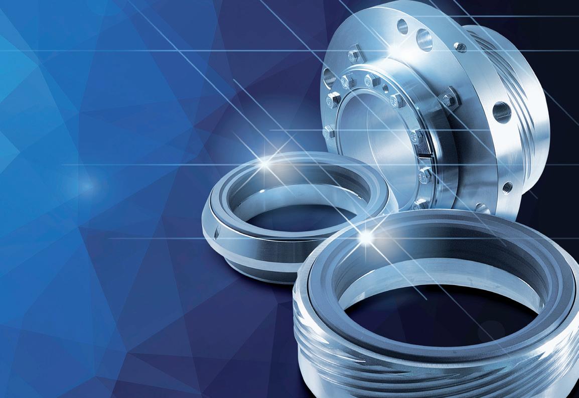
DiamondFace technology: Unbeatable performance for mechanical seals
DiamondFace by EagleBurgmann is the solution for difficult mechanical seals applications. Wherever poor lubrication, partial dry running, abrasive media or electrochemical corrosion leads to high wear, DiamondFace offers the most robust solution.
9 www.pumpindustry.com.au pump industry | Summer 2019 | Issue 26 NEWS
EagleBurgmann Australasia Pty. Ltd. 16 Stennett Road, Ingleburn, NSW 2565 Sydney, Australia Phone: +61 2 9605 0600 info@au.eag eburgmann.com http://eagleburgmann.com.au
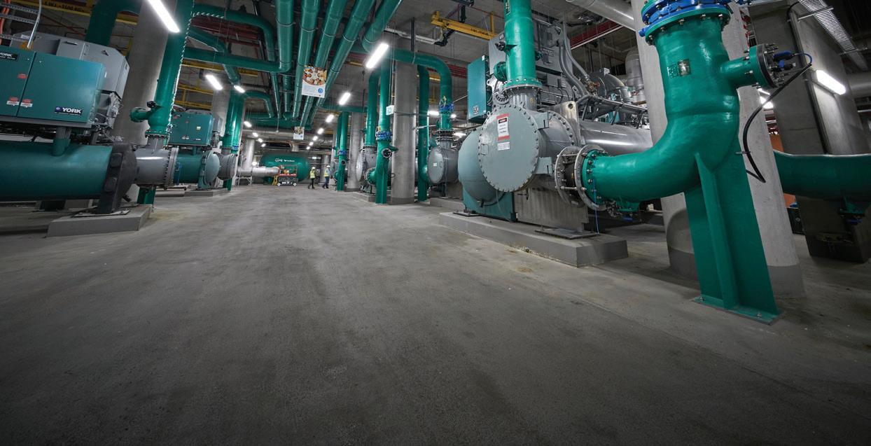
HIDING HVAC AND WATER TREATMENT FACILITIES IN A BARANGAROO BASEMENT
A77,000sqm basement constructed beneath the surface of Sydney’s Barangaroo South precinct is allowing the area to maximise sustainability outcomes while reducing costs.
Containing everything from a cooling plant to water treatment facilities, the basement is a prime example of how to implement less obstructive utility rooms.
James Peterson, Head of Operations for Barangaroo South – Lendlease, was part of a diverse design, development and construction team responsible for bringing the basement to life.
“We wanted to create something that was an example of global operational best practice in terms of its ability to leverage scale to run more efciently, and removing duplication, whilst creating an exciting place for people to live, work and play,” Mr Peterson said.
“Most large commercial buildings around the CBD have poor ground planes because they have to house plant rooms, driveways, loading dock entries and exits, which leaves room for only a cofee shop or two at best. At Barangaroo we’ve taken the plant, access ways, services and systems required for nine buildings into one basement with just two entry points.”
Some key features include:
District Cooling Plant
A typical building’s air conditioning relies on cooling towers on their roof, consuming on average approximately 20,000L of water per day. Rather than following this approach, the design team wanted to utilise the scale and location on the harbour of Barangaroo and developed a harbour heat rejection central district cooling plant in the basement. By using the harbour water this saves the environment approximately 60,000L per day whilst also freeing up the rooftops for solar panels.
Recycled water treatment plant
The plant is capable of creating more water than the precinct uses each day. All black and grey water is taken through mechanical and chemical process to convert used water into high-quality recycled water used for toilet fushing and irrigation. With an ultimate capacity of more than a million litres a day, the plant can process not only used water from the precinct, but also that from neighbouring buildings. This means more recycled water could be exported than the potable water imported.


10 pump industry | Summer 2019 | Issue 26 www.pumpindustry.com.au NEWS
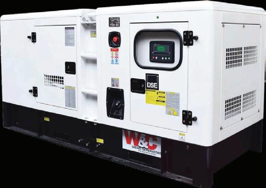
59 Export Dr Brooklyn VIC 3012 Email: sales@wellcross.com.au wellcross.com.au 656 276 AUSTRALIA’S TRUSTED DIESEL POWER AUSTRALIA’S TRUSTED DIESEL POWER Adelaide | Brisbane | Melbourne | Perth | Sydney | Townsville POWERED BY POWERED BY CROSSLEYTM ARE YOU RUNNING YOUR PUMPS WITH GENERATORS? We can custom design generators to suit your pumping and irrigation needs, soft start, VFD or DOL.


INSTALLATION & COMMISSIONING course brisbane


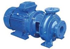
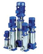
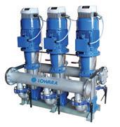
Lowara has an extensive range of pumps and pressure systems suitable for commercial buildings, homes, general industries, agriculture and irrigation.
Reliable, high performance, quality materials, and the widespread Lowara support network make these pumps an ideal selection for your water supply requirements.


11 www.pumpindustry.com.au pump industry | Summer 2019 | Issue 26
FOR MORE EVENTS, NEWS & UPDATES, KEEP IN THE LOOP BY JOINING US ON LINKEDIN @PUMPINDUSTRYAUSTRALIA W H A T ' S O N I N 2 0 1 9 . . . ?
t e c h n i c a l m e e t i n g b r i s b a n e
SEMINARS STAY TUNED! t e c h n i c a l m e e t i n g a d e l a i d e t e c h n i c a l m e e t i n g p e r t h t e c h n i c a l m e e t i n g s y d n e y j u l y a u g u s t o c t o b e r Ph: 1300 4 BBENG www.brownbros.com.au
TECHNICAL MEETING MELBOURNE
HALF-DAY
Call us today to see how we can deliver your pumping solution. DELIVERING PUMPING SOLUTIONS 05/17

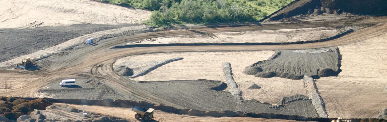
AMMAROO PHOSPHATE PROJECT gets the green light
Aproposed Verdant Mineral Limited phosphate project — including new pipeline infrastructure and borefeld — has been deemed environmentally acceptable by the Northern Territory Environment Protection Authority (NT EPA).
The proposal is to construct and operate the Ammaroo Phosphate Project, located approximately 270km north-east of Alice Springs. Key elements of the proposal include:
• A phosphate mine, processing plant and surface tailings storage facility
• An infrastructure corridor accommodating a 105km rail spur (connecting to the Adelaide to Darwin railway line) and a 137km underground gas pipeline (connecting to the Amadeus gas pipeline)
LEAD CHANGE
CHALLENGE YOURSELF TO ACHIEVE PERSONAL AND PROFESSIONAL GROWTH
Get the business management, leadership and enhanced technical skills you need to progress in your career.
Take the next step and advance your skills through specialized leadership, with a comprehensive 12-month professional master’s degree.
• A borefeld and 12km pipeline for water supply
• Supporting infrastructure
• The realignment of approximately 12km of the Murray Downs Road to bypass the mine site
NT EPA Chairman, Dr Paul Vogel, said the NT EPA identifed potentially signifcant environmental impacts and risks associated with the Ammaroo Phosphate Project and made 12 recommendations to avoid and mitigate these, including regular audits and peer reviews of critical aspects of the project by independent experts, and public transparency of the mine’s water management.
The expected mine life is 25 years, with an additional two years for closure and rehabilitation. The mined-out

pump industry | Summer 2019 | Issue 26 www.pumpindustry.com.au 12 mel.ubc.ca/pump
Integrated Water Management NEWS
pits will be progressively rehabilitated. The mine will have a construction workforce of up to 300 people with an operations workforce of up to 150.
Benefciation (processing) will occur on site, producing up to 2Mt/y of 32 per cent phosphate rock concentrate that will be transported by rail to the Port of Darwin for export.
Water will be sourced from the Georgina Basin carbonate aquifer. The NT EPA identifed the proposed groundwater abstraction of 3.6GL/y as substantial, and paid particular attention to potential impacts on groundwater resources and associated environmental values in the arid zone of the NT where the proposal is located.
The NT EPA’s key recommendations focus on ensuring leading practice in the management of groundwater resources, rehabilitation and closure, and community engagement, in order to provide a high level of confdence that the proposal will meet the NT EPA’s environmental objectives.
In addition to stringent monitoring and mitigation measures, the NT EPA recommended full transparency in relation to the mine’s groundwater abstraction through


stakeholder consultations and public disclosure of all water management plans and annual reports.
Although initial investigations indicate that mined and processed materials will be unlikely to produce saline, acid or metalliferous drainage, the NT EPA recommended a stringent precautionary approach to avoid, minimise and immediately mitigate any of-site efects from the proposed mine.
The NT EPA supports the proposed progressive rehabilitation of the mine, and has made recommendations to ensure that mine closure planning is thoroughly considered prior to authorisation of the proposal and on an ongoing basis throughout the mine life, including appropriate stakeholder consultation and an agreed post-mining land use.
“The NT EPA considers that, subject to the implementation of all recommendations and the commitments and safeguards listed in the proponent’s Environmental Impact Statement, the proposal can be managed in a manner that is likely to meet the NT EPA’s objectives, and avoid signifcant or unacceptable environmental impacts and risks,” Dr Vogel said.

NEWS
13 www.pumpindustry.com.au pump industry | Summer 2019 | Issue 26
PIA
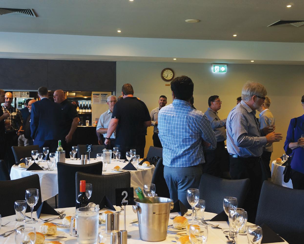
looks towards the future in 2019
Last November, the PIA council and its members gathered in Melbourne for the association's annual general meeting and dinner. Atendees were updated on the association’s activities and achievements over 2018, as well as its plans for 2019 and beyond.
The PIA reported it had been a busy year, with the council working on a number of projects to further standards in the industry, improve knowledge and skills training, and industry collaborations.
A lot of work was undertaken on standards in 2018, with AS/ ISO 9906:2018 Pump Performance Acceptance Test Standard replacing AS 2941 last February. The PIA is also leading a proposal to adopt ISO/ASME 14414:2015 Pump System Energy Assessment as an Australian Standard, and will be voting for the acceptance of the draft AS 2304 Water Storage Tanks for Fire Protection Systems.
The PIA also collaborated with a number of external stakeholders throughout the year with activities, including:
• Collaboration with AMCA to provide support for the new Centre of Excellence being developed at Holmesglen TAFE in Victoria, with work already underway
• Collaboration with the Fire Protection Association Australia (FPAA) on adoption of a AS 2941 fre equipment certifer’s checklist, see page 64 for more details
• Discussions with Standards Australia to be an "International Participant” so PIA can have direct input to the ISO committee in Europe for pump standards
• Chairing the Department of Energy and Environment subcommittee on Minimum Efciency Performance Standards (MEPS) for pumps regulations
pump industry | Summer 2019 | Issue 26 www.pumpindustry.com.au 14
PIA NEWS
Training and seminars
The PIA said a number of training courses and seminars had been successfully held, with the year kicking of with a Technical Meeting held at Regal Beloit in Melbourne in March.
In May, a one-day efciency seminar was held in Melbourne looking at energy efciency and savings in pumping systems. Around 30 pump professionals attended the event to hear presentations from ten industry experts and government personnel. Attendees heard about the latest developments on the impacts of pumping systems on energy and the environment, energy efciency policies and planned legislation, and technical and commercial advances made in the application and penetration of energyefcient pumping systems.
The seminar was well-received by attendees, so two half-day energy efciency seminars were held in September in Brisbane and Sydney.
Further Technical Meetings were held throughout the year in Brisbane and Adelaide in July and September, and an Installation and Commissioning Course was held at KSB in Brisbane with eight certifed pump professionals graduating.
Looking towards the year ahead
The council announced the PIA is looking towards the future, with activities in 2019 set to further the reach of the association, and provide more opportunities for members and non-members to further their skills and learn about changes to the industry.
A key objective of the council moving forward is to increase membership, with plans now underway and upcoming to achieve this, including:
• Introduce digitalisation, such as live streaming of AGM, e-learning, LinkedIn, Facebook, and email signatures for current members
• Include Pool (Domestic and Commercial), Irrigation, Rural and Domestic Sectors to the PIA
• Better use of website for communication and payments
The PIA is also looking to continue providing opportunities for training and seminars on topics of interest to the industry, as well as improvements to qualifcations. Plans include:
• Formalisation of Selection, Sales and Installation qualifcations, such as generic VET qualifcations, which will be transferable to all employees at all levels. Has acceptance with IAL, ABCB, Master Plumbers and industry
• Continue energy efciency seminars

Dr Margaret Beavis from 2017 Nobel Prize winning organisation International Campaign to Abolish Nuclear Weapons (ICAN) gave a thought-provoking and debate-inducing presentation about the work being undertaken by the organisation to promote adherence to and implementation of the United Nations nuclear weapons ban treaty.

15 www.pumpindustry.com.au pump industry | Summer 2019 | Issue 26 PIA NEWS
Greg James and Ken Kugler.
Les Boelckey, Lynne Sanders and Keith Sanders.
• Organise additional meetings on changes to standards
• Organise and identify potential speakers who will be of interest and beneft to members
• Continue to hold regular meetings in capital cities for members
• Continue to organise seminars and workshops in capital cities on technical topics such as energy efciency, fre pump installations, general pump technology and to increase industry awareness of Australian capabilities for pump equipment
• Organise training programs to service the needs of members, including the new PIA Installation and Commissioning course, and promotion of the BPMA and HI training programs
There will also be some changes to the PIA moving forward, with key council positions being updated and expressions of interest sought, and portfolios will be allocated to each councillor.
Along with upcoming changes, the council will continue liaising with industry organisations and government departments to promote cooperation between industries, and improve standards.


16 pump industry | Summer 2019 | Issue 26 www.pumpindustry.com.au PIA NEWS
Alan Rowan, Anant Yuvarajah and Ashley White.
Nick McNamara, Mark Alexander and Ron Astall.
Listening to the needs of the members
The PIA aims to help its members grow and operate successful, sustainable businesses through representation, promotion, information and research. In order to do this, it needs feedback from members so it can provide them with the information and knowledge they want and require.
In late 2018, an anonymous online survey was conducted which will help shape activities in the year ahead, in particular training and seminars. The council strongly encourages all members to take part in such surveys in the future or to email feedback or suggestions for topics and speakers to the council directly, to ensure you are getting the most beneft from the association.


TO EXACTING STANDARDS


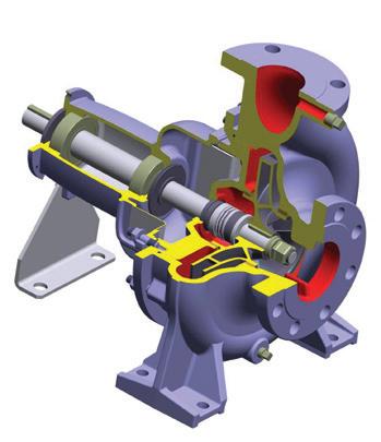
The new BNA pump ensures compliance with API 676 and API 682 while reducing costs in petrochemical applications.
YOUR BENEFITS
676 and API 682
www.pumpindustry.com.au pump industry | Summer 2019 | Issue 26 17 PIA NEWS
SEEPEX Australia Pty. Ltd. info.au@seepex.com www.seepex.com
API
compliant Extremely robust design High containment pressure and corrosion resistance Simple integration into piping systems Non-welded casing means reduced documentation and fewer inspections Shorter lead time High operational safety Act now to experience the benefits of this API pump for yourself.
API 676 PUMP
PIA Vice President, John Inkster, gave an overview of PIA activities over 2018.
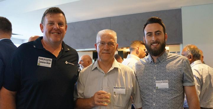
Cameron Shaw, Peter Kropf and Jaydan Steel.
Je
ff Greely and Malcolm Eyre.
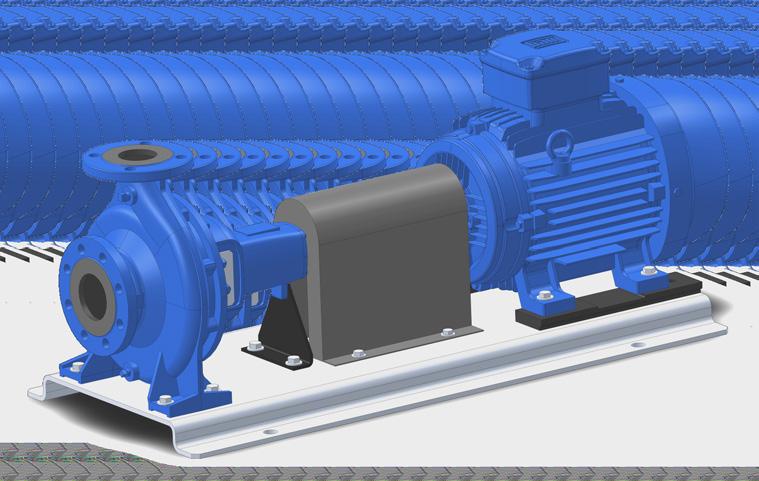
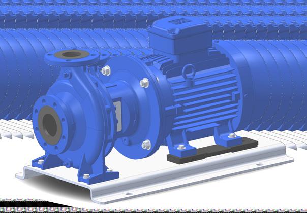
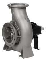
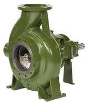
New range of EN733 pumps: WORLD LEADING PERFORMANCE
As a major manufacturer of industrial pumps to JIS and API610 standards, Ebara Corporation has embarked on a globalisation of its range of pumps for the world market. This includes the introduction of a range of industrial pumps to European EN733 standards and a new range of vertical multistage pumps.
Ebara Corporation (Japan) has recently released its new global range of EN733 standard end suction centrifugal pumps.
Utilising the most advanced hydraulic computer design software available, Ebara engineers in Japan have been able to improve and increase the pump efciencies of the new GS range above most other available pumps of similar design and standard on the global market.
The new Ebara GS range of EN733 standard pumps are manufactured in component form at Ebara Corporation Japan owned and managed factories in the Asia Pacifc region with fnal assembly of market range models undertaken by skilled tradesmen at Ebara Pumps Australia’s Melbourne facility.
A 16 bar rated pump — the new GS — will be available in both long coupled and close coupled versions (GSD) and will be available for release in Australia early 2019.
About Ebara Corporation
Ebara Corporation was founded in Japan in 1912 as a manufacturer of pumps. Today, as a group, it consists of more than 70 companies in six continents with a workforce of more than 11,000 people, and with company owned and Japanese managed factories in eight countries covering four continents.
The huge scale of production and distribution is matched by a constant commitment to research, development and design of new products and the
modern technologies for manufacturing them. Ebara products have gained a worldwide reputation for their technology and quality.
Contact your local Ebara dealer or Ebara Pumps Australia for more information.
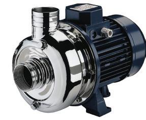
Two of the more popular models that are stocked in Australia are both solids handling pumps. For more details contact us at Ebara Pumps Australia or visit our website.
MODEL DWO
Stamped stainless steel pumps with open impeller
Maximum 19mm passage size
50mm discharge
1.1 to 1.5kW - 1 phase
1.1 to 3.0kW - 3 phase


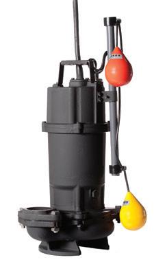
MODEL DVS
Cast iron submersible pumps with semi vortex impeller
32 to 56mm passage size
(Depending on model)
50 and 80mm discharge
0.4 to 0.75kW - 1 phase
0.75 to 3.7kW - 3 phase
Manual or automatic


18 pump industry | Summer 2019 | Issue 26 www.pumpindustry.com.au
PIA MEMBER NEWS | PARTNER SOLUTIONS
ON A CRUSADE TO CREATE THE BEST LAYFLAT HOSES
Crusader Hose was the first fire hose manufacturer in the Australian market, having created its first hose in 1985. Initially comprising the fire hose division of Wormald, the company has grown to create one of the most sought-afer range of products suitable for application across the agricultural, industrial and mining industries.
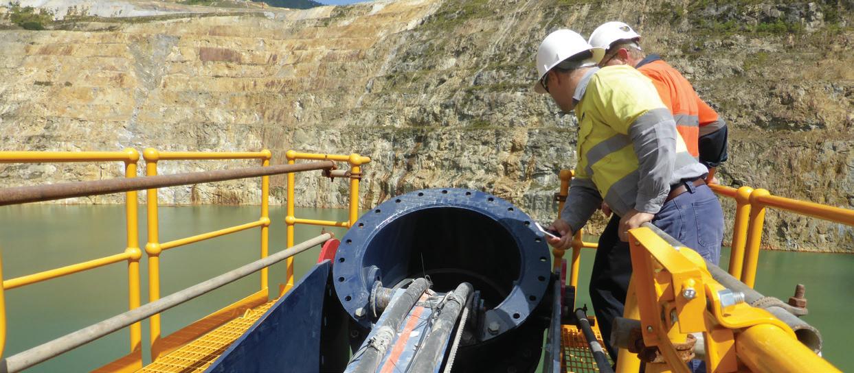
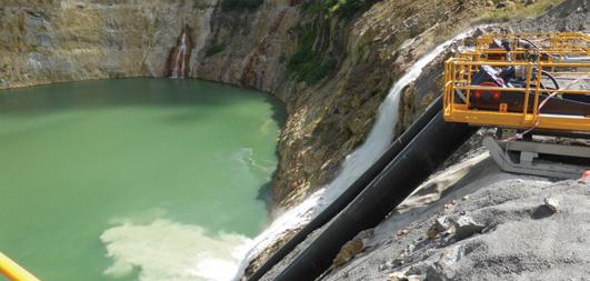
By 1990, Crusader Hose had developed the bore water pumping hose series Flexibore, which was made for mine dewatering applications. The company’s existing weaving and extrusion machinery meant it was ready to produce its bore water pumping fexible riser.
Crusader Hose National Sales Manager, Daniel Seow, who has previously held senior management roles in the electronics industry, said, “Crusader Hose focused on its ability to manufacture everything that was layfat — all the fttings, the winders, the systems. That’s what we do, and we do it to the best quality possible.”
At the time, only one international brand supplied layfat hoses to the Australian market, but at a premium price — meaning Crusader Hose could be competitive.
“Our customers wanted to support an Australian-made product. That’s when we went about developing a hose that is made for Australian climate and conditions,” Mr Seow said.
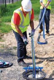
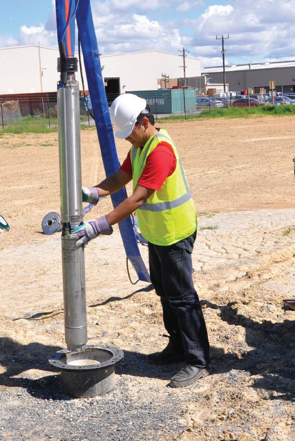
Making bore water retrieval simple
Bore water retrieval can be a difcult process, with use of rigid pipes a thing of the past. That’s why Crusader Hose developed its layfat hose.
After listening to feedback from its target market, Crusader Hose presented the Flexibore 250 series fexible riser hose, a high-pressure hose that can go up to 250m underground.
“I thought a hose was just a hose. But there’s so much more to it,” Mr Seow said.
“If we’re going to go down 250m, the hose must have the tensile strength to be able to handle all that weight.
“The key to the layfat hose manufacturing process is building the right jacket for the right pressure, and precision extrusion with proper quality checks.”
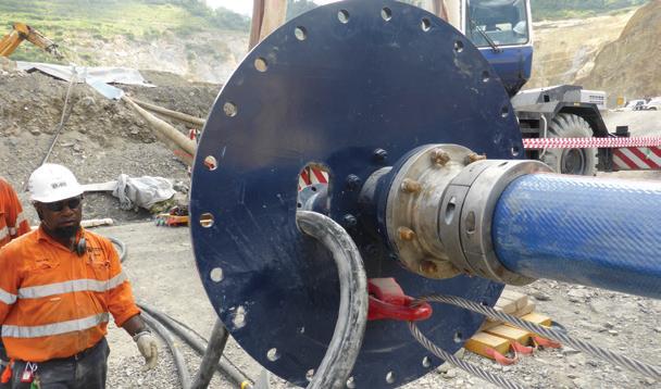
Crusader Hose crafted these resilient hoses by integrating thermoplastic polyurethane into a woven textile fabric of hightenacity polyester. This heavy-duty internal fabric creates a hose that is fexible, yet has the strength to sustain the weight of a submersible pump.
The Flexibore 250 series is designed to withstand highpressure bore water pumping, unlike many rigid pipes. The movement of the hose during pumping also prevents the build-up of iron bacteria inside.
“Because of how strong it is, the use of a safety cable to secure the pump is almost negligible,” Mr Seow said.
Designed for practicality
Users can be rest assured that they’ll get great value with the Flexibore 250 series hose, as the hose swells by up to 15 per cent, pumping more water out for greater efciency and an excellent fow rate.
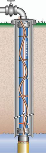
Each part of the design has been carefully thought through — from the loops at one-metre intervals to thread your power cable through, to the customised stainless couplings designed to work with the whole Flexibore system.
Crusader Hose is also happy to create the perfect hose for your individual needs, with diferent lengths and types available.
“We are able to customise our hose to user requirements, and we pride ourselves on our customer service,” Mr Seow said.
Unlike rigid pipes, the layflat style of the hose means it can easily be transported to and from mine sites, saving time and money.
And, most importantly, Crusader Hose always puts safety frst: each hose must also pass a hydrostatic pressure test before leaving the factory.
With all of these features incorporated for ease of use, the design of the Flexibore 250 series hose truly has the customer front of mind.
20 pump industry | Summer 2019 | Issue 26 www.pumpindustry.com.au
PIA MEMBER NEWS | PARTNER SOLUTIONS
FLEXIBORE FLEXIBORE


Crusader Hose Pty Ltd 22 Industry Place, Bayswater, VIC 3153 Australia Telephone: +631 3 9720 1100 www.crusaderhose.com.au For any enquiries, email sales@crusaderhose.com.au
NO IRON BACTERIA BUILD UP NO CORROSION Flexibore Coupling Flexibore Hose Power Cable Power Cable Strap Borehole Pump PUMPING EFFICIENCY & COST SAVING EASY STORAGE, HANDLING & TRANSPORT QUICK AND EASY INSTALLATION & RETRIEVAL Customised Layflat Hose Systems CRANE ON TRUCK ON CRANE OVER A ROLLER WALK IN BORE PUMP BORE PUMP THE SYSTEM OF CHOICE FOR GROUND WATER PUMPING THE SYSTEM OF CHOICE FOR GROUND WATER PUMPING If it’s a bore, think FLEXIBORE!
The new DryWet sewage pumps set to change the market
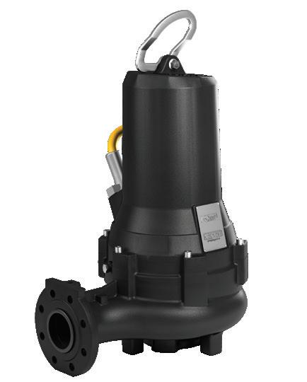
Thanks to its dedicated research and development division, Caprari—headquartered in Modena, Italy—is able to ofer its customers products with high efciency and distinctive performance. Each new pump is designed be efcient and technologically advanced, ensuring they meet market demands.
To meet the needs of end users who are increasingly concerned about energy savings and operational costs, as well as to anticipate changes to the European Union’s Ecodesign Directive, Caprari has released a new pump range which has unique and revolutionary features for dealing with wastewater—the K + Energy range.
The new K + Energy range of pumps is designed with IE3 Premium Efciency motors, as defned in EC Regulation 640/2009 specifc for surface motors, to ensure optimum efciency. The careful selection of the best performing materials and cooler motors ensure total reliability of operation, even in critical applications.
A turning point in pump design
The brand new K + Energy range represents a turning point due to its innovative and unique "DryWet" system which keeps the pump cool.
The "DryWet" cooling system is simple and reliable, can be easily activated, and is standard for the full
Caprari has launched an innovative new product with an exclusive patent, that is set to be a turning point in wastewater pump design. The new K + Energy range of pumps take reliability and efficiency to a new level, and captures Caprari’s core business to find new efficient solutions for water management.
There are numerous features of the new DryWet pump to ensure reliability over time and operational performance, including:
• Configuration
» Anti-sedimentation system on the suction side
» Fibre-cutting system on the back impeller to protect the mechanical seal
» Blades on the back have the dual advantage of cleaning the area for seal protection, as well as compensating for axial thrust to protect the bearings
range. Customers are able to use a single model for both submerged applications and in dry chambers.
In addition, the "DryWet" system has two important advantages: it does not require additional maintenance and does not absorb energy, allowing the pump to perform at its best. The K+Energy range is also available in an explosion-proof version with ATEX and IECEx (North America explosion protection directive) certifcations.
Another interesting feature is the conductivity probe in the oil chamber— also available in the ATEX version (patent pending)—which is unique to the K + Energy range.
If the frst seal is damaged, an alarm signal is immediately sent to the panel so that repairs can be carried out before the pumped liquid passes the barrier created by the second seal. This ensures the electric motor is always protected.
The connector—supplied as standard on all K+Energy models—allows the pump to be disconnected without having to remove the cables from the panel, before transporting and reconnecting them. This signifcantly reduces intervention time and guarantees the safety of operations.
The large precision cast stainless steel handle is robust, ensuring easy handling of the pump and allowing operators to easily recover it when submerged.
» It has amongst the widest passages for real anti-clogging
• Double mechanical seal
» Independent and nonproprietary mechanical seals (no cartridge system)
» Less oil is required to ensure low environmental impact and ease of disposal
» Disassembly of mechanical seals has been improved so they can be replaced on the pump side, leaving the motor safe
• The gasket is between pump and coupling foot to ensure perfect sealing between components with no head loss over time
Caprari, with its new K + Energy range and exclusive "Dry Wet" system, presents itself as the leading company in advanced solutions for water management and meeting customers needs.
22 pump industry | Summer 2019 | Issue 26 www.pumpindustry.com.au PIA MEMBER NEWS | PARTNER SOLUTIONS


Designing the future with highly appreciated and advanced solutions for Industrial Applications Pumps and electric pumps able to raise primary process water and waste water. ENERGY | METAL INDUSTRY | PAPER INDUSTRY | FOOD & BEVERAGE YOUR RELIABLE PARTNER IN INDUSTRIAL APPLICATIONS EXPERIENCE SINCE 1945 www.caprari.com |
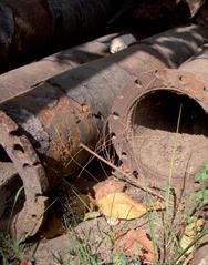
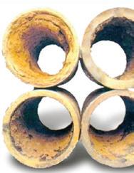
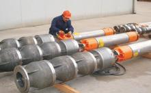
Vanes made of the bearing polymer Hitemp 150 have lasted three times as long as traditional vanes in servicing company Septic Tanks’ vacuum rotary pump, a Broom B35.
The pump is used to create a pressure diference that sucks up the waste liquids from septic tanks.
Ideally, the pumps involved in such operations should not come into contact with sewage. However, where septic tank pumping is not monitored continuously, overfow from the transport truck can make its way to the pressure vessel and on to the vacuum rotary pump.
The vanes in these pumps thus need to be cleaned.
In addition, the vanes need to be able to operate at high temperatures, since the pumps can overheat due to operation for long periods.
Armed with information about vane operating requirements — when the original laminate vanes in Septic Tanks' Broom B35 pump needed replacing as frequently as every six months — the waste sector servicing company turned to Vesconite Bearings, the maker of various polymers, for a solution to this
POLYMER VANES last three times as long in vacuum rotary pump
unique operating environment.
Vesconite Bearings technical sales consultant Phillip de Villiers recommended Hitemp 150, an engineered polymer that is wear resistant and can withstand temperatures of up to 150ºC.
This material will not delaminate as does the original equipment manufacturer supplied material, a thermosetting phenol formaldehyde resin that impregnates layers of cotton to produce a hard synthetic plastic.
The trial result has been impressive; Hitemp 150 did not delaminate, unlike its competitor, and it was resistant to overheating.
In addition, the new polymer vanes coped well with the frequent pump cleaning that was required when waste material accidentally entered the pump.
Septic Tanks owner, Charl Neuhof, is also pleased that the Hitemp 150 vanes continue to operate after a year and a half, while the phenolic alternative had to be replaced after six months.
Moreover, he is enthusiastic about the reduced maintenance costs that are associated with the product, which can

be cleaned in-situ,unlike the previous variety of vanes that had to be removed prior to cleaning because of their high levels of swelling when exposed to water.
Since testing of the B35 vacuum rotary pump vanes has gone well, Mr Neuhof plans to replace the vanes on his feet of truck pumps as they fail.
His four trucks are used in the Johannesburg North, Pretoria, Hartebeespoort and Brits areas of South Africa, with three out on the road daily, each carrying six 6000 litre loads of waste material a day.
The fve vanes that were employed in the B35 pump measured 35mm by 6mm by 330mm and had chamfered edges, but vanes for the other pump models that will be introducing the Hitemp 150 vanes will have diferent dimensions.
Depending on the size required, the vanes will be cut from extruded or moulded Hitemp 150 plates, with Vesconite Bearings able to machine the vanes as a result of the company’s extensive machining capability, including more than 65 computer numerically controlled lathes and machining centres.
Mr de Villiers is excited about the use of Hitemp 150 engineered polymer vanes in vacuum rotary pumps employed in the septic tank servicing industry.
“Septic tanks are an important and reliable means of disposing of and treating household wastewater in South Africa and globally,” Mr de Villiers said.
“The servicing of these tanks is equally important, as good hygiene practice requires that they be pumped out every year.”
pump industry | Summer 2019 | Issue 26 www.pumpindustry.com.au
24 INDUSTRY NEWS | PARTNER SOLUTIONS
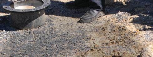
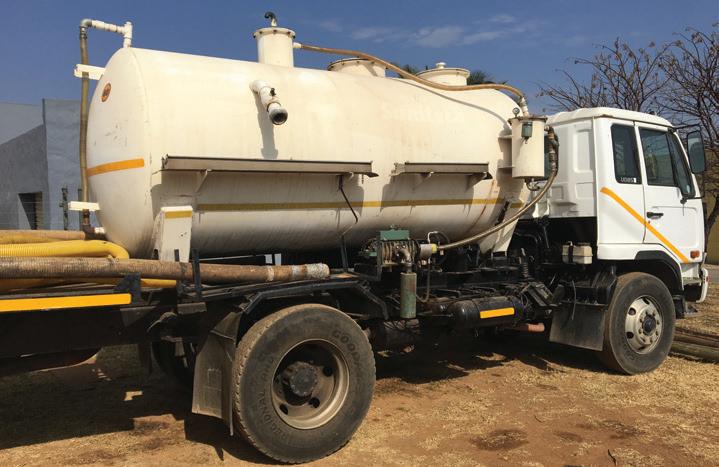
The septic tank cleaning vehicle
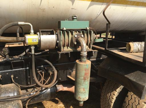
The Hitemp 150 vane
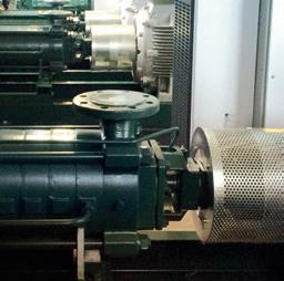
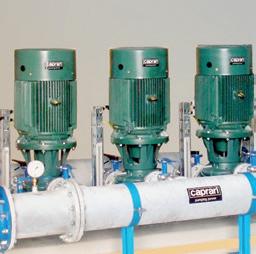
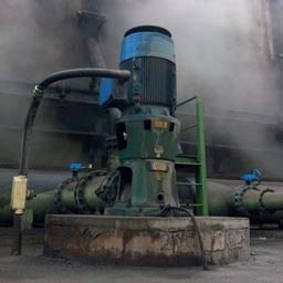
A view of the pumps that the vanes are used in
GORMAN-RUPP PUMPS
SELECTED AT SOUTHERN MEATS
Southern Meats is a hi-tech sheep and lamb processing facility strategically located just south of Sydney where it has access to sheep grown in the healthy environment of NSW’s Southern Highlands region. It prepares quality meat for the local market and global exports using hi-tech automated equipment in its slaughtering, boning, chilling, freezing and rendering facilities.
In line with its quality approach to processing, the plant did not want its operators spending needless time attending to unreliable equipment in its wastewater treatment systems. So when it went looking for a dependable and reliable wastewater pump to deliver 50L/s plus to its treatment area, the plant looked no further than Gorman-Rupp.
Gorman-Rupp is the world leader in self-priming pump technology, particularly in wastewater pumping applications. Being able to mount the pump at ground level (and not in the wet well) means the pumps are safer and more conveniently accessed by operators. Additional safety features built into the pump are designed to protect operators and the pump from damage.
By using self-priming pumps, asset owners don’t need to buy rated lifting chains or have the yearly burden of inspection or replacement of these as they would need if using submersible pumps. And because wet well lids remain closed, the need to have fall protection equipment such as anchorage points, body
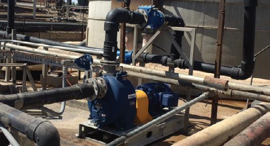
support, connectors and descent/rescue equipment is greatly reduced — some of these items requiring annual trips back to the manufacturer for service/inspection.
Plant Engineer Mick Speering is very pleased with his purchase and is happy to recommend Gorman-Rupp pumps to anyone wanting a quality wastewater pump.
For more information on Gorman-Rupp pumps, email Hydro Innovations at info@hydroinnovations.com.au.

www.pumpindustry.com.au pump industry | Summer 2019 | Issue 26 INDUSTRY NEWS | PARTNER SOLUTIONS
25
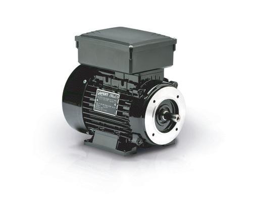
High performance motors for energy-efcient pumping
The world market for industrial IE4 low voltage motors was estimated to be worth $114.7 million in 20132, with nearly 260,000 units shipped1. IE4 motors sold for pumping applications has been the fastest growing and highest valued IE4 motor application segment, generating $31.4 million in revenues with over 90,000 units shipped in 2013. This market has continued to grow strongly and its steady growth is expected to continue into 2019.
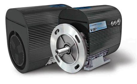
Lafert Electric Motors, one of the world's leading manufacturers of IE4 and IE5 high performance (HP) electric motors, has won the contract to supply its HP motors to two of the largest pump manufacturers in the US.
These multi-million dollar contracts will ensure Lafert remains one of the most important IE4 and IE5 motor manufacturers for the foreseeable future.
This uniquely engineered product combines the electrical design of brushless servo motors with the mechanical design of AC induction motors. The result is a compact motor primarily designed for the HVAC and pump industries where there is an emphasis on reducing the operating cost or weight, and size of the motor.


fficiency values referred to the variable torque requirement (pump application)
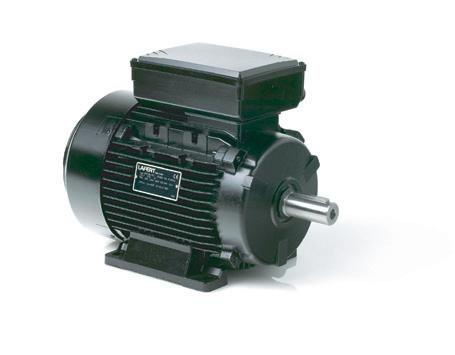
Lafert HP motors have an increased starting torque when compared to a standard 3 phase induction motor. The reason for this is because of the permanent magnets which also assists the current draw at reduced speeds, so when motor speed is decreased, the current drops away signifcantly to virtually no current draw at all.
Peter Harrington, Managing Director of Lafert Australia, said, "Our goal is to assure our clients and partners that the technology developed by Lafert is the right choice for today and, more importantly, for the future. For Lafert, it is essential to meet the demand for improved levels of efciency in view of an increasingly green-oriented market.”
The high operating efciency ofered by Lafert's PM Synchronous Motor leads to lower electricity consumption costs. The uniquely efcient design also improves the life of this motor, thereby reducing potential down time and reftting costs. The motor meets the IE4 efciency class at all operating speeds, making it one of the most efcient electric motors available in the European market.

Horizontal and Vertical pumps
Horizontal pumps Vertical pumps
Sensorless PM Synchronous Motor
• Rated speed: 1500-1800-30003600-4500 rpm
• Rated power: 0.55 to 30 kW
• Frame sizes: 71 - 90 - 112 - 132
• CASCADE mode (CANBus or RS485)
Input/output signal for pressure transducer
Sensorless PM Synchronous Motor
• Energy saving and optimised flow/pressure control
• Variable speed grants more control modes
• Continuous operation increases comfort
Possibility to apply cascade control
pump industry | Summer 2019 | Issue 26 www.pumpindustry.com.au 26 INDUSTRY NEWS | PARTNER SOLUTIONS
1 The World Market for IE4 low-voltage Motors - 2015 Edition 2 Ibid HPS stand alone motor 3000 min-1
AC motor
motor 5.5kW 90 100 80 IE2 + FC IE4 + FC (HPI) IE3 + FC 60 70 Eff [%] 40 50 0 500 1000 1500 2000 2500 3000 3500 Speed [min-1]
E
5.5.kW vs HPI
8 6 4 2 0 0 500 1000 2000 3000 2500 1500 HPS71 3000 rpm 0,75 kW HPS71 3000 rpm 1,1 kW HPS71 3000 rpm 2,2 kW HPS71 3000 rpm 1,5 kW
3000 rpm Num
Torque HPS71

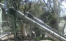
A NEW ENGINE FOR SUSTAINABLE FARMING
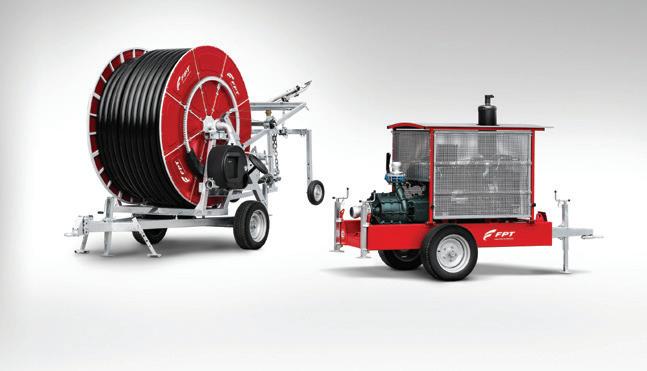
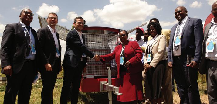
FPT Industrial headed up a major event on 26 September themed ‘A new engine for sustainable farming’. In collaboration with FPT Industrial OEM Idrofoglia, a custombuilt IPU (Irrigation Power Unit) system was designed and manufactured as part of a new water management project in Kenya. The advanced system was donated to Jomo Kenyatta University of Agriculture and Technology (JKUAT) in Nairobi, at this inaugural event.
The FPT Industrial water management project in Kenya has many sustainability targets, including the successful training and support of new entrepreneurs in the agriculture segment, and full technical collaboration with JKUAT. Around 40 ffth-year engineering students at JKUAT will begin courses and use the donated IPU system for training and education.
Federico Gaiazzi, Head of Global Marketing at FPT Industrial, said, "We are proud to support the project, ‘A new engine for sustainable agriculture’. It represents an opportunity for us to further afrm our values and our commitment to supporting training programs for young people and new generations.
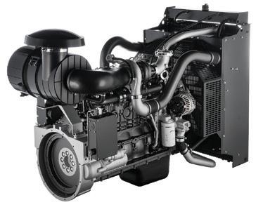
"For this purpose, we decided to donate a complete product, consisting of a motor pump and the related irrigation system. We have chosen this IPU, equipped with an FPT F32 engine because it is a compact and fexible solution that ofers high performance with low operating costs. Today, we give the Jomo Kenyatta University of Agriculture and Technology in Nairobi an engine capable to contribute to a more sustainable future, drawing a unique opportunity to contribute concretely to promote the technological development of Kenya.”
The event ‘A new engine for sustainable farming’, involved corporate presentations by all the major stakeholders, including CNH Industrial,
FPT Industrial, the Milan Center for Food Law and Policy (MCFLP), the E4Impact (Entrepreneurship 4 Impact) Foundation, and respective authorities. In addition, the event focused on the custom-built IPU, with a walk-around scheduled as part of the proceedings.
Comprehensive training sessions were also planned to take place between September and October, and included 40 hours of training provided by FPT Industrial, both in the feld and in the classroom. Additional in-class training was delivered by the E4Impact Foundation and MCFLP.
E4Impact is an initiative launched in 2010 by ALTIS — the Graduate School of Business and Society at the Università Cattolica del Sacro Cuore (UCSC) in Milan, Italy — with the objective of training entrepreneurs in the developing world to support the start up and growth of their businesses. In Kenya and various other African countries, E4Impact ofers an MBA in Global Business and Sustainability to provide active and aspiring entrepreneurs with results-oriented education, coaching and interaction with the local business community and access to potential investors.
MCFLP was frst established in 2015. The association collects and stores legislative materials and documents regarding the right to food and nutrition,
with the ultimate goal of raising awareness on these important issues.
Both E4Impact and MCFLP lay the foundations for future development, which is why they joined FPT Industrial’s water management project in Kenya. The successful cultivation and harvesting of crops on a reliable and repeat basis could experience a huge boost through the application of technology, such as irrigation systems. In combination with the right education and training, it is hoped that signifcant strides forward will be achieved.
IPUs from FPT Industrial are highly capable systems that comprise an engine, frame, subbase, industrial clutch, cooling package, starting battery, exhaust mufer and industrial power take-of unit. Also included is a fuel tank and connection for DEF (Diesel Exhaust Fluid – AdBlue), and an ATS system rack mounted to the top of the body panelling. With regard to irrigation, the IPUs can be used in horizontal and vertical pump installations, as well as for center-line pivot systems. Further uses include systems that transfer water from rivers into defooding channels and feld drainage. Beyond stationary applications, FPT Industrial’s IPU technology also has many mobile uses in the agriculture sector, including for machinery such as sprayers and windrowers.
pump industry | Summer 2019 | Issue 26 www.pumpindustry.com.au 28
INDUSTRY NEWS | PARTNER SOLUTIONS
The FPT Industrial IPU system for Jomo Kenyata University of Agriculture and Technology
At the center, Federico Gaiazzi, Global Marketing Manager of FPT Industrial, shaking hands with Victoria Wambui Ngumi, Vice Chancellor of the Jomo Kenyata University of Agriculture and Technology of Nairobi

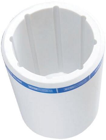
HIGHLY DURABLE SECTIONAL PANEL TANKS AVAILABLE AT MASTERFLOW
Masterflow Solutions is a specialised supplier of customised equipment to heating, ventilation and air conditioning industries throughout Australia. A range of Sectional Panel Tanks made of highly durable material is now available.
Masterfow Solutions stocks a range of GRP Sectional Panel Tanks made from sheet molding compound. Created using hydraulic hot presses under high temperature, these tanks are made to withstand high pressure conditions. The panel tanks demonstrate excellent resilience to corrosion thanks to their stainless steel interior and plated steel fnish.
The Sectional Panel Tank can be utilised in several applications and can be installed however tight or difcult the surrounding environment is. The company also ofers a pre-insulated panel to reduce heat loss during system operations. Because of the sectional design, tanks can be constructed in irregular shapes to go around pillars and other obstructions.
Masterfow’s panels and their related parts conform to international water quality standards, namely:
• Certifcate of Water Regulations Advisory Scheme (UK)
• Certifcate of Productivity and Standard Board Water Pressure Test
• ISO9001:2000 Quality Assurance Certifcation
• FDA Certifcation
Masterfow Panel Tank features and benefts
Following are some features of the Masterfow Sectional Panel Tank:
• Hygienic – Masterfow’s panel tanks are completely opaque. This prevents any light passing through its panels. Opaque panel tanks also hamper the growth of algae and other microorganisms.
• Water tightness – Masterfow water tanks have a self-sealing feature that eliminates the possibility of panel separation and prevents leakage.
• Complete Drainage – Masterfow

TOP QUALITY VALVE KNOWLEDGE WITH SUPPLY AT AN AFFORDABLE PRICE
bottom panels concave drain panel design allows complete and efcient drainage, which is great for maintenance inside the water tank.
• Safety of water pressure – Unlike other tank types where water pressure can loosen the joints, breaking the seal and allowing water to leak out, Masterfow Convex bottom panel tank seals will hold the water pressure created by flling joints preventing leakage.
About Masterfow
Masterfow Solutions is an established provider of customised equipment for storing, pumping and fltering fuid. The company strives to supply the most comprehensive range of quality products and innovative specialty solutions throughout Australia.
Want to know more about Masterfow Solutions – visit www.masterfow.net.au
30 pump industry | Summer 2019 | Issue 26 www.pumpindustry.com.au (02) 6374 2808 133 Mayne St, Gulgong, NSW 2852 mail@midwestvalves.com.au www.midwestvalves.com.au Midwest Valves & Controls is your one stop shop for the valves, poly fittings, hoses and pumps that complete your project.
INDUSTRY NEWS | PARTNER SOLUTIONS
THE ASM V-SERIES IS PRIMED AND READY TO PUMP.
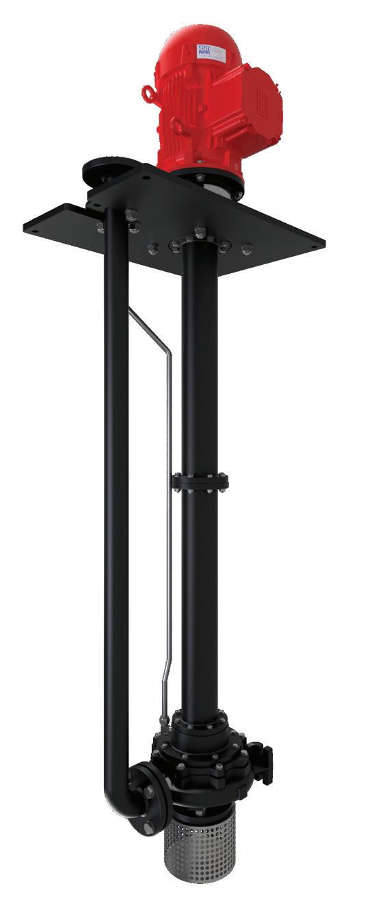
The key to successful, hassle free sump pumping is to eliminate priming issues.
Which is exactly how our ‘V’ Series Vertical shaft column pump works. Unlike a surface mounted unit, the ‘V’ Series is always primed as it’s submerged in the liquid, avoiding the need and expense of a suction line or foot valve and the NPSH restrictions associated with surface mounted pumps.
Its space saving design minimizes or eliminates floor space required for installation with the motor out of the liquid for easy maintenance and monitoring.
With the ability to pump water, suspended solids or semi viscous products and be used in high temperature applications and explosive atmospheres, the ‘V’ Series is also very versatile.
Save time, money and space up top, with an ASM ‘V’ Series pump down below. For more information contact ASM Pumps on (03) 9793 7577 or visit asmpumps.com.au
KEEPING UP IN A CHANGING LANDSCAPE: STATE OF THE INDUSTRY 2019
The sixth annual Pump Industry State of the Industry survey, which was conducted recently, is showing there’s an increasingly positive outlook for the year ahead despite the challenges a changing landscape is presenting. The industry is on the lookout for new opportunities to drive business growth in an increasingly competitive industry. Optimism is high entering 2019, as it rides the success of 2018.
With the few tough years experienced by the industry now appearing to be well and truly over, the industry has steadily been fnding its way back on its feet. That is not to say that there are no challenges facing the industry now or in the future, but there is a willingness by companies to adapt and take hold of the opportunities that are there.
The Pump Industry survey this year produced some interesting insights around what has had a positive and negative impact on the industry, as well as business behaviour. While a number of respondents had a particularly good year in 2018, others struggled depending on the services ofered and sectors they focus on.
Looking back at 2018 and the outlook for
the year ahead
Following a tough few years at the start of the decade, the survey this year shows there is an increasing trend of optimism in 2019, with almost 80 per cent of respondents reporting that they had a positive outlook for their company, and 15 per cent are neutral. There is a slight increase in negative outlook with fve per cent of respondents reporting this for 2019 compared to zero per cent in 2018. The increase in negative
outlook could be attributed to a variety of factors, including the drought and changing customer behaviour. However, overall, comparing results over the past four years shows a growing positive outlook in the industry and a decreasing negative outlook. These results can be seen in Figure 1.
The trend of a positive outlook is also refected in Figure 2, which shows that 21.3 per cent of respondents felt their company’s performance exceeded expectations in 2018 and 55 per cent
said it met expectations. While almost 24 per cent reported that it fell short of expectations, this is almost six per cent lower than what was reported for 2017. Respondents expect this positive growth to continue, with a massive 80 per cent expecting their company to perform better in 2019 than in 2018.
This continued positivity could be due to companies feeling there is a greater stability in the market than in past years, when there was greater uncertainty due to the mining downturn.
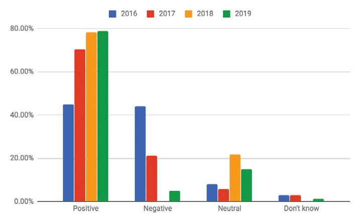
Figure 1: Company confidence has been slowly increasing since the downturn earlier in the decade.
32 pump industry | Summer 2019 | Issue 26 www.pumpindustry.com.au
STATE OF THE INDUSTRY
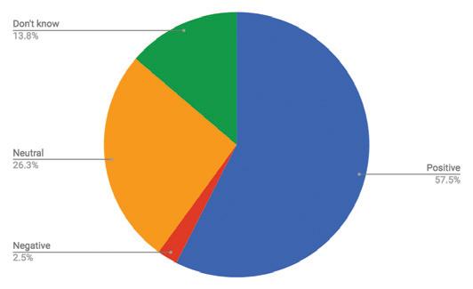
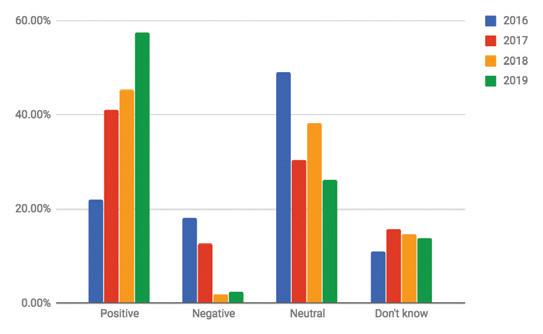
Along with respondents expecting 2019 to be a good year for their company, the industry outlook as a whole is extremely positive — as can be seen in Figure 3. More than 57 per cent of respondents have a positive outlook for the pump industry in 2019, up by more than ten per cent when comparing to the expectations for 2018. This is a massive change since our 2015 survey, which saw only 22 per cent of respondents as having a positive outlook for the following year (Figure 4).

At Brown Brothers Engineers we have expanded our capabilities with two more quality pump manufacturers. In addition to the current world leading brands we can now offer the following range:
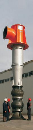
VERTICAL TURBINE PUMPS

Layne Bowler vertical turbine pumps have a proven record under the most demanding and toughest of conditions.
WELCOME TO THE BIG END OF TOWN.
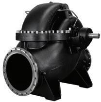
When high head and high flows are required look no further than this quality Italian made range.
• Flows to 5000m3/h
• Head to 220m
• Pumps that exceed EN733 (DIN 24255 standard)
Brown Brothers Engineers have innovative solutions whatever your application. Contact us today about your requirements.
Ph: 1300 4 BBENG www.brownbros.com.au
33 www.pumpindustry.com.au pump industry | Summer 2019 | Issue 26 STATE OF THE INDUSTRY
NCBK Series SKD Series NCA Series
DELIVERING PUMPING SOLUTIONS
03/18
Figure 2: Overall, companies felt that their performance in 2018 met or exceeded expectations.
Figure 3: What is the outlook for the Australian pump industry in 2019?
Figure 4: There has been a trend of increasing optimism in the industry over the past four years.
Performance by vertical
Key to understanding the current state of the pump industry is to examine which particular verticals performed the best and worst for businesses during 2018, and to identify how key sectors are expected to fare in 2019.
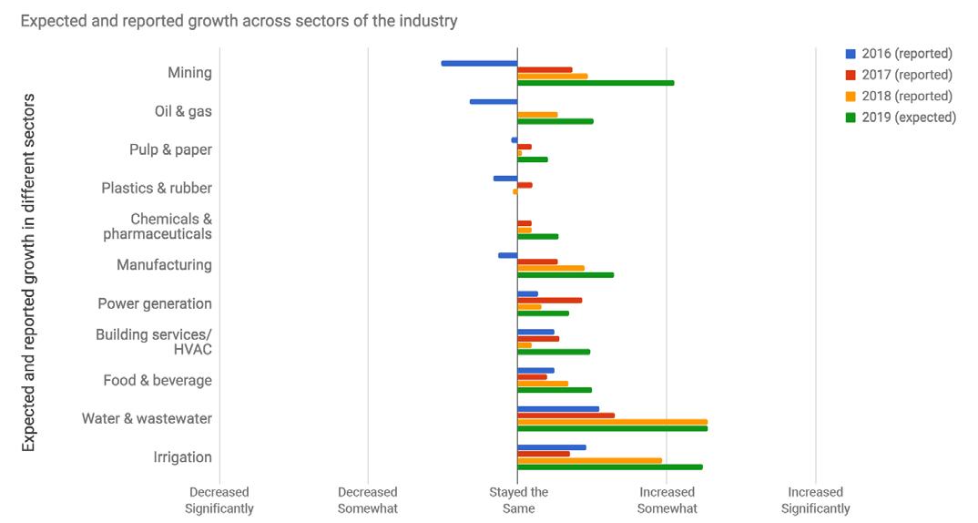
We asked our respondents how the volume of work across key verticals had changed for their businesses during 2018, and how they expected them to change in 2019.
Figure 5 illustrates the actual reported performance of various verticals for our respondents from 2016–2018, and their anticipated performance in 2019.
How did the verticals perform in 2018?
According to our respondents, the best performing verticals were water and wastewater, irrigation, and mining. On the other hand, the vertical that performed the worst was plastics and rubber, which was the only vertical to experience somewhat of a decrease in the volume of work.
There were mixed results in the volume of work reported for 2018 compared to 2017, with building services/ HVAC, power generation, and pulp and paper not performing as well in 2018 as initially expected. Other verticals saw an increase, and in a turnaround, the oil and gas sector saw an increase in work, following a largely negative performance in 2016, and poorer performance in 2017 and 2018 than expected.
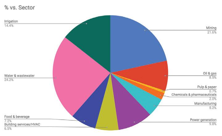
Looking ahead to 2019
Figure 6 shows a breakdown of which verticals are expected to drive growth in 2019. Similar to respondent expectations for 2018, the water and wastewater, and mining industries are expected to be the best performing verticals in 2019. Most respondents think the volume of work in these areas will increase in 2019. The irrigation sector is also expected to see continued growth in 2019, following a greater increase in work in 2018 than originally expected. The outlook for
manufacturing is also positive, with the sector seeing a steady increase in performance over the past few years.
What is making an impact on the industry?
Increasing investment in water and wastewater
Figure 7 shows the areas of growth reported and predicted across the industry. Water and wastewater did slightly better than expected in 2018 with more than 15 per cent of respondents reporting the volume of work had
34 pump industry | Summer 2019 | Issue 26 www.pumpindustry.com.au STATE OF THE INDUSTRY
Figure 5. Reported growth areas by vertical from 2016–2018, and their anticipated performance in 2019.
Figure 6. What are the key verticals expected to drive growth in 2019?
increased signifcantly and more than 40 per cent said it had increased somewhat. Almost a quarter of respondents said the volume of work had not changed, and only 5.66 per cent said there was somewhat of a decrease. This is compared to the reported expectations, where almost 40 per cent thought the volume of work would not change, 28.2 per cent predicted it would increase somewhat and 15.38 per cent said it would increase signifcantly. Expectations for growth in 2019 are in line with the volume of work reported in 2018.
The better than expected results could be attributed to a number of factors, including wariness of performance heading into 2018 following lower-than-predicted growth in 2017. Respondents also noted that a focus and greater spending by government and water authorities on water and wastewater projects helped drive growth.
Factors driving irrigation
Irrigation also saw a much better result in 2018 than originally expected, with 5.13 per cent of respondents initially predicting that the volume of work would increase signifcantly, 23 per
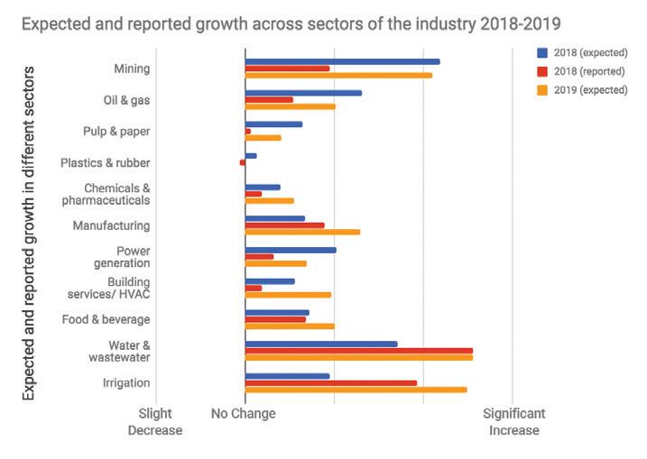
7. Expected and reported growth in different sectors 2018–2019.
cent that it would increase somewhat and another 23 per cent predicted that it wouldn’t change. The reported results were much more positive, with almost 17 per cent saying there was a signifcant increase in work, almost 19 per cent that it increased somewhat and 28.3 per
cent that it didn't change. There was, however, 3.77 per cent that reported the volume of work had decreased somewhat. The better-than-expected growth in the sector has led to a positive prediction for 2019, with the volume of business expected to grow.

Removes up to 90 % of water
● Dewatering of waste & process sludges
● Cost-efficient processing and transportation in one closed unit
● For cold climates the unit can be isolated and heated
Roll-of unit includes:
● Container & geotextile filter bag
● High performance slurry pump*
● Chemical dosing pumps*
● Flocculation reactor module*
● Integrated controls*
*optional
Flowrox GeoBagTM is for:
● Sewage sludge dewatering
● Tailings dewatering
● Concentration of oily sludge
● Separation of precipitated solids and impurities
● Filtration & dewatering of clay, sand and other fne particles
IIoT/AI & remote controllability w/ Flowrox MalibuTM smart platform
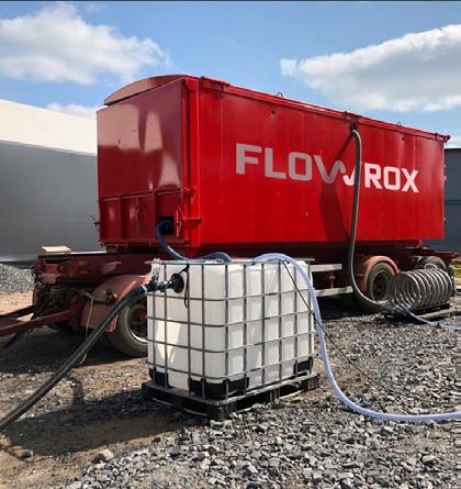
www.fowrox.com
35 www.pumpindustry.com.au pump industry | Summer 2019 | Issue 26 STATE OF THE INDUSTRY Flowrox GeoBagTM — Roll-of geotextile fltration ASK FOR MORE! +61 2 9114 9715 / sales-au@fowrox.com
Figure
There were several factors at play in 2018 that impacted the upturn in the volume of work in the irrigation industry, with respondents citing the requirement for pump servicing and the drought as some of the factors that had an impact. Respondents said favourable conditions would continue into 2019 with a greater demand for irrigation expected. One respondent sees this trend continuing into the near future stating, “Water and wastewater, along with irrigation, are booming markets for at least the next fve years.”
There are upcoming opportunities that the pump industry can jump on, including a record funding commitment by the Federal Government for water infrastructure across regional Australia. Last November, an additional $500 million was promised for the National Water Infrastructure Development Fund. The fund’s expansion to more than $1 billion, as well as the existing $2 billion National Water Infrastructure Loan Facility program, means more than $3 billion is now available from the Federal Government to support state and territory governments and their project partners, to build new water infrastructure, and provide greater social and economic opportunity for Australians.
However, while irrigation has been a booming sector for some, not all respondents saw growth in this sector. Not everyone thought the drought had helped propel business, citing that the continued dry conditions and a lack of water had seen the volume of work in the irrigation sector drop. The outlook considered by these respondents is expected to continue to have a negative impact on their business into 2019 if there isn’t enough rain.
The severe drought across eastern Australia is heavily impacting sentiment in the nation’s agricultural sector, which could negatively impact the pump industry in 2019. The September Rabobank Rural Confdence Survey found the lowest farmer confdence levels recorded since the depths of the millennium drought in 2006. With dry conditions
preventing many farmers from capitalising on what remain high prices for most commodities, the overall Australian rural confdence index dropped signifcantly in the latest quarter, with more than half of those surveyed having a pessimistic view of the 12 months ahead.
The Rabobank survey found 56 per cent of the nation’s farmers now expect conditions in the agricultural economy to deteriorate in the coming 12 months, those expecting an improvement in conditions declined to 13 per cent, while 25 per cent expect similar conditions to 2017.
These sentiments could afect investment in on-farm water infrastructure over the next 12 months, with the report fnding that 21 per cent were intending to decrease investment in their farm businesses, while those looking to maintain current investment levels fell back to 59 per cent, and 18 per cent reported an intention to increase investment. This potential decrease comes despite positive longer-term business outlooks.
It is likely that the pump industry will feel the efects diferently depending on which state they service.
One respondent to our survey noted those around the Murray Darling catchment area in particular could be negatively impacted in the next few years if weather patterns don’t improve, saying, “This will have a signifcant impact on irrigation businesses that don’t have the capability to service pumping infrastructure and are just relying on sales alone for revenue.”
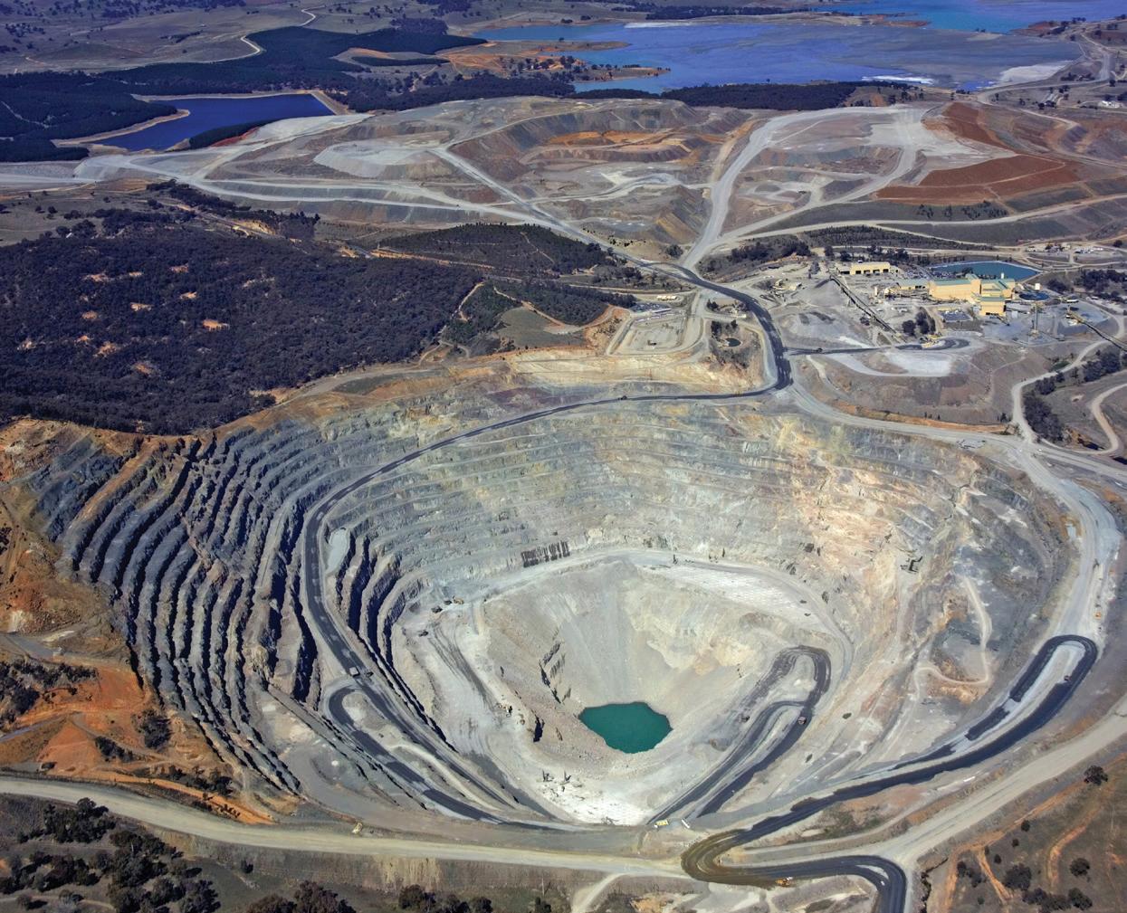
A cautious optimism for mining
In a positive sign for those servicing the mining sector, the mining slump seems to be well and truly over, with a report by the Department of Industry, Innovation and Science in the September edition of Resources and Energy Quarterly predicting a new export boom due to the combination of a weaker Australian dollar and the increasing global demand for coal, oil and LNG.
The overall fndings of the report indicate “strong economic growth, industrial production and manufacturing output” for
36 pump industry | Summer 2019 | Issue 26 www.pumpindustry.com.au STATE OF THE INDUSTRY
While the mining sector is expected to grow in 2019, some respondents remain cautious.
Australia, with resource and energy exports expected to hit a new record high of $252 billion in 2018–19, before falling back to $238 billion in 2019–20.
This outlook was refected in our survey responses with the mining industry seen as one of the key factors that will have a positive efect on the pump industry in 2019 due to an increase in the number of mining projects and companies looking to reduce downtime.
However, not all respondents shared this view, with some seeing the mining industry as having a negative efect, while others remained cautious. One respondent said, “Mining will either remain at the same level or may decrease a little bit, mainly because groundwater tables may get disturbed because of excavation operations.”
We also saw some mixed results in oil and gas, with some optimistic that it will increase, while others predict it will stagnate.
Challenges facing the industry
There were a number of challenges respondents identifed that impacted business in 2018 and would likely impact in 2019.
Government
Government instability and upcoming elections were identifed as one of the challenges impacting the industry. One

ENGINEERS
respondent reported that government instability had increased the level of business and investment pessimism, so companies were more cautious with how and where they were spending money. This sentiment was repeated by another respondent who said their performance for 2018 had been afected due to the underestimation of the impact that politics play in the overall economy.
The outcome of state elections and the federal election next year were also noted as having an impact as it will determine where government funding is spent, with one respondent saying, “If government spending is afected in either direction, this will afect us in some form.” This has already had an impact in 2018 with some respondents reporting that there had been a decrease in government spending due to factors such as conservative end users in local government.
Increased competition
Like last year, increased competition — both internationally and nationally, and online — was reported by respondents as being a key challenge, with a weaker Australian dollar against other currencies, cheap imports and manufacturing costs being some of the reasons cited for emerging competitors and supplier increases.
A reoccurring response to the survey was that customers were still, for the most part, more focused on price over quality in order to get a quicker return on investment. However, other responses suggested some end users are prioritising reduced downtime, reliability and energy efciency over lowest capital cost.
Despite this, companies are not letting increased competition drag down their business, and are fnding ways to make themselves more competitive and set themselves apart from others.
One respondent said, “We have met the high demands of our clients where other companies are falling short on. We have unique motors that other competitors do not have.” Others reported they expect growth from 2019 due to international expansion or will be looking at ways to reduce the impact.
Another respondent noted customers were “looking for price justifcation, lifecycle cost of pump, quality after sales service and on time responses to calls”, which indicates there is an opportunity for companies to highlight the advantages of quality products in the long term, and set themselves apart by providing exceptional customer service.
Enhanced Evaporaton Systems For Efectve Pond Management
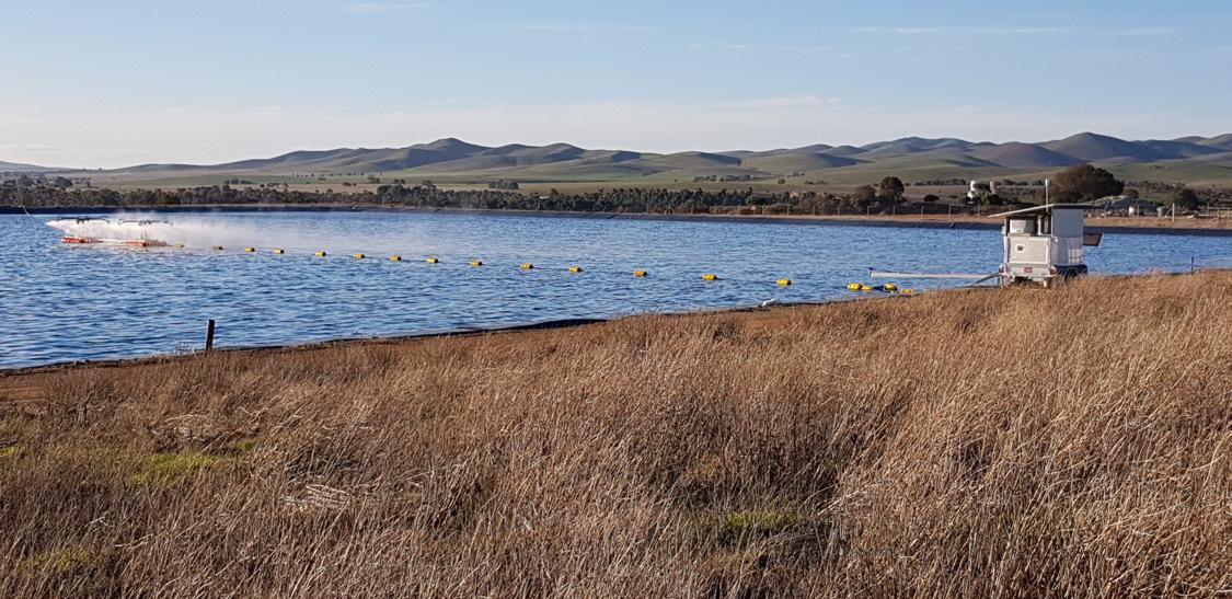
Enquiries: gjc@gjc.com.au 10 Peekarra Street, Regency Park, SA 5010
Phone: 08 8118 6450 www.gjc.com.au

37 www.pumpindustry.com.au pump industry | Summer 2019 | Issue 26 STATE OF THE INDUSTRY
Remote monitoring of weather and system operaton Intelligent adaptve control system to eliminate spray drif No clogging in high TDS waters and suitable for any pH water Quiet Electric
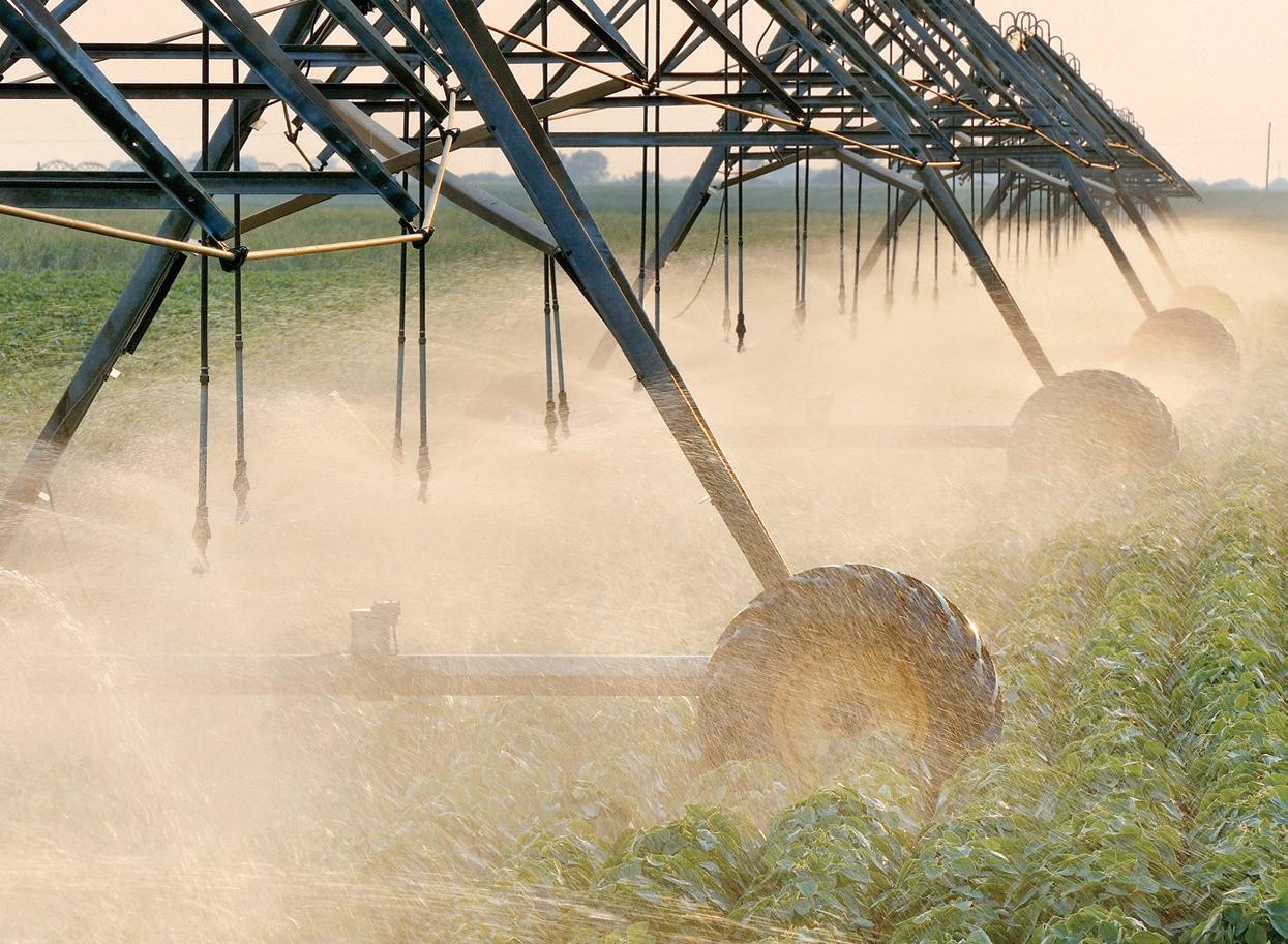
An increase in work in the irrigation sector has led to a positive outlook for 2019.
Training and staf
Another challenge noted by respondents was training and a lack of qualifed professionals. Ensuring people in the industry are kept up to date is vital to meeting standards and having a reliable, long-lasting pump installation. Enticing and keeping trained staf in the industry is also important.
A number of respondents reported that there has been a reduction in qualifed, and interested, tradesman, fnding suitably trained staf, and keeping staf in the industry.
One respondent said there is “reluctance to invest in training of personnel to improve understanding of pump applications”, although another respondent indicated that the demand for qualifed training is increasing.
Employing suitably trained staf or getting staf to undertake regular training through industry association programs and other verifed training courses could impact on businesses moving forward. There is an opportunity for businesses to expand if they are able to design, install and commission a pumping system that is efcient and reduces operating costs, and provide high-quality after sales support, and repair and servicing to ensure best performance of the pumping system. This can only be achieved if staf properly understand the pump and system.
Taking hold of opportunities
While the industry is facing challenges, respondents are fnding new opportunities to diversify operations and move into new markets. There are several areas in particular that companies noted could be taken advantage of to help get them a competitive edge.
Innovation
New technology and innovations such as smart pumps and Internet of Things (IoT) have been slowly gaining traction and are predicted to continue to play a large role in industry expansion in 2019 and beyond.
The extent to which new technology had an impact in 2018 was experienced diferently by respondents, with some reporting little to no impact, moderate impact to mostly positive, but overall there was a sense that it was a growing area of opportunity moving forward and would continue to gain traction, especially in sectors such as building and irrigation where energy efciency is increasingly valued. This was put down to factors such as “more informed and knowledgeable customers wanting technologically advanced material designs”, continuing improvement of technology and the desire for energy savings
One respondent reported, “Electric motor and control technologies have defnitely improved and is going to be an important trend to maintain momentum for those manufacturers to maintain market share. Also the improvements in efciency and NPSHR are very important innovations in large-scale irrigation due to the rising cost and reliability of energy. The pump manufacturers who have focused on these areas are defnitely gaining market share in the irrigation industry.”
Another respondent noted that an increase in the use of variable frequency drive house pumps had propelled business forward in 2018, with 2019 expected to continue this trend and see increased business.
An insight that was provided by one respondent — but has been identifed by others in the industry previously — sees innovation as changing the industry landscape, moving it from a product supply to a system supply system.
While technology and innovation was overall seen as an opportunity for the industry to embrace, there were a few challenges that respondents identifed, including that there will be limited acceptance of these products “until end users understand what to do with the information and what it means to their business”, and the threat of cheap internet sales and imports which could lead to the devaluing of the product due to them being sold at minimal margins.
38 pump industry | Summer 2019 | Issue 26 www.pumpindustry.com.au STATE OF THE INDUSTRY
Energy efciency
As previously mentioned, energy efciency is a key concern for end users who are wanting to reduce operating costs, as well as greenhouse gases. There are currently a number of changes to standards proposed, underway or newly implemented and government grants available for undertaking upgrades, which opens up business opportunities for the replacement of older inefcient units, as well as complete and quality pumping system design.
Standards are seen as also playing a role in this with the new MEI Standards (Minimum Energy Index) identifed as having a big impact due to the target of 25 per cent increase in energy savings.
One respondent said Australian manufacturers are primed to take hold of this opportunity, saying, “We believe we are world leaders here as far as making pumps more efcient goes.”
Respondents noted irrigation as a major sector where energy efciency is providing opportunities.
“This is a driving factor for all of our large-scale irrigators and also irrigation trusts and water authorities. Farming is all about controlling input costs because their products are priced by the commodities and currency markets
of which they have very little control over, so power is becoming a serious drain on their revenue, which is why our customers are upgrading aging low efciency pumping systems and using smarter control philosophies, which is a large opportunity for us,” one respondent said.
Building and HVAC was another sector that was identifed where energy efciency was having an impact.
Renewables
The number of renewable energy projects gaining traction is also having a positive impact on the pump industry, with more than 32 per cent of survey respondents predicting this will continue this year.
Opportunities in pumped hydro, in particular, are increasing as Federal and state governments seek to incorporate more renewables into the power grid. In 2017, an Australian National University report found at least 22,000 suitable locations nationwide for construction of pumped hydro storage plants, which has since been refned to 20 promising sites across diferent states, with a desktop review of geology, highlevel engineering arrangements and approvals requirements.
Funding is the biggest problem currently facing the development of pumped hydro as the high set up costs for private companies is a hindrance to entering the market. There is Federal and state government funding available, but this is primarily for feasibility and pre-development studies, and accelerating engineering, design and development activities.
Solar powered pumps are another area of renewables where respondents said there were increasing opportunities as end users, especially irrigators, seek to reduce the costs of electricity and diesel.
Looking towards the future
With the water and wastewater, mining and irrigation industries expected to continue growing in the new year, and new trends to take advantage of, the Australian pump industry is entering 2019 with an overall positive outlook.
While government and increased competition from online and overseas will bring challenges in 2019, there are also numerous opportunities for the industry in the coming years for those willing and able to take hold of them, and adapt to the changing landscape.
STATE OF THE INDUSTRY
UPGRADING
GENERAL PURPOSE
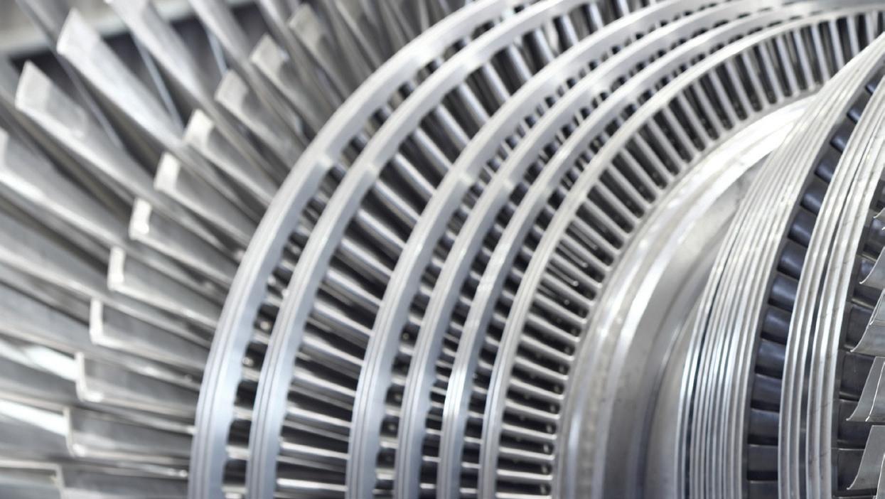 By
By
In a previous issue of Pump Industry, Heinz P. Bloch and Richard Smith looked at costsaving opportunities for general purpose steam turbines. In this issue, they will continue this discussion, examining the advantages of upgrading to new technologies, and the paybacks and expected performance for two upgrade situations.
The
advantage of new technologies
As is shown in the insert on Figure 1, modern replaceable rotating labyrinth devices are readily available that can be installed in existing machines without bearing housing modifcations. Unlike traditional fxed labyrinths, rotating labyrinths use centrifugal force to expel potential contaminants before they reach the oil. During periods of operational idleness, dynamic (axially moving) vapor-blocking O-rings provide a secondary level of protection and, therefore, full compliance with the requirements found in API-611, paragraph 6.10.4.2.11
Lubrication protection must be efective when the equipment is running and also when it is not in operation. With low-cost and traditional labyrinth seals, moisture aspiration occurs while running and also during the shutdown phase. The underlying basics are simple; as the equipment cools, the surrounding ambient air is drawn into the bearing housing.
In order to prevent moisture ingress during this condition, a vapor shut-of device is needed. This shut-of feature is overlooked in many OEM’s (original equipment manufacturers) labyrinth type seals. Figure 1 again helps to explain how a thoroughly well-engineered bearing housing seal prevents moisture ingress when the turbine is operating and also when it is not operating. Temperature resistance is achieved by using graphite foil secondary shaft seals; it should also be noted that several design options are available to fully accommodate the thermal growths encountered in larger multistage general purpose (GP), or even special purpose (SP), steam turbines.
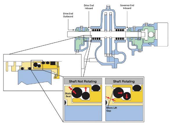
Figure 1. Location and configuration details of a well-proven steam turbine bearing housing protector seal. Note the large cross-section O-ring which seals against a static seat if the shaf is stopped and provides an axial micro-gap with shaf operating.
40 pump industry | Summer 2019 | Issue 26 www.pumpindustry.com.au
OIL & GAS
Heinz P. Bloch, Process Machinery Consulting, and Richard Smith, Oil & Gas Development Director at AESSEAL
1API-611 General Purpose Steam Turbines for Petroleum, Chemical and Gas Industries, May 2008 (5th Edition), American Petroleum Institute, Washington DC
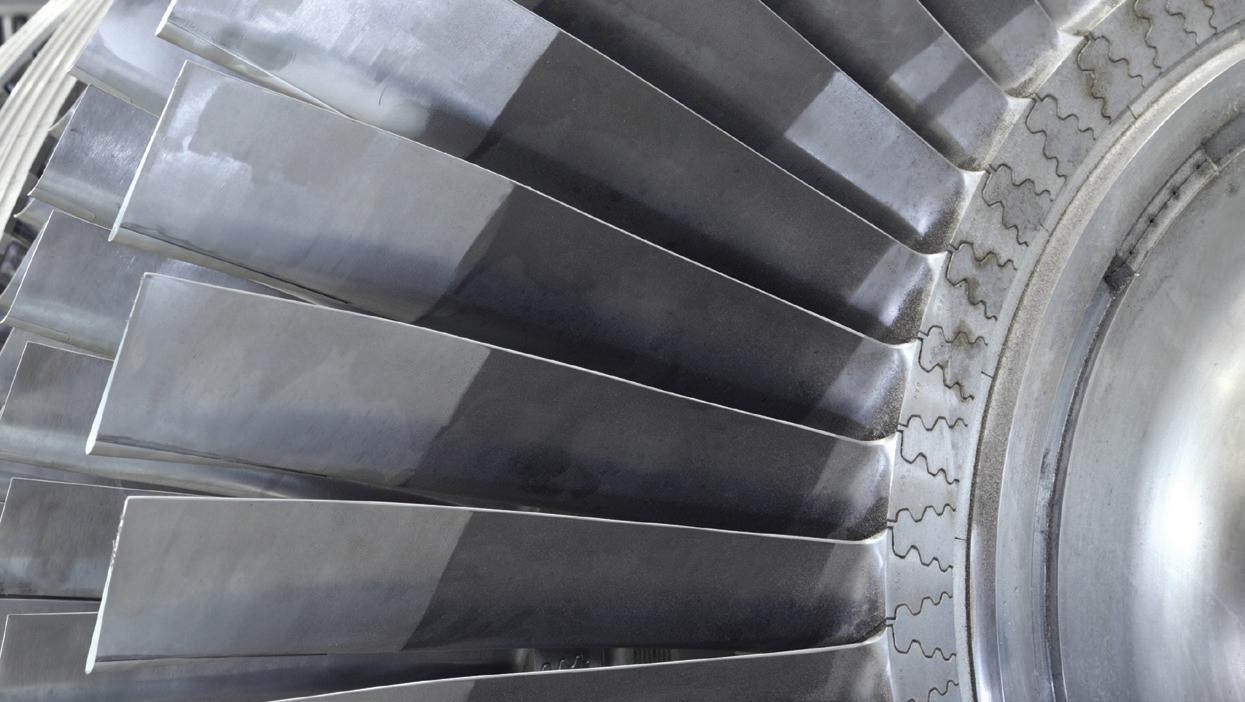
STEAM TURBINES -PART 2
Return on investment for a conversion and upgrading program
The advanced bearing housing protector upgrade should be incorporated into the normal steam turbine maintenance cycle rather than a pre-planned removal cycle. Planned removal would make the upgrade project unnecessarily expensive. It’s again worth mentioning that the approximate total investment required is a relatively negligible $1500 per turbine, and that payback, as indicated later in our sample comparison studies, are often as short as three or four months.
While not universally applicable to every conceivable product make or design, this payback is not unusual for steam turbine bearing housing seals that incorporate the specifc design features shown earlier in Figure 1. In the years leading up to 2017, hundreds of these protector seals have been operating fawlessly in GP steam turbines manufactured by Coppus, Dresser-Rand, Elliott, Terry and Worthington.
Throughout the world, these seals are installed in a wide range of steam turbine sizes. The lube application details in these machines often difer2. Returns-on-investment can difer as well, as comprehensive and detailed payback studies will illustrate. We will therefore distinguish between Situation “a” and Situation “b”.
Situation “a” is a non-pressurised splash lubrication system, also described as a turbine bearing housing with an oil sump. Situation “b” exists if oil is continuously supplied to the bearing housing by a pressurised feed system, generally known as a circulating oil system. This distinction is worthy of emphasis by merely restating that payback periods will difer from as little as three weeks to perhaps 12 months.
The Harms and Rehmann case study3 involved Situation “a” at a world-scale facility in one of the southern United States. In this case study, competent reliability professionals published their actual experience and in-plant statistics. They included a bearing replacement event to the tune of $14,000 and a steam turbine rebuild event costing $35,000; both are meaningful numbers to keep in mind.
Payback for non-pressurised oil splash or sump lubrication systems (Situation “a”)
Here, we are dealing with oil sumps with capacities typically ranging from ½ to 1½ gallons. There is no provision for oil fltration and, to achieve an MTBR of 10 years with only the traditional labyrinth seals, one would probably opt for oil changes every two months. Alternatively, after installing modern bearing housing protector seals (Figure 1), one might reasonably change the oil once per year or perhaps only once every three years.
The vulnerabilities of allowing water and solid contaminants to enter into bearing housings were mentioned earlier. In short, if atmospheric contaminants are allowed to enter and long bearing life is desired nevertheless, the lube oil must be frequently replaced. Cleaning by any of the available on-stream purifcation methods is highly uneconomical on small sump sizes.
We use oils costing from $8.00/gal (straight mineral oil) to $36.00/gal (“synthetic” oil) and assume oil disposal to cost $4.00/gal. The key labour and oil contamination cost contributors that can be eliminated are given on page 42, but the list could probably be expanded.
Performance expectations for sump lubrication systems and “doing nothing”:
Frequent turbine outages and/or repair events are inevitable if unacceptably high oil contamination is invited or tolerated. To do nothing is simply unacceptable and, in a 10year period, would probably require at least three complete rebuilds at $40,000 per occurrence. That’s $120,000, or $12,000 per turbine per year. It follows that a responsible plant can neither allow nor aford to “do nothing”. In essence, we want to do everything that is reasonable and cost-efective to ward of the perils associated with run-to-failure decisions in critical machines.
41 www.pumpindustry.com.au pump industry | Summer 2019 | Issue 26 OIL & GAS
2 Bloch, Heinz P, “Petrochemical Machinery Insights”, (1st Ed, 2016) Elsevier Publishing Company, Oxford, UK and Cambridge, MA, 784 pages, ISBN 978-0-12-809272-9 3 John Harms and Chris Rehmann, “Eliminating Moisture Damage to Bearings on Critical Steam Turbines”, Solutions 2.0 Conference, November 2010
Performance expectations for sump lubrication systems and labyrinth seals:
Pursuing a $400-per-oil-change strategy includes at least three elements: labour, the cost of new oil, and the disposal cost of used oil. Using traditional labyrinth seals is thought to allow owners to opt for six lubricant replacements per year (at $400/event), and to then reasonably expect a 10-year MTBR for the GP steam turbine. With labyrinth seals, there would thus be 60 lubricant replacements between turbine overhauls (occurring every 10 years) and the total outlay would amount to 60 times $400 = $24,000 — $2400/yr.
Performance expectations for sump lubrication systems and advanced bearing housing protector seals:
Upgrading is done with a set of three advanced bearing housing protector seals ($1500 for the set), and thereafter changing the oil only three times in 10 years. This schedule of three oil changes per 10 years is presently being followed by a refnery in the UK after conversion to advanced bearing housing protector seals. In a 10-year period, this refnery expects to pay 3*$400 = $1200 for oil changes. Their 10-year total will amount to $1200+$1500 = $2700. This is equal to $270/yr. One way of calculating the refnery’s payback ratio is $2400/$270 = 9:1.
Payback for pressurised oil feed systems (Situation “b”)
Many background histories have confrmed that as long as steam and other atmospheric contaminants are prevented from entering bearing housings, lube oils can remain serviceable in steam turbines for 10 years and longer. With suitable on-stream purifcation on reservoirs with more than 3000 gallon oil capacity, some US utilities have used the same charge of oil for 25 years. An ethylene plant in Texas used the same charge of mineral oil for 14 years in two large turbomachinery trains. The plant found it convenient to replace the oil, although oil analyses consistently certifed this on-stream purifed oil in the “as new” condition. Of course, our Situation “b“ relates to much smaller pressurised systems without on-stream oil purifcation.
The vulnerabilities of allowing water and contaminants to enter into bearing housings were mentioned earlier. In short, if atmospheric contaminants are allowed to enter and long bearing life is desired nevertheless, then lube oil must either be frequently replaced or the lube oil must be kept clean by onstream purifcation. While entirely feasible, oil changes and/or on-stream purifcation incur the cost of maintenance labour or purifcation equipment or both.
In the absence of spending maintenance money, the ultimate cost of reduced equipment life and/or repair, downtime-related monetary outlays must be considered. Much of this cost can be eliminated with the advanced bearing housing sealing method described here and illustrated in Figure 1. Realistic cost projections are given here, but readers are encouraged to use whatever represents their own local experience for labour and materials. A further distinction must be made if a circulating oil system serves more than one steam turbine, in which case a more detailed analysis would be needed. In other words, our projected expenditures refer to a single steam turbine with its own dedicated circulating system.
Performance expectations for pressurised oil feed systems:
We again assume a 330 gallon oil reservoir (per Figure D-1 in API-611, 5th Edition, 20084) containing oils costing from $8.00/ gal (straight mineral oil) to $36.00 per gallon (3.85 liters) of “synthetic” oil. Oil disposal is assumed to cost $4.00/gal.
With conventional labyrinth seals in a steam turbine equipped with pressurised oil feed system, we could reasonably achieve a 10-year MTBR (mean-time-betweenrepairs), but only if we opted for yearly precautionary oil changes. Extending oil change intervals beyond one year would risk an increase in costly unscheduled downtime events due to unacceptable oil contamination.
We are now contrasting steam turbines with plain labyrinth seals versus steam turbines with the bearing housing protector seals in Figure 1. On a per-year basis, (mineral) oil costs $8/ gal times 330 gal = $2640. Disposal (at $4/gal) will cost $1320. Adding the two items yields $3960 and multiplying by 10 equates to $39,600 over a 10-year period. But now assume spending $1500 for a set of bearing protector seals and thus extending oil replacement to only three in 10 years. This would cost $39,600/3 = $13,200 in 10 years, or $1320 per year. Our set of bearing housing protector seals costs $1500 and will last at least 10 years; the set costs $1500/10 = $150/year. For a simple payback calculation we add $150+$1320 = $1470 and then divide $1470 by $3960 — less than fve months.
A similar calculation pertains to synthetic oils. On a change-each-year-basis (which might be practiced if serious contamination occurs), a charge of synthetic oil costs $36/gal times 330 gal = $11,880. Disposal (at $4/gal) will cost $1320. Adding the two items yields $13,200 and multiplying by 10 equates to $132,000 over a 10-year period. Again, assume spending $1500 for a set of bearing protector seals and planning three oil replacements in 10 years. This would cost $132,000/3 = $44,000 in 10 years, or $4400 per year. Our set of bearing housing protector seals costs $1,500 and, because it will last at least 10 years, the set costs $1500/10 = $150/ year. For a simple payback calculation we look at incremental savings by using a set of bearing housing protector seals: $13,200-$4400 = $ 8800/yr. Our beneft-to-cost ratio is 8800/150 — a rather staggering 58:1.
Even a less optimistic alternative calculation is rather telling; if, for 330 gal of $36/gal synthetic oil, we assume three precautionary oil change and disposal intervals in 10 years, we will have spent $36*330*3/10 or $3564/yr. With a set of bearing protector seals, our initial payback would be 1500/3564 = fve months.
While we have purposely demonstrated diferent ways of calculating returns on investment, the results always confrm that bearing housing protection seals make economic sense.
Comparisons revisited and summarised
Any of several approaches can be used for comparisons and examination of payback. Suppose we view labyrinth seals and make six oil changes per year our basis. In that case, our frst-year outlay (per steam turbine) with labyrinth seals in place would be six times $400 = $2400. We could also say that our frst-year outlay with the upgrade seals shown in Figure 1 equals $400 plus $1500 = $1900. The frst-year payback would be 1900/2400 = <10 months.
pump industry | Summer 2019 | Issue 26 www.pumpindustry.com.au 42 OIL & GAS
4 API-611 General Purpose Steam Turbines for Petroleum, Chemical and Gas Industries, May 2008 (5th Edition), American Petroleum Institute, Washington DC
UNITED PUMPS
SPECIALIST AUSTRALIAN MANUFACTURER OF API 610 PUMPS
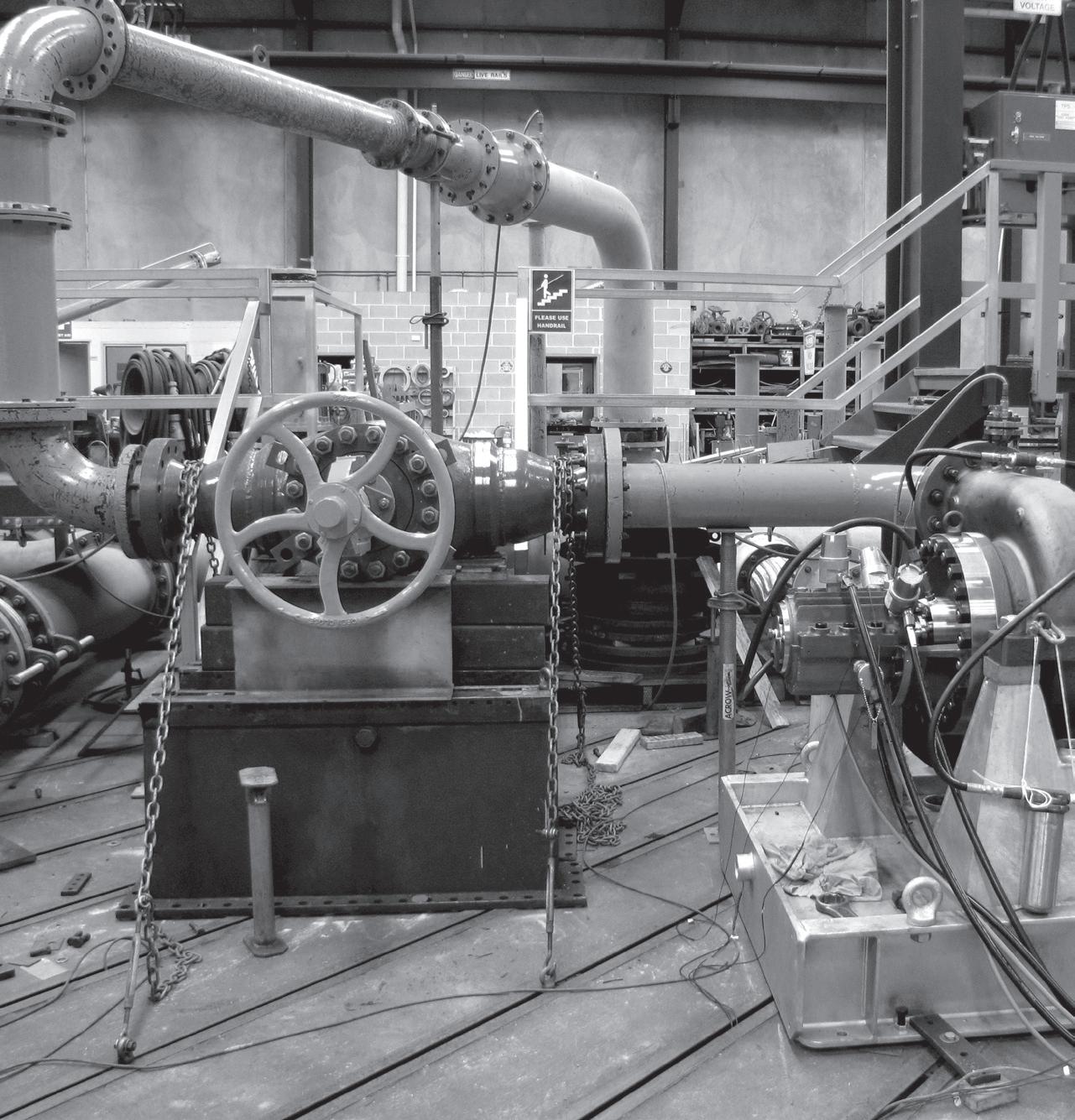
Specialising in custom design, manufacture, repair and service of centrifugal pumps for over 30 years
• Complete range of API 610 (ISO13709)
• Hydraulic and mechanical design
• Custom engineering, retro-fit, redesign
• Performance testing
• Service and repair
43 www.pumpindustry.com.au pump industry | Summer 2019 | Issue 26
www.unitedpumps.com.au T: +61 3 9464 9500 31 Western Avenue, Sunshine Victoria 3020, Australia
Perhaps we would also derive confdence by looking at the incremental savings likely realised by the UK refnery. We know that they installed many sets of modern bearing housing protector seals for $1500/set and, over a three-year period, will have spent $1500 plus $500 for the single oil change, including labour and synthetic oil. They use replacement intervals of three years and their three-year total would be $2000. Staying with labyrinth seals and aiming for the same reliability, this refnery would have to replace a mineral oil six times per year, or 18 times in three years. Their cost would then be 18*$400 = $7200 per GP steam turbine per three years. Calculating in this manner, our payback would be 2000/3 divided by 7200/3. This would result in a payback of somewhere between three and four months. We could also calculate beneft-to-cost-ratios for similarly convincing and equally attractive outcomes.
One last comparison summary again demonstrates the general validity of many diferent cost assessment or cost justifcation or scoping methods. Here, we again start by focusing on the basic labyrinth seal of years ago. We replace oil every two months — six times per year, $400 each time = $2400. However, after retroftting a $1500 set of modern 10-year life bearing housing protector seals (per year cost $1500/10 = $150/year) we would have only a single oil replacement activity per year ($400). As we add $400+$150, we fnd the per-year cost to equal $550. Therefore, our net savings per turbine per year will amount to $2400-$550 = $1850. Upon completion of the project we can multiply this number by 160 to obtain the potential savings for our sample facility which has 160 GP steam turbines. $1850*160 = $296,000.
It’s good to also put a value on reassigning freed-up technical talent to other reliability improvement tasks. Making best use of their time and efort will extend the uptime and proftability of an entire plant. Yearly direct savings approaching $500,000 are obviously within reach once all conversions have been fully implemented.
We have also seen refneries that don’t change oil regularly — some of these send unit operators or “feld persons” into the facility to drain of water. This activity might take 30 minutes and cost $35 per intervention. As we then assume 20 such water drain-of events per year, we arrive at a cost of $700/year. Adding to this an oil change (oil at $8/gal) and a work order which costs $400 to write and process will total roughly $1100 per year. In contrast, the three-year cost of a set of bearing housing protector seals is limited to $1500 and a $400 oil change. The cost will be $1500+$400 = $1900/3 years, or $633/yr. In this instance, we came up with the lowest possible beneft-to-cost-ratio, approximately 2:1. However, we must look at the entire picture and make allowance for the fact that the $1100/yr approach allowed water to enter the bearing housing. Now the cost-to-beneft-ratio will actually be far more favorable than 2:1.
Finally, we chose to be optimistic when we earlier considered fre risk in the previous article. Assume that a plant might expect one turbine-related fre per 2000 repairs or similar interventions — this would give an amortised fre cost of $1500 per event. Suppose we had 160 turbines and an MTBF of 10 years. In that case, the risk is one in 125 years. We would obtain a per-year cost of $3,000,000/125 = $24,000. If we use the “do nothing” approach and an MTBF of only three years for a population of 160 turbines, the risk is one-in-37.5 years and $3,000,000/37.5 = $80,000/yr.
Table 1.
44 pump industry | Summer 2019 | Issue 26 www.pumpindustry.com.au
PHASED 10-YEAR STEAM TURBINE LABTECTA INVESTMENT PROGRAM FOR A REFINERY WITH 160 MACHINES WITH INVESTMENT IN BEARING HOUSING PROTECTION SAVINGS OVER CONVENTIONAL MAINTENANCE EFFORT, Dollars COST COMPARISON “DOING NOTHING” vs. BEARING PROTECTION Col 1 Year Col 2 M/Cs Per YR Col 3 EACH M/C Col 4 All 16, $/YR Col 5 EACH M/C Col 6 All 16, $/YR Col 7 Payback Col 8 Cumulative Savings for 16 M/Cs, $ Col
Repairs/ yr $, EACH Machine Col
Fire Loss $ w / 10 / 3 year MTBF Col 11 Cumulative Fire Avoidance Credit 10 vs. 3 yrs, $ YR 1 16 1500 24,000 1,850 29,600 ~10 mo 29,600 12,000 24k/80k 56,000 YR 2 16 1500 24,000 1,850 29,600 ~10 mo 59,200 12,000 24k/80k 112,000 YR 3 16 1500 24,000 1,850 29,600 ~10 mo 88,800 12,000 24k/80k 168,000 YR 4 16 1500 24,000 1,850 29,600 ~10 mo 118,400 12,000 24k/80k 224,000 YR 5 16 1500 24,000 1,850 29,600 ~10 mo 148,000 12,000 24k/80k 280,000 YR 6 16 1500 24,000 1,850 29,600 ~10 mo 177,600 12,000 24k/80k 336,000 YR 7 16 1500 24,000 1,850 29,600 ~10 mo 207,200 12,000 24k/80k 392,000 YR 8 16 1500 24,000 1,850 29,600 ~10 mo 236,800 12,000 24k/80k 448,000 YR 9 16 1500 24,000 1,850 29,600 ~10 mo 266,400 12,000 24k/80k 504,000 YR 10 16 1500 24,000 1,850 29,600 ~10 mo 296,000 12,000 24k/80k 560,000 TOTAL 160 240,000 296,000 120,000 240k/800k
OIL &
9
10
GAS
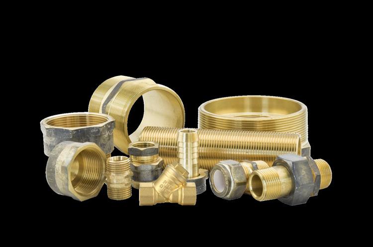
Full range of Watermarked fittings and valves to suit your every requirement

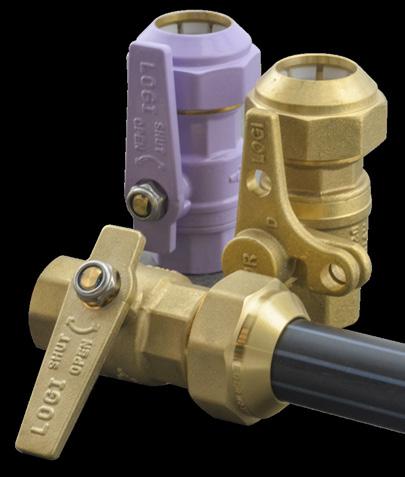
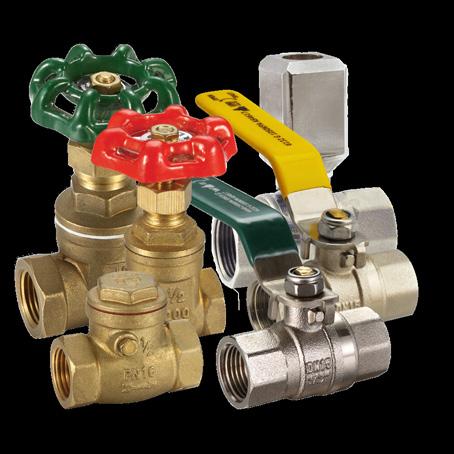
C IVI L
Using a “phased 10-year investment” approach
Of all these and many other possibilities, we decided to elaborate on a phased investment approach and constructed explanatory Table 1. We kept it relatively simple, letting fnancial experts aim for greater precision. But beware; while computer software programs exist that can do the work faster, we adhere to the belief that common sense and experience might be just as valuable as placing seven digits behind the decimal point.
As an aid to visualisation, we constructed Table 1, calling it a “phased 10-year steam turbine upgrade/investment” approach. Our numbers pertain to Situation “a”, where a user has 160 steam turbines, all incorporating small oil sumps. These turbines are aging; they were originally ftted with labyrinth seals. Suppose the client’s or user’s company now wanted to follow through with a phased upgrade/investment approach. In this phased approach we can readily see our yearly outlays and compare these upgrade investments to the resulting savings.
Note that Table 1 is initially divided into the three groupings; Investment, Savings and Cost of Doing Nothing. The groupings are subdivided into a total of 11 columns containing numbers; we will again explain how we arrived at the various numbers. The Investment group is frst; it gives yearly expenditures in three of its four columns:
Column 1 lists 10 consecutive years; each line in this column will refect that we decided to convert 10 per cent of our 160 turbine population-total each year. In other words, we upgrade 16 machines per year.
Column 2 repeats (or merely re-states) that 10 per cent of 160 equals 16 machines; these 16 are involved in the projected conversion/upgrading work in a given year.
Column 3 shows an outlay of $1500 (our “Investment in Greater Reliability”) per set of three bearing housing protector seals installed in each turbine.
Column 4 is obtained by multiplying column 2 times column 3 and the dollars invested per year which, of course, equals $24,000. The 10-year total of $240,000 is shown in the last row of column 4.
Next, there are four columns in the segment labelled “Savings”. We can demonstrate savings by using monthly and cumulative savings attributable to installing advanced bearing housing protector seals versus continuing operation with leakage-allowing conventional labyrinth seals. Recall that our numbers relate to Situation “a” — which is more prevalent worldwide in small GP steam turbines than Situation “b”.
Column 5 shows yearly savings (per steam turbine) after performing the subtraction $2400- $550 = $1850.
Column 6 gives the yearly savings for a total population of 160 machines. We obtain the numbers in column 6 by multiplying the numbers in column 5 by 16 (i.e. $1850*16 = $29,600).
Column 8 lists the cumulative dollar savings for 16 machines; the numbers are obtained by adding a subsequent year’s savings to the sum of all savings realised in preceding years.
Heinz P. Bloch resides in Westminster, Colorado. His professional career commenced in 1962 and included longterm assignments as Exxcon Chemical’s Regional Machinery Specialist for the US. He has authored or co-written close to 700 publications, among them 20 comprehensive books on practical machinery management, failure analysis, failure avoidance, compressors, steam turbines, pumps, oil mist lubrication and practical lubrication for industry. Mr Bloch holds B.S. and M.S. degrees (cum laude) in Mechanical
The last three columns in Table 1 have the heading “doing nothing”. To do nothing implies a run-to-failure (RTF) philosophy. For plants that process fammable, toxic or explosive materials, RTF has been thoroughly discredited. Sadly, run-to-failure philosophies are still occasionally practiced by a few people who will never learn that steam turbine maintenance is far more complex and important than properly maintaining children’s roller skates.
Column 9 is the yearly per machine (M/C = machine) cost of “doing nothing”, i.e. running to failure. Failure would occur after three years of operation, at which time it would cost $36,000 to repair. The per-year portion shown in each row is ⅓ of $36,000 (36k) = $12,000 per machine.
Column 10 was devised to show the cost of steam turbine fres. We expect one fre per 2000 maintenance interventions. For an MTBF of 10 years and 160 steam turbines, 16 repair interventions will be experienced in each of these 10 years. However, with an MTBF of only three years, there would be 53 repairs per year. Yearly fre-related costs would be $24,000 (24k) with an MTBF of 10 years and $80,000 (80k) with an MTBF of merely three years.
Column 11 is obtained by observing, from column 9, the yearly fre losses in the 10-year MTBF and three-year MTBF cases. The losses equal $24,000 and $80,000, respectively. The yearly diference is $56,000. Each year, another $56,000 is added to the previous year’s fgure.
We have reason to believe that Table 1 refects generally accepted investments, savings and costs. Savings exceed investments every year and we fnd the numbers compelling and applicable as reasonable averages.
Overall, we see that the population of general purpose (GP) steam turbines in refneries is aging. In devising Table 1 and electing to use Situation “a”, we took into account that a majority of bearing frames in these GP machines are still ftted with simple stationary labyrinth devices. Experience shows that these components are quite inefective in preventing moisture ingress and contamination of the lube oil. In other words, stationary labyrinth seals represent “old technology” that makes the machines either maintenance-intensive or, with inadequate and deferred maintenance, more failure-prone than deemed acceptable by risk-averse oil refneries.
These and related new technologies are of interest to the risk-averse and are almost always cost-efective in reliability-focused oil refneries. Check into replacing segmented carbon rings in small and medium-size steam turbine glands and consider installing vastly superior STS High Temperature Mechanical Seals. Although frst tested and cost-justifed in 19855, substantially improved versions were recently introduced. These cartridge-mounted High Temperature Mechanical Seals make extensive use of modern dry-running compressor gas seal technology. They should be actively considered as a highly efective means of lowering maintenance costs and extending steam turbine life.
Engineering. He is an ASME Life Fellow and was awarded lifetime registration as a Professional Engineer in New Jersey. Richard Smith served as a Product and Services Manager with international responsibilities for AESSEAL, Inc, located in Rotherham, UK, and Rockford, TN. His 35-year experience is largely concentrated in the development of advanced sealing products for fluid machinery in the petrochemical and petroleum refining industries.
46 pump industry | Summer 2019 | Issue 26 www.pumpindustry.com.au OIL & GAS
“Mechanical Seals for Medium-Pressure Steam Turbines”, presented at the ASLE 40th Annual Meeting in Las Vegas, NV, May 1985 & reprinted in Lubrication Engineering, Nov. 1985
5 Bloch, Heinz P. and Hurl Elliott,


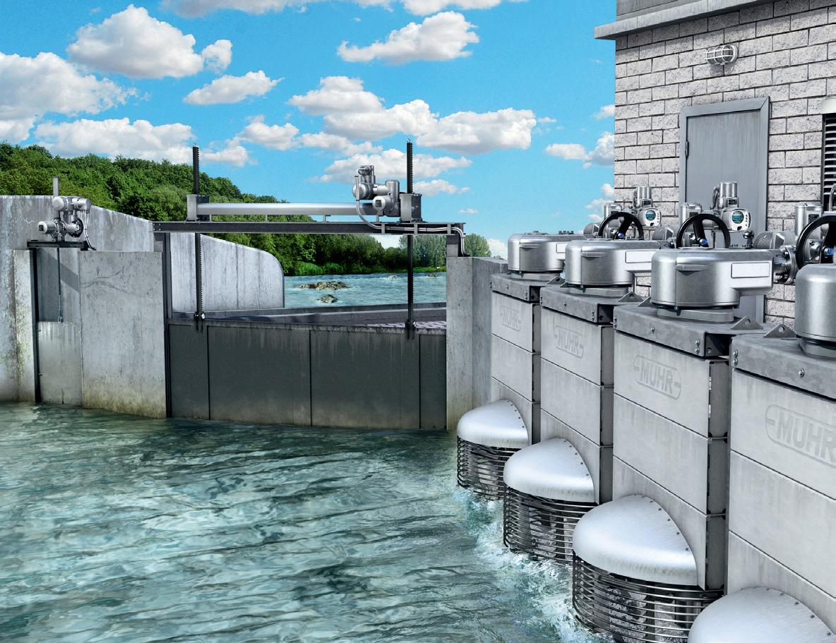

CONSISTENT AUTOMATION
Electric actuators for hydraulic steel structures
Reliable, powerful, robust.
For several decades, AUMA actuators have proved their reliability in automating sluice gates, butterfly valves and gates in weirs, fish ladders, locks, and hydropower plants.
AUMA’s comprehensive portfolio covers torques ranging from 10 Nm to 675,000 Nm offering homogeneous automation schemes throughout the plant: from simple OPEN-CLOSE applications to level control using an integral PID controller.

Learn more ab out AUMA a u tom ation s o lut ions 78 Dickson Avenue Artarmon 02 8437 4300 Info@barron.com.au
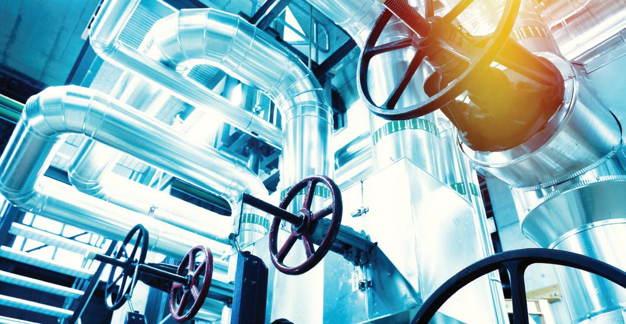
Waterhammer: causes and variables
By Joe Evans, Pump Ed 101
In a previous issue, we used a hypothetical example to illustrate the onset and efects of waterhammer. In this issue, we will investigate its major causes and gain an even better perspective on the variables that contribute to its intensity.
Valve closure and opening
One of the primary causes of waterhammer is the abrupt closure of a valve. Figure 1 shows a main pipeline with a branch circuit that is fed by a “Tee”. At the end of the branch is a valve. The black arrows show the fow direction in the primary and branch lines, and the blue arrow is the length of the branch line.
The valve acts as the primary barrier but this time the secondary barrier, is the “Tee” itself. If water is fowing in the branch line and the valve is closed quickly, a shock wave will develop. Its inception follows the same sequence of events seen in our hypothetical example. One small diference is that some of the intensity of the waves will be lost in the “Tee” as it is open to the main pipeline on either side. Still, a signifcant portion will be refected back towards the valve.
A major diference, in this example, is that we have some control over the valve closure time (in our hypothetical example the valves closed at nearly the speed of light). And, as you will see, closure time has a signifcant efect on the inception and intensity of waterhammer.
In addition, two other variables — fow velocity and pipeline length — are also major factors. The equation P = 0.07 (VL / t) shows the relationship of these three variables and their efect. “P” is the additional pressure generated by the shock wave, “V” is the fow velocity in ft/sec, “L” is the pipe length between the barriers in feet, and “t” is the valve closing time in seconds. 0.07 is the derived constant used to convert the combined variables into pressure. The additional pressure created by the shock wave is directly proportional to fow velocity and pipeline length, and inversely proportional to closure time.
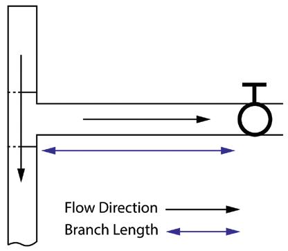
In other words, higher values of V and/or L will increase pressure, while higher values of t will result in a decreased pressure.
The table below shows the results we obtain from this equation when using difering velocities, pipe lengths and closure times. For V the values are fve and ten ft/sec, for L they are 100 and 1000 ft, and for t we will use one and two seconds. In each example we will keep two of the variables constant.
P = 0.07 (5x100) / 1 = 35
P = 0.07 (10x100) / 1 = 70
P = 0.07 (5x1000) / 1 = 350
P = 0.07 (10x1000) / 1 = 700
P = 0.07 (5x100) / 2 = 17.5
P = 0.07 (10x100) / 2 = 35
P = 0.07 (5x1000) / 2 = 175
P = 0.07 (10x1000) / 2 = 350
Both columns of the table illustrate the proportional infuence of velocity and length — pressure increases as they increase. The lower values seen in the right hand column
pump industry | Summer 2019 | Issue 26 www.pumpindustry.com.au 48 VALVES
Figure 1
illustrate the inverse relationship of time — these pressures are half those seen in the left hand column because the closure time has doubled. The value of L is often fxed and depends upon the application, but we can exercise substantial control over the other two variables. By doing so, we can eliminate or greatly reduce the efect of waterhammer.
Pipe diameter and the elasticity of its material also infuence the pressure generated. Larger diameters and more elastic materials absorb some of the intensity of the shock waves, and therefore reduce the pressure generated. Many pipe manufacturers publish curves or tables that show the potential waterhammer pressure increase for various pipe diameters and materials.
Suppose, for a moment, that the branch line valve is closed. If it is opened quickly, we can get an efect similar to that of quick closing. When the valve is opened quickly, the branch line sees an immediate drop in pressure and incoming water from the main line accelerates the previously static column. As friction and other factors restrict its fow, the forward portion of the column can act as the initial barrier and give rise to waterhammer. Usually, its efect is much smaller than that of valve closure and is often referred to as a “surge”. Still, under certain conditions, this surge can be damaging.
In the previous article, I mentioned that the efects of waterhammer can be more signifcant in low pressure systems. The additional pressure generated by a shock wave is proportional to the length of the pipe and velocity of the water fowing in it and is completely independent of its operating pressure. Therefore, the shock wave created in a thousand foot pipe fowing at 5 fps will be the same whether the operating pressure is 50 PSI or 200 PSI. There is a diference though. The ratio of shock pressure to design pressure can be quite a bit higher in the low pressure system — thus the potential for damage can be greater in the lower pressure system.
Pump starts and stops
In many large pumping systems it is normal procedure to start a pump against a closed discharge valve. Once the pump is up to full speed, the valve is opened slowly, fow is initiated, and then increases to its maximum as the valve continues to open. This procedure is reversed when a pump is stopped. Starting and stopping against a valve that is opened or closed will slowly inhibit the initiation of waterhammer. Depending upon the installation, the discharge valve may be operated manually or by some automatic mechanism. One of the shortcomings of manually operated valves occurs during a power outage. When a pump motor loses power, the reduction in pump speed and fow from its discharge occur rapidly. The resulting change of kinetic energy to that of pressure can produce waterhammer waves in the discharge line. Additionally, as the water column reverses direction, the impeller will begin to accelerate backwards. When it reaches its maximum reverse speed, backwards fow is reduced and an additional pressure surge is created.
In most pressure boost applications, a “spring loaded” check
valve is installed at or near the pump discharge and remains closed when the pump is idle. When the pump is started, fow does not begin until the pressure it generates exceeds the pressure on the downstream side of the closed valve. If the downstream pressure is not allowed to decrease below a certain minimum, fow increases slowly and waterhammer inception is avoided or reduced signifcantly. When the pump stops, an unexpected event occurs — a quick closing valve actually inhibits, rather than initiates, waterhammer!
In this particular instance, the spring provides quick closure of the valve and thus prevents the water column from changing direction due to the higher downstream pressure. Even though there is an abrupt change in fow, pressure remains relatively constant throughout the downstream column. If a standard check valve was installed the water column would accelerate backwards, slam the check closed and initiate a shock wave.
Today, VFD control is used in many applications to eliminate the inception of waterhammer during pump starts and stops. This technique, known as soft start and stop, is accomplished by ramping the motor speed up or down over a period of seconds. This allows the fow velocity to increase or decrease much more slowly than it would during across the line starts and stops.
Water column separation and closure
So far our discussion of waterhammer has dealt with something we call single phase systems. In these systems, water remains in a single state (liquid in our examples) regardless of the changes in the hydraulic conditions. The shock waves generated by single phase systems are due to an abrupt change in fow and the resulting transformation of kinetic energy.
The waterhammer generated by water column separation and closure is a two phase process. In a two phase system, water changes state and can exist both as a liquid and a vapor within the same confned volume. This phase change can take place whenever the pressure in a pipeline is reduced to that of the vapor pressure of the water. When a pressure drop occurs, the water column can become separated, in one or more locations, by a pocket of water vapor. When the pressure rises above the vapor pressure the column rejoins or closes and can create a high-pressure wave. Water column separation, by itself, can cause problems in very large diameter or thin wall pipes (they can collapse), but the waterhammer that arises during closure is the more common problem.
Water column separation can occur when a pump is stopped and the water column reverses direction, or in condensate lines where high temperatures can mitigate the need for a large pressure drop. Although both forms can be extremely damaging, condensate lines tend to be far more dangerous. The shock waves generated by column closure can travel in opposite directions and if they hit secondary barriers they can be redirected back towards one another. It would not be unusual for these refected waves to increase in intensity when they collide. This is certainly the case with water and voltage waves, and may account for the often greater damage resulting from closure initiated waterhammer.
www.pumpindustry.com.au pump industry | Summer 2019 | Issue 26 49 VALVES
Joe Evans has been in the pumps industry since 1986 and is passionate about the sharing of knowledge within the industry. To read more of his insights into the world of pumping, visit www.pumped101.com.
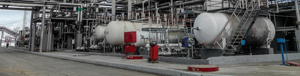
SYSTEM SIMULATION AS A TROUBLESHOOTING TOOL
By Ray Hardee, P. E., Engineered Sofware
Ofen, I am asked why a customer’s system is not operating properly. In many of the cases I have limited operational experience of the customers fluid piping system. By breaking the system down into the pump, process and control elements, one can quickly understand how the piping system operates. Since most of our customers used our piping simulation sofware, they will also include a system simulation file of their system in question.
In this month’s article we will look at a crude oil desalination system, used to remove water and various minerals from the crude oil. The crude oil desalination system is typically the frst process system found in an oil refnery. Figure 1 below provides a piping schematic of the system in question.
This system mixes a small amount of water with the crude to remove contaminants before sending to the fash and separation towers. The crude is preheated and water extracted from the second stage is added, and the mixture is run through a mixing device before entering the frst desalting unit. The frst desalter separates the oil from the brine and sends the brine efuent out for treatment, and sends the cleaned crude stream to the second stage where the process is repeated. The crude from the second stage is sent for further processing.
Once the system is placed in operation, things change, equipment wears, deposits build up, replacements
and modifcations are made. Process or product requirements and raw material properties begin to vary. The initial system design no longer match what the instruments are reporting. This is when the model becomes a great diagnostic tool. The key fact to remember is that if the readings no longer match the validated model, something has changed, and it isn’t the laws of physics upon which the model is based.
When comparing the piping system model to the actual system operation, if the diference between pumps suction and discharge pressures don’t match the model, then further investigation into the pump is warranted. When looking at the customers model the frst question I ask is if the manufacturers supplied pump performance curve was used in building the model. Surprisingly, the answer is usually no. Having correct pump curves is essential to being able to troubleshoot piping systems without signifcant and costly trial and error methods. The pump curve helps
determine if the problem is between the fanges or outside the fanges. A pump not operating on its curve is certainly suspect and should be inspected. If pressure drop across a valve, heat exchanger or other device — or even a specifc length of pipe — doesn’t match the models results, then that can lead you to a root cause. If the pressure drop is too high in the process elements, the fow path may be blocked with debris or build-up. Pressure drop too low? This could lead you to investigate whether there has been erosion, failure in a positioning device or control system error, or even potentially indicate there is a leak somewhere between the sensors. Coupling the comparison of model and actual fow rates with pressure drops is even more revealing. The key point is that consulting the model as a diagnostic tool can help identify root cause more rapidly by pointing us in the right direction.
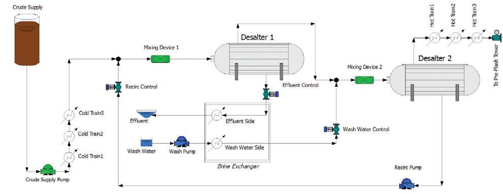
pump industry | Summer 2019 | Issue 26 www.pumpindustry.com.au
50
VALVES Figure 1: Crude desalting system model
Looking at the system
As designed, the three pumps are all running pretty close to their respective best-efciency-points (BEPs), and valves are all within their control ranges. The pumps and the valves are all instrumented, but the individual process devices were not. The water to crude volumetric ratio for each unit was designed to be around 5.2 per cent. Refer to Table 1 for initial system design conditions, with available instrumentation data highlighted in blue. After some time, an operator noted some noise coming from the efuent control valve. The operator checked the other valves and noted that the recirc valve was 100 per cent open and no longer controlling fow, and sampling the mixes going into the desalters showed
the water to crude volumetric ratio going in to Desalter 1 had dropped to 4.8 per cent, and going in to Desalter 2 was now 5.6 per cent.
The operator then took measurements from all the instrumented devices. The readings are shown in Table 2 with design values in brackets for comparison.
Having a system model that provides the expected parameters and pump curves for each pump in the system can be of great beneft in this scenario. One possible cause for the reduced fow in the recirc line would be pump damage or impeller corrosion, which would result in the pump operating of of its curve. Fortunately, we have the pump curve; a quick review of where the pump’s operating point falls shows that it is still
on the curve and operating properly, so we don’t have to shut the system down and take the pump apart to see.
The noise from the efuent control valve indicates there may be cavitation or choked fow in the valve; the asdesigned model indicates choked conditions would be fow over 271 gpm or pressure drop over 76 psi. Since our set point is 270 we are close, but still OK, so the noise is likely due to an increase pressure drop across the valve. Checking the gauge we see the pressure drop across the valve is 82 psi, and the upstream pressure is higher than originally modelled.
Looking at the wash water control valve, we can see it is operating properly, but opens more than the model would expect. We can verify the downstream pressure from that is also higher than originally modelled. The pressure is higher than expected upstream of the Mixing Device 2, but lower downstream of Desalter 2. Now we can zero-in on a probable cause — plugging in Mixing Device 2, which turns out to be the case.
This scenario highlights another way that system analysis is critical not only in the design phase, but in operation and troubleshooting. The two control valves exhibiting the errant behavior were located away from the actual problem. If we took a component view, there may have been more investigation into the valves or even the pump to see what the problem was, but with a validated system model the actual readings from the system can be compared to the expected values in the model, and can be a valuable troubleshooting tool to have in your toolbox, especially in areas or parts of your system where instrumentation is not installed.
When you take ownership for operating your system, make sure you get a copies of the system analyses — including all the pump curves — and keep them up to date. When something goes wrong it will be an invaluable tool for troubleshooting and will be accessible with a touch of a button.
Ray T Hardee, PE, is the Chief Engineer and a principle founder of Engineered Software Inc., creators of PIPEFLO® and PUMP-FLO® software. The PIPE-FLO product line helps some of the largest companies across a variety of industries find hidden profit in the design and operation of their fluid piping systems through simulation software, modeling services, and training opportunities. Hardee is a member of the Hydraulics Institute, ASME Energy Assessment for Pumping Systems standards committee and ISO Pumping System Energy Assessment committee. Ray’s publications include Piping System Fundamentals and contributions to HI’s Pump Life Cycle Cost and Optimizing Piping Systems. He can be reached at SimGuyRay@eng-software.com.
www.pumpindustry.com.au pump industry | Summer 2019 | Issue 26 51 VALVES
Pump Head (ft) Flow (gpm) Eff. (%) Process dP (psi) Crude Supply 354 4770 78% Σ Cold Preheat Train 12.0 Recirculation 102 250 63% Σ Hot Preheat Train 12.9 Wash Water 304 250 65% Mixing Device 1 5.2 Control Pos. (%) Flow (gpm) dP (psi) Mixing Device 2 5.0 Recirc 93% 250 5.2 Brine HX - WW Side 7.8 Effluent 59% 270 76 Brine HX – Effluent Side 9.2 Wash Water 69% 250 22 Desalt Stage 1 15.7 Desalt Stage 2 15.0
Table 1: System elements operating as-designed
Pump Head (ft) Flow (gpm) Eff. (%) Crude Supply 362 [354] 4566 [4770] n/a Recirculation 108 [102] 219 [250] n/a Wash Water 304 [304] 250 [250] n/a Control Pos. (%) Flow (gpm) dP (psi) Recirc 100% [93%] 219 [250] 3.2 [5.2] Effluent 59% [59%] 270 [270] 82 [76] Wash Water 69% [69%] 250 [250] 16 [22]
Table 2: System measurements from instrumented devices [Design values in brackets]
PROCURING ENGINES
FOR THE BARKER INLET POWER STATION
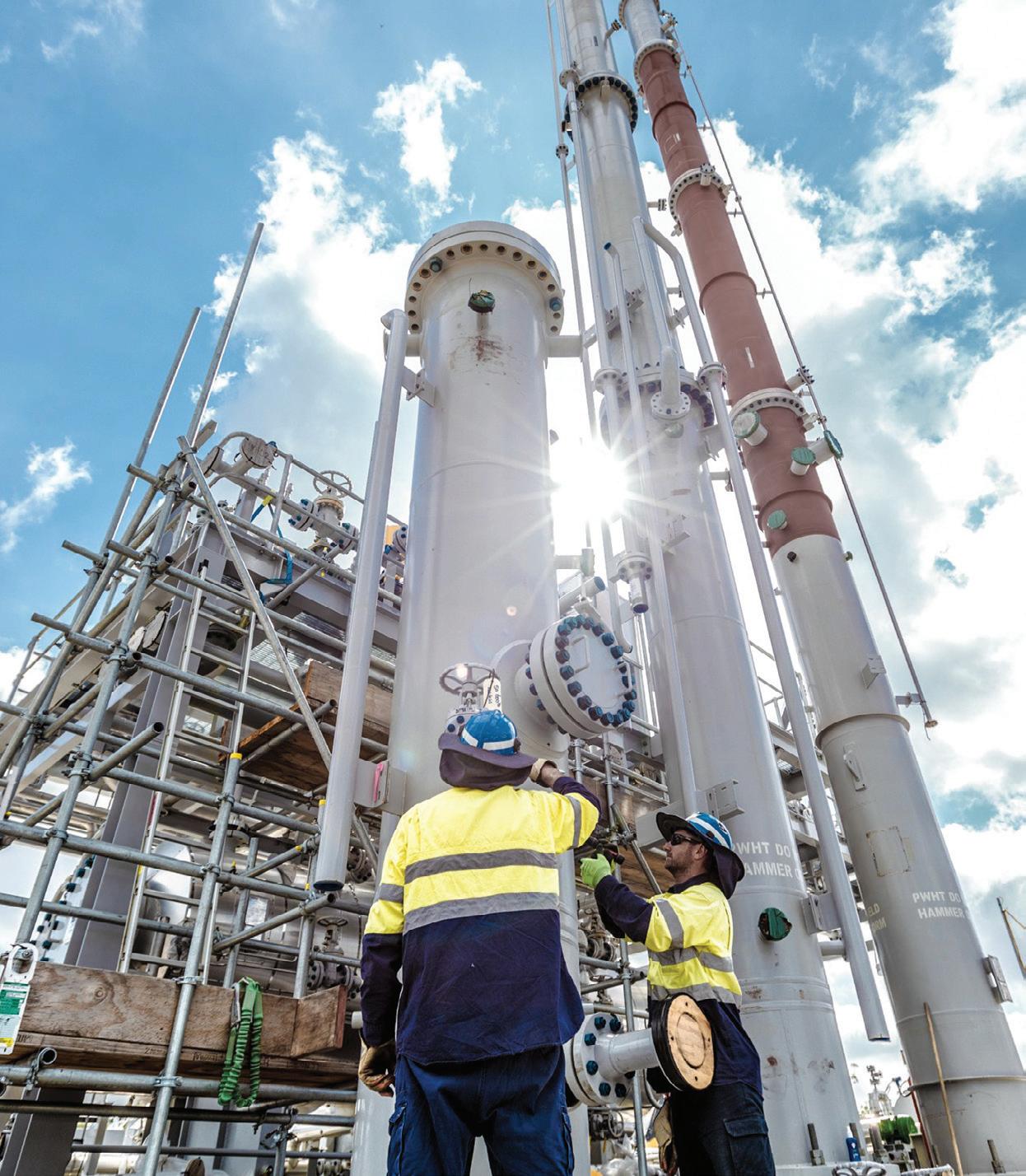
POWER GENERATION pump industry | Summer 2019 | Issue 26 www.pumpindustry.com.au 52

Power generation is changing, with companies like AGL looking to replace aging coal-fired assets with technology that allows them to meet the changing requirements of the market. One such requirement is procuring equipment that will provide fast, flexible and efficient capacity that can respond rapidly to fluctuations that are inherent to renewable generation. We spoke to Dave Johnson, AGL’s General Manager Development and Construction, to learn a bit more about the engines that will power the Barker Inlet Power Station (BIPS), and the process the company goes through when designing and developing new assets.
In July 2017, AGL announced a $295 million investment to develop a 210MW reciprocating engine power station, the Barker Inlet Power Station (BIPS). This station will sit alongside AGL’s Torrens Island Power Station site, 18km from Adelaide’s CBD.
The BIPS will comprise 12 Wartsila 50DF dual-fuel reciprocating engines capable of generating approximately 18MW of output each. The engines operate at high efciency and with a lower heat rate than other forms of fast-start plants currently available. The station will also be capable of operating at full capacity within fve minutes, providing a rapid response to changes in renewable generation supply.
The BIPS will replace two of the four Torrens A turbines, which AGL will progressively mothball from September 2019. AGL also has development approval to build an identical BIPS Stage 2, which would replace the remaining A Station units, although at this stage, no decision has been made to commit to stage 2. This decision may be taken following further assessment of the electricity market in South Australia. The four Torrens B generating units will continue to operate as normal.
As South Australia increases its renewable energy generation, sites like Barker Inlet are an important part of the energy mix. Given the importance of this site to the South Australian market (and indeed the National Electricity Market), we were keen to talk with Dave Johnson about the process the company went through in designing and developing this new asset.
“Torrens A Station turned 50 years old in February 2018, which is quite old for a thermal power station,” said Mr Johnson.
“It has reached the end of its economic life and is being retired in a planned and structured way. The BIPS project will use 12 dual-fuel (natural gas and diesel) low speed reciprocating engine generator sets, each rated at 17.6MW with a total station output of 210MW.”
The engines are manufactured by Wartsila Oy of Finland. Wartsila has been contracted to deliver the entire power station under a turnkey contract based on its established plant design installed across the world.
When it comes to selecting the equipment and suppliers AGL will work with for its large-scale projects, the assessment process is naturally quite complex.
53 pump industry | Summer 2019 | Issue 26
POWER GENERATION
“During the assessment process, we considered a range of aeroderivative gas turbine and reciprocating engine generating plant confgurations,” said Mr Johnson.
“After assessing a wide range of factors, reciprocating engines were deemed to be the best outcome for the BIPS project for the South Australian electricity market.”
Some of the features that led the team to opt for reciprocating engines included:
• Very fexible operation
• Fast start to station full load
• High turndown ratio
• Capable of frequent starts without additional maintenance costs
• High efciency (signifcantly better than gas turbines)
• Lower fuel costs and carbon dioxide emissions
• Lower total project capital cost
Designing and constructing the plant
The construction contract between AGL and Wartsila allows AGL’s BIPS project team to work very closely with Wartsila to review the power station detail design and to monitor the construction and testing of the plant. AGL negotiated a comprehensive set of technical specifcations based on Wartsila’s proven power station design.
According to Mr Johnson, the BIPS project is based on a Wartsila standard plant confguration that has been installed in many parts of the world, particularly into relatively weak networks and large mine site applications. More recently, Wartsila has been selling the same power plants into applications to support wind farm output and for network support, taking advantage of their very fexible and fast response capability. These applications are comparable to the power network in South Australia.

54 pump industry | Summer 2019 | Issue 26 www.pumpindustry.com.au POWER GENERATION
Working with AGL
As part of a large operator in the national energy market, Mr Johnson has plenty of useful advice for service and equipment providers looking to work with business such as AGL.
“It’s important to look to align your values associated with project delivery with those of AGL, and understand the key market drivers associated with the particular project,” said Mr Johnson.
He also advises that companies should expect that AGL will take an active role overseeing the project delivery to ensure a high-quality outcome.
“AGL will expect to work with the contractor during project execution to review and optimise the project outcomes, particularly in the areas of safety and environment,” he added.
“When it comes to power plants specifcally, be clear about the expectations for the operating requirements for the plant, such as peaking or intermediate load, as well as the value of starting fexibility and the real value of efciency over capital cost,” noted Mr Johnson.
Mr Johnson also advised that potential suppliers be aware of the fact that AGL will always be mindful of balancing capital and operating costs.
“Capital and operating costs are assessed in an economic model encompassing the lifetime of the project to determine the project returns against internal hurdle rates,” said Mr Johnson. “The operating profle forecast for the plant is a key input into this analysis which will weight the outcome in favour of capital cost or operating cost.”
Energy efciency is also important to AGL, as it provides both economic and environmental benefts. In the commercial evaluation of a project, efciency is balanced against capital and other costs when considering the overall project life economics.
Building the BIPS
The BIPS is now halfway through the construction process, which is employing 200 people throughout the project.
Ultimately, the BIPS will deliver more reliable, dispatchable power to the National Electricity Market, and it will be 28 per cent more efcient than the Torrens A Station units it is replacing.
“This will deliver gas savings of the same order, reducing costs and lowering emissions,” noted Mr Johnson.
It is expected that the plant will be operational in September 2019.
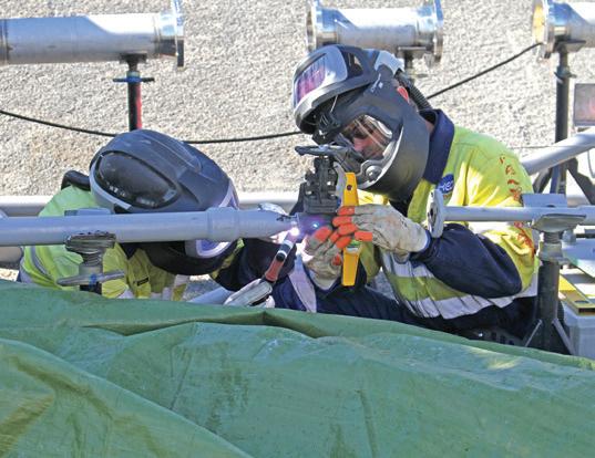

55 www.pumpindustry.com.au pump industry | Summer 2019 | Issue 26 POWER GENERATION

THE PUMPS AND ENGINES POWERING COGENERATION AND TRIGENERATION SYSTEMS
Conventionally, power and heat are supplied from different generation cycles, with electricity being produced in power plants and supplied to customers via the grid, and heat being produced in decentralised boilers and being used on site. However, with rising power prices and a move towards reducing greenhouse gases, alternative electricity generation technologies such as cogeneration and trigeneration have become increasingly popular.
pump industry | Summer 2019 | Issue 26 www.pumpindustry.com.au 56
POWER GENERATION
Using cogeneration and trigeneration technologies to generate electricity and steam from waste heat is well established in many areas, such as industrial applications, which have continuous processing and high steam requirements, commercial applications with large hot water needs, institutional applications, and applications with a steady demand for energy and thermal energy.
What is cogeneration?
Cogeneration — also known as combined heat and power (CHP) — is the simultaneous production of electricity with the recovery and utilisation of heat. It captures the heat produced by electricity generation that would otherwise not be captured or used, for use in various processes including heating, cooling and dehumidifcation.
There are a wide range of proven technologies that are used for cogeneration that can be divided into small-scale applications starting from 1kWel engines for thermal energy supply, up to large-scale power plants to produce electricity.
These can be further divided up into the type of system: topping cycle or bottoming cycle. In a topping cycle system, input energy (fuel) is used to
generate electricity or mechanical energy, with the waste heat generated then captured to provide thermal energy. These systems are most commonly used for on-site processes and are also known as a combined cycle arrangement. Some examples of equipment used in topping cycles include turbine generators, steam turbine generators and reciprocating internal combustion engine generators with heat exchangers.
Topping systems consist of four basic components:
• Prime mover — such as turbines (combustion, steam and micro) — which is the frst stage of the system, and drives the electrical generator and produces by-product
• Electric generator, such as synchronous, inverters and induction
• Heat exchanger (heat recovery system)
• Control system (control and operating system)
Bottoming cycle systems are most commonly used in heavy industry. These systems work in reverse to topping cycles, producing heat from fuel combustion or a heat generating chemical reaction with electricity generated from the exhaust heat by a waste heat recovery boiler and steam turbine. This is generally through steam or organic Rankine cycle (ORC).
BRAINLESS PUMPS
Let’s talk about trigeneration
Trigeneration is an extension of cogeneration, producing not only electricity and heating, but cooling as well. Along with the four basic components of a cogeneration system listed above, it also includes an absorption cooling unit (or other thermally-powered refrigeration devices) that produce cooling by converting waste heat into chilled water.
How are pumps used in these systems?
As well as the use of engines, pumps are used throughout the cogeneration and trigeneration process to push waste heat through the system and to send the energy to the rest of the site as cooled or hot water. The most common pumps used for these processes are feedwater, circulating, condensate, process and heat pumps, which are used for the following tasks:
• To reject heat from the generator and absorption chiller for both utilised and rejected heat streams
• To circulate/transport waste heat or absorption chiller output from the plant to the primary or third party clients
On-board controls and variable speed drives (VSDs) are also found on equipment around the plant.
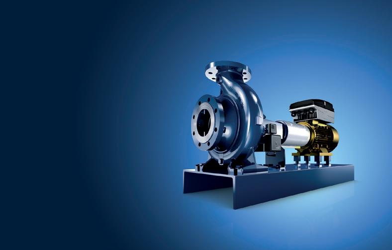
57 www.pumpindustry.com.au pump industry | Summer 2019 | Issue 26
Our technology. Your success. Pumps n Valves n Service Make your life easier by relying on smart solutions for your systems. KSB offers you innovative digital products and services that will make your systems more adaptable and effcient. Learn more. www.ksb.com.au
SOON BE POINTLESS. AD_200x134_EtanormSuprem_en_180906.indd 1 06.09.18 09:27 POWER GENERATION
WILL
POWER GENERATION
Sizing and selecting the prime mover
Sizing equipment for cogeneration and trigeneration systems is vital for the system to be successful. Depending on the project, in some cases it will be better to select the equipment before sizing, while in others it will make more sense to size frst.
The main factors that will determine equipment and size selection are:
• The fuel(s) available or the temperature of waste heat available if it is a waste heat recovery system
• Temperature of heat required at the site
• Heat to power ratio
• Required electrical output
• Form of thermal load and conditions
Other secondary factors that need to be considered include available space, air emissions, noise, engine turndown, and maintenance and reliability.
There are a variety of prime movers that can be used, but the three most common types are reciprocating engines, gas turbines and steam turbines.
Reciprocating engines
Reciprocating engines are commonly used in cogeneration and trigeneration systems due to their high electrical efciency and good part load efciency, which makes them a low-cost reliable option. Their exhaust heat characteristics also make them ideal for producing hot water. Other advantages include fast start-up and low pressure gas fuel.
They typically provide energy
efciency between 25-40 per cent, with efciency increasing in size, with units ranging between 50-4000kW. They are usually used along with heat exchangers to recover heat from waste heat sources such as engine cooling circuit, engine exhaust, oil and intercooler.
However, compared to other prime movers, reciprocating engines have a high relative maintenance cost per MWh, relatively high emissions, and low grade heat from engine cooling. They also have to be cooled if the heat is not used.
Reciprocating engines are best suited for non-industrial, smaller sites, that have a higher demand for hot water.
Gas turbines
Gas turbines — including microturbines — use a steady stream of burning fuel to drive the turbine to generate power, with the heat recovered from the exhaust gases recovered for space or process heating. They have a higher reliability than reciprocating engines, making them ideal for applications where backup power is very important. They also have low emissions, high exhaust heat grade and minimal cooling is required.
Gas turbines typically provide electrical efciency ranges from around 21 per cent for microturbines, 25 per cent for small turbines, and up to 36 per cent for large turbines, with sizes ranging from 30-250kW for microturbines and 50-4000kW for other sizes.
Compared to other prime movers, gas turbines have several disadvantages including medium pressure gas fuel, poor
part load efciency, output falls with increases in ambient temperatures, and their performance degrades over time.
Larger turbines are most commonly used for large-scale systems, while microturbines can be found in smallscale commercial systems.
Steam turbines
Steam turbines use high-pressure steam generated in a boiler to drive the turbine, with maximum electrical efciency realised when the steam is condensed and pumped back to the boiler as hot water. They have a high reliability as well as thermal efciency, and are compact, have versatile confguration and run on heat instead of fuel.
They have an efciency range between 77.6–82.5 per cent with the size of the turbine and the pressure at which the steam is extracted determining electrical efciency. They range in size from 30-10,000kW.
Some disadvantages of steam turbines include their higher cost at smaller sizes, a high grade heat required, and low electrical conversion.
Steam turbines are typically suited for large-scale applications or applications where the amount of heat required is greater than the amount of power.
With the economical and environmental benefts being a key motivator towards building cogeneration and trigeneration systems, selecting the right pumps and engines at the most appropriate size for the individual system is imperative to achieve the best possible efciencies.
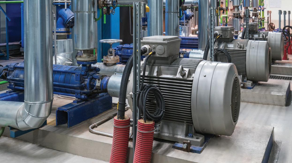
58 pump industry | Summer 2019 | Issue 26 www.pumpindustry.com.au
Pumps in a cogeneration plant.
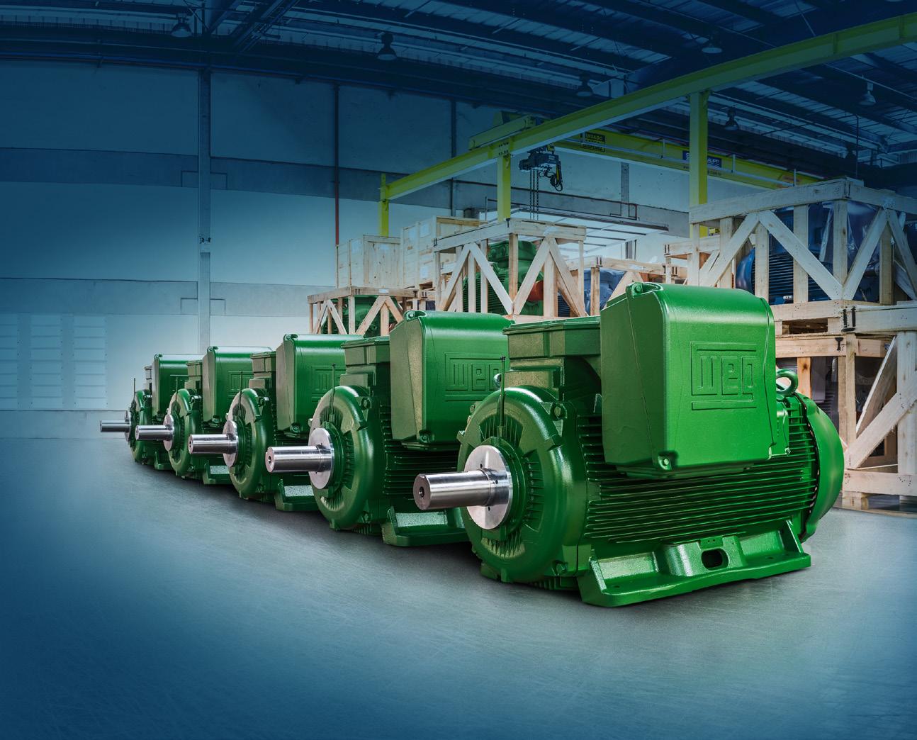
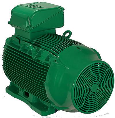

www.weg.net
W22 E3 MOTORS ARE ESSENTIAL WHEN IT COMES TO ENERGY SAVINGS With superior efficiency levels, the W22 E3 reduces energy consumption, offers excellent cost effectiveness, and consequently greater productivity and lower costs. Motors | Automation | Energy | Transmission & Distribution | Coatings
transforming energy into solutions
FIRE Batery failures can mean pump sets fail to perform in a fire, puting the entire fire protection system and therefore lives in jeopardy.
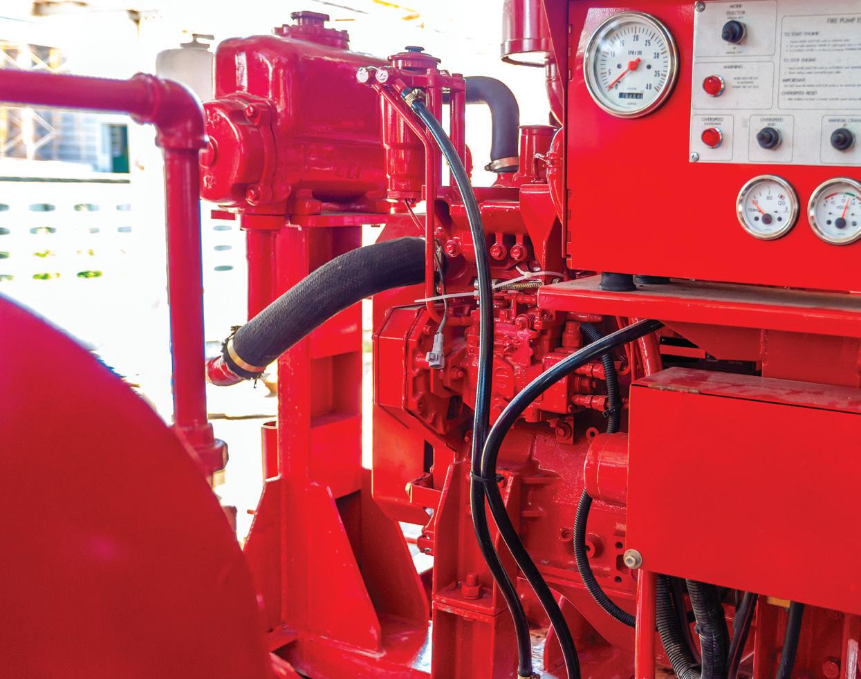
BATTERY FAILURE RISKS IN FIRE PUMPS
By Tom Bicknell, Fire Protection Association Australia
Pump sets are a critical part of fire hydrant and fire sprinklers systems. It is important to be aware of one of the key risks to this important equipment — batery failure. Through reports from its members, peak industry body Fire Protection Association Australia (FPA Australia) is aware of common faults with bateries supporting pump sets associated with fire protection systems.
The problem
The consistent fault reported has been that fooded-cell lead-acid batteries are ‘exploding’. This is thought to be a result of failure and rupture of the battery casing due to internal gas accumulation, and in some cases ignition of this gas.
Reported failures or ruptures are likely to be the result of incorrect charging of fooded-cell lead-acid automotive batteries that have been poorly maintained. Incorrect charging can cause electrolysis of the electrolyte
fuid (sulphuric acid and water) that surrounds the lead plates within the battery. Electrolysis produces hydrogen and oxygen gases, and depletes the electrolyte of water.
While these types of batteries typically have vent holes to allow gases to escape the casing, these are insufcient to expel a high rate of gas production. Gas build-up can swell the casing, which may lead to ruptures and leakage of the fuid. Any spark associated with this build-up of gas will result in an explosion.
In the frst instance, failure or rupture of the battery casing due to internal gas accumulation is a signifcant occupational health and safety issue. The corrosive substances contained within the battery casing are particularly harmful to clothing, skin and eyes and can be fatal if ingested. This is particularly concerning as typically there is no prior warning that failure or rupture is imminent when gases are ignited.
Such failures may also render the diesel fre pump set inoperable, which may also afect the performance of the fre hydrant or fre sprinkler system it serves.
pump industry | Summer 2019 | Issue 26 www.pumpindustry.com.au 60
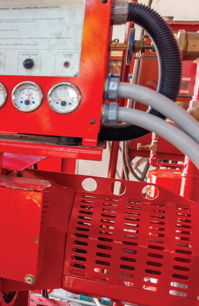
The right battery
The prescriptive deemed-to-satisfy provisions of the Building Code of Australia, as referenced by federal, state and territory governments across Australia, require fre hydrant and sprinkler systems to be installed in accordance with the following standards:
• AS 2419.1-2005, Fire hydrant installations – System design, installation and commissioning
• AS 2118.1-2017, Automatic fre sprinkler systems – General systems
• AS 2118.4-2012, Automatic fre sprinkler systems – Sprinkler protection for accommodation buildings not exceeding four storeys in height
• AS 2118.6-2012, Automatic fre sprinkler systems – Combined sprinkler and hydrant systems in multi-storey buildings
All of these standards require fre compression-ignition (diesel) pump sets associated with these systems to be installed in accordance with AS 2941, Fixed fre protection installations –Pumpset systems, although the edition may vary.
The previous version of this Standard, AS 2941-2008, references a further standard which covered lead-acid batteries, AS 4029. Batteries which were compliant with AS 4029 were recommended as reducing the risk of explosion. Obtaining

SANDPIPER Air Operated Double Diaphragm Pumps
• Capacity: To 59 m³/hr
• Pressure: To 8.6 bar
• Temperature: To 150°C
• Viscosities: To 25,000 cps
Applications
Chemical Processing, Mining, Paints, Food Processing, Industrial Maintenance, Electronics, Construction, Utilities
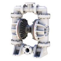
PULSAFEEDER Metering Pumps
• Capacity: To 52m³/hr
• Pressure: To 383 bar
• Temperature: To 260°C
• Viscosities: To 25,000 cps
Applications
Water and Wastewater Treatment, Chemical Processing, Hydrocarbon Processing, Food Processing
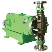
ALBIN Peristaltic / Hose Pumps
• Capacity: To 155m³/hr
• Pressure: To 15 bar
• Temperature: To 50°C
• Viscosities: To 100,000 cps Applications
Mining, Thickener Underfow, Pulp and Paper, Filter Press, Brewery, Water Treatment, Quarry, Grout, Concrete, Waste Liquids
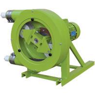
LOWARA Single & Multistage Centrifugal Pumps
• Capacity: To 187m³/hr
• Pressure: To 15 bar
• Temperature: To 150°C
• Viscosities: To 500,000 cps
Applications
Pressure Boosting, Industrial Washing, Water Supply, Water Conditioning, Demineralised Water, Glycol, Boiler Feed, Multi-pump, Pressure Sprinkler Systems
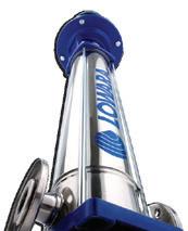
Visit kelairpumps.com.au for more information on our extensive range today.
61 www.pumpindustry.com.au pump industry | Summer 2019 | Issue 26 FIRE CALL 1300 789 466 WHEN PUMP KNOWLEDGE MATTERS When Pump Knowledge Matters KELAIR PUMPS AUSTRALIA 1300 789 466 www.kelairpumps.com.au 06/18 Kelair has the industrial pump for any of your applications.
confrmation from battery manufacturers that their products had this compliance, however, was often difcult.
In the current version of the fre protection pump set standard, AS 29412013, the AS 4029 battery standard is not referenced, and instead focuses on the performance requirements for leadacid batteries used in pump sets. These requirements, if met, will signifcantly reduce the risk of explosion.
FPA Australia also recommends the following steps to choose and maintain the battery correctly:
• The battery is correctly maintained
• The battery is of the absorbed glass matt (AGM) type. These batteries do not require maintenance of the
electrolyte fuid and are sealed except for the inclusion of a safety pressure relief valve to discharge gas build-up. The technology adopted by AGM batteries produces water as a by-product of the chemical reaction process. This means that there is no requirement to maintain electrolyte levels manually. This eliminates the identifed risk of explosion that results from batteries drying out through depletion of electrolyte
• The correct foat charge voltage is used. Float charge voltage is commonly recommended to be between 13.0 VDC and 13.8 VDC at 26.7°C; however, each manufacturer will have a specifc
charge voltage for their batteries. It is extremely important that the foat charge voltage of the battery is set in accordance with the battery manufacturer’s requirements to prevent incorrect charging and gas build-up, which may result in an explosion risk.
The solution
FPA Australia recommends that stakeholders take the following steps to ensure the safety and integrity of batteries supporting fre pump sets:
1. Wear eye protection and appropriate personal protective equipment (PPE) when conducting maintenance
2. Use additional caution at pump set start up (either manual start up or
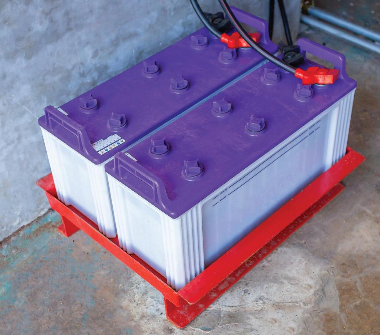
62 pump industry | Summer 2019 | Issue 26 www.pumpindustry.com.au FIRE
FPA Australia recommends the use of sealed absorbed glass mat bateries in fire pumpsets.
when automatic start up is expected after instigating pressure drop of fre protection systems)
3. Observe OH&S rules that prevent the introduction of ignition sources within the proximity of batteries
4. Where possible, determine that installed batteries comply with AS 4029.2 . Where batteries have not been marked, check with the supplier of the batteries to ensure their compliance
5. Batteries should be of the Absorbed Glass Matt (AGM) type, regardless of compliance with AS 4029.2, to reduce the likelihood of failure or explosion due to gas build-up caused by incorrect charging and depletion of electrolyte

6. Always make sure the maintenance and the foat charge voltage of the battery are in accordance with the manufacturer’s requirements
7. Ensure that any documentation associated with installation of fre pump sets clearly specifes the use of batteries in accordance with recommendations 1 to 6 above. In particular, when replacing the battery, replace any fooded-cell lead-acid battery with an AGM type battery. This may require the charging voltage to be readjusted
8. Where wet (fooded-cell) batteries with cell caps are ftted, check the electrolyte levels at each service or test before starting the diesel motor.
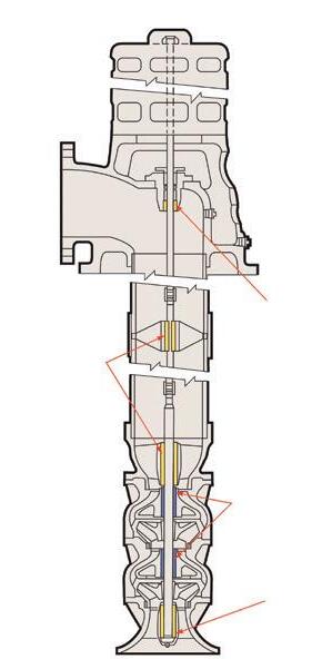
If the electrolyte level is at or below the level of the plates, distilled water must be added before attempting to start the pump. A sufcient quantity of distilled water should be left where batteries are located at each site for battery top up
9. Consider replacing existing batteries if the system’s original installation pre-dates the AS 2941-2008 requirement or if the batteries are older than two years. Mark or record the date the battery was installed using an indelible marker or similar method
10. Install appropriate warning signage
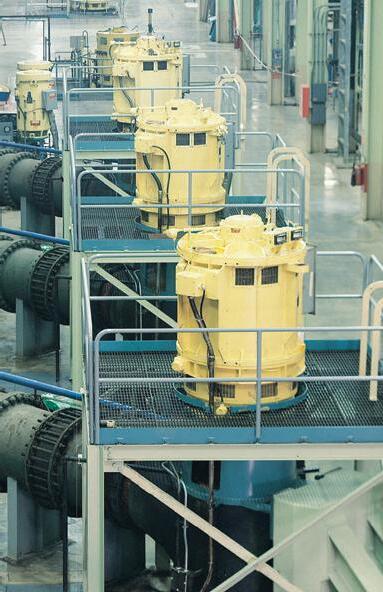
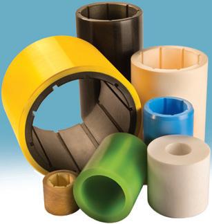


63 www.pumpindustry.com.au pump industry | Summer 2019 | Issue 26 FIRE
ThorPlas-Blue
XL PT80 Composite SXL
ThorPlas-White
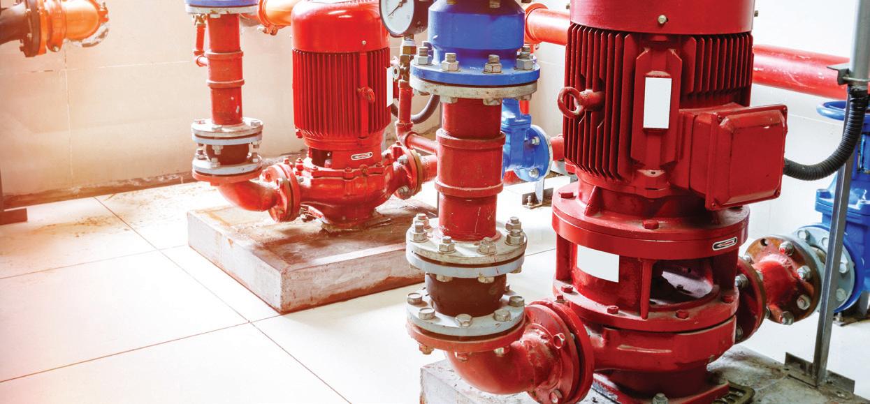
Complying with FIRE PUMP STANDARDS
The Pump Industry Association (PIA) has been working with the Fire Protection Association Australia (FPAA) to create a checklist to ensure close compliance with the requirements listed in AS 2941:2013 Fixed fire protection installations - Pumpset systems. Following discussions, an agreement has been reached on the acceptable format for the checklist.
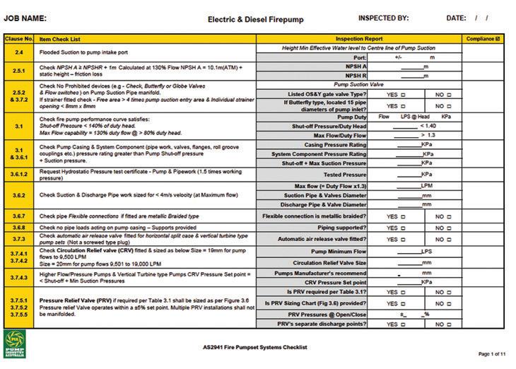
Electric and diesel driven fre pumps are often complex units — which are vital in the protection of life and property in sprinklered buildings — so it is important to verify that every unit complies with the technical requirements of AS 2941 to ensure absolute reliability.
AS 2941:2013 sets out the requirements for pump set systems used in various types of fre protection systems such as sprinkler, hydrant, water spray and hose reel systems. The standard provides designers, manufacturers, installers and testers with minimum requirements for the design, manufacture, installation, commissioning and testing of fre pump sets including acceptance testing of electrical and compression-ignition drives.
To ensure the standard is met, a checklist has now been produced that can be used by all suppliers of fre pump equipment at the key stages of design, manufacture and installation.
The checklist can now be downloaded for free from the PIA website and it is encouraged that everyone use the appropriate sections in their own QA program when designing, manufacturing and commissioning pump sets for sprinkler systems and other fixed fire installations.
64 pump industry | Summer 2019 | Issue 26 www.pumpindustry.com.au
FIRE


The pump industry relies on expertise from a large and varied range of specialists, from experts in particular pump types to those with an intimate understanding of pump reliability; and from researchers who delve into the particulars of pump curves to experts in pump efficiency. To draw upon the wealth of expert knowledge the Australian pump industry has to offer, Pump Industry has established a panel of experts to answer all your pumping questions.
This edition of Ask an Expert will look at valveless flow control with progressive cavity pumps and their usefulness in flow control, and oil & gas applications.
Q: How would switching to valveless fow control in pumps impact my operation?
A: Many think utilising a centrifugal pump and control valve for fow control applications is the only option; however, progressive cavity (PC) pumps are particularly well suited in these areas due to their valveless design and controllable fow. The term for the innovative use of PC pumps in these applications has been coined valveless fow control.
Function
In a PC pump, a single helix rotor turns insides a double helix stator to create cavities which progress from suction to discharge. The compression ft between the rotor and the stator creates seal lines that keep the cavities separate as they move through the pump with each rotation. This compression enables the pump to act like a valve, thereby reducing slip, minimising pulsations and lowering shear rates. PC pumps
also precisely meter and gently convey thin to highly viscous media, with or without solids and in a wide range of temperatures.
Common issues resolved
Common issues with centrifugal and control valve combinations include cavitation, leaks, obstructions, erosion, hysteresis and modulation. Centrifugal pumps can also lose prime between batches or from alternating pumps.
When considering process control, a progressive cavity pump, fow meter and variable frequency drive ofer a simpler and easier solution. The PC
pump self primes and acts not only as the pump but also as a control valve, providing better fow control. They are not afected by changing pressures and hysteresis and modulation can be virtually eliminated. There is also no worrying about internal or external air leaks or obstructions in the suction or discharge pipework.
Applications
Progressive cavity pumps are replacing centrifugal and control valve combinations in applications where fow control is vital such as wastewater treatment and chemical metering. For
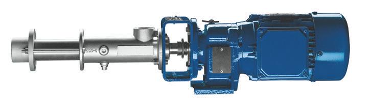
66 pump industry | Summer 2019 | Issue 26 www.pumpindustry.com.au
ASK AN EXPERT
Progressive cavity metering pump.
example, transferring slurry to a blending tank is efciently handled with a valveless PC pump. The pumps ofer increased reliability, reduced maintenance along with decreased capital, operating and energy costs.
Contact SEEPEX to experience the benefts of valveless fow control for yourself.
Q: Do progressive cavity pumps additionally support the wide range of applications in oil and gas from upstream to downstream production?
A: Drilling waste management, produced water treatment, fraccing, LACT, multiphase boosting and crude oil transfer, MEG reclamation, sump/caisson emptying, FPSO and refnery wastewater; all these applications and more are easily handled with PC pumps.
PC pumps have many characteristics that make them suitable for oil and gas: fexible installation, pumping of nonfowable products and media with suspended solids, low NPSH, no gas locking, reduced space requirements, accurate linear fow, and minimal shear. They are delivering accurate metered

fow with every revolution of the rotor while minimising fow rate variation across a broad range of pressures.
Oil, water and gas can be transported reliably by uniquely confgured progressive cavity pumps, with control systems to deal with variable fow requirements. PC pump manufacturers are even ofering API 676 and API 682 compliant pumps to meet the full range of customers’ needs.
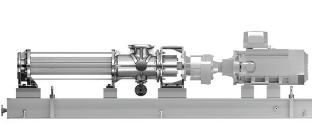
Peter Vila, Managing Director of SEEPEX Australia, is a progressive cavity pump expert. He has been involved with pumps for over 35 years. Peter spent the first five years repairing pumps and the following 30 years in technical sales, 15 of which have been with SEEPEX progressive cavity pumps.
For more information on progressive cavity pumps, please contact SEEPEX Australia on (02) 4355 4500 or at info.au@seepex.com
Global


67 www.pumpindustry.com.au pump industry | Summer 2019 | Issue 26 ASK AN EXPERT
1300 670 060 Leading the industry in service standards
Full API progressive cavity pump.
www.franklin-electric.com.au
industry-leading technical service, robust training programs,
unwavering support and communication.
presence, personal service Franklin Electric uses the experience gained over 50 years to ofer
and
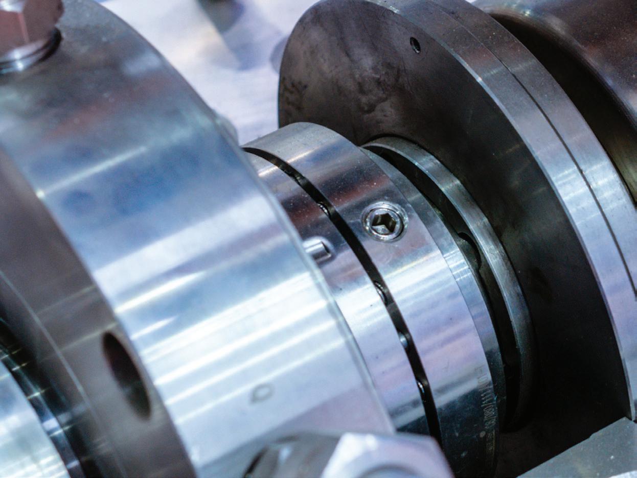
SELECTING AND APPLYING SLURRY PUMPS (PART 2)
Construction materials
Due to the diverse range of slurry applications, a large variety of metals and elastomers are available for slurry pump wetted parts. Proper material selection will depend on the properties of the slurry — erosive, corrosive or both — and on the basic pump design.
Material selection can often be a compromise between erosion and corrosion resistance properties in order to achieve optimum wear life for any specifc installation.
Metals resist erosion through a combination of hardness and toughness, and resist corrosion by forming a passivated surface layer that protects against further corrosion. However, in slurry services, this passive layer is continually being worn away and exposing new metal surfaces.
Elastomers resist erosion though resilience and tear resistance. They are soft, allowing solid particles to rebound without damaging the elastomer by abrasion or fracture. Large or sharp particles may tear the elastomer, so material selection should be carefully
matched to the slurry. The basic chemical resistance of an elastomer will determine its performance in a corrosive environment.
Figure 1 summarises the properties of various materials commonly used in slurry applications.
Hard irons
Hard irons are used for the most erosive slurries, as well as those with weak acid or caustic carriers. These are classifed as chromium-nickel (NiHard), chromium-molybdenum and highchromium white irons. These irons can
Figure 1: General properties of weted materials
68 pump industry | Summer 2019 | Issue 26 www.pumpindustry.com.au
PUMP HANDBOOK Wetted material Abrasive characteristics of slurry Applicable wear service class Corrosive characteristics of slurry Grey cast iron Very mild, fine particles 1 Non corrosive Ductile iron Moderate 2 Non corrosive White irons Severe 4 Mildly corrosive Martensitic stainless steel Moderate 3 Mildly corrosive Austenitic stainless steel Mild 1 Highly corrosive Duplex stainless steel Moderate 2 Corrosive Elastomers Severe, fine particles 3 Mildly corrosive
The PIA’s Australian Pump Technical Handbook is a cornerstone text for the Australian pump industry and, in our opinion, a must have for anyone who deals with pumps on a regular basis. In this ongoing series, we feature abridged chapters from the classic book to showcase the various areas covered and to reacquaint readers with the technical aspects of pumps. In this issue, we continue to look at selecting and applying different types of slurry pumps.
normally be used for slurries with pH values between 3.5 and 10.0, depending on the chloride level. At zero chlorides for example, a pH of 4.5 is satisfactory, whereas at 20,000 ppm chlorides the pH is limited to 6.5.
Stainless steels
Stainless steels should be used for more severe corrosive applications, however it should be noted that its erosive resistance is much lower than hard irons.
Martensitic stainless steels are used for mildly corrosive applications as they are the most wear resistant type of stainless steel.
On the other hand, austenitic stainless steels are used for highly corrosive applications, but are limited to very light slurry applications.
Duplex stainless steels provide better corrosion resistance than martensitic steels and better erosion resistance than austenitic steels. They are used for light slurries with aggressive carrier liquids.
Elastomers
The most commonly used polymer is natural rubber, which is usually defned
by having a specifc gravity of <1.0, hardness of approximately 40 Shore A, and very high resilience. The high resilience gives maximum abrasion resistance, providing the slurry particles are not too large (<6mm or 0.25”) or too sharp which causes excessive cutting and tearing. Natural rubber components are chemically resistant to most slurries that are mildly acidic or basic, and at temperatures less than about 80°C (180°F).
The synthetic rubber polychloroprene (or neoprene) is used for increased heat resistance up to 100°C (212°F) and moderate oil resistance. It is not as abrasion resistant as natural rubber.
Polyurethane is often used for fneparticle slurries as it is much harder than other elastomers with the same resilience, so increased impeller tip speeds are possible. Oil and solvent resistance is good. Care should be taken to select the proper type of urethane to prevent problems with hydrolysis in hot service (80°C or 180°F maximum).
Shaft sealing
The type of seal ftted in a slurry pump is a very important design
consideration as leakage of the process fuid is undesirable and can present a safety hazard. It is recommended that users consult with slurry pump suppliers to optimise the seal selection for the conditions of service likely to be encountered.
Three types of shaft seal are found in slurry pumps. The simplest, but most prone to leakage, is a gland seal with the packing rings running on a hard metal shaft sleeve that requires continuous fow of fushing water to minimise sleeve wear.
Where seal leakage must be minimised (eg. with an acidic or caustic carrier fuid), a mechanical seal specially designed for slurry service may be used. Slurry mechanical seals generally require fushing and cooling, either with water or with a barrier fuid compatible with the process fuid. Mechanical seals are the only option for slurry pumps driven by submersible motors.
Where it is not acceptable to add water to the process fuid through the shaft seal, a hydrodynamic or centrifugal seal (also called an expeller seal) can be run without fushing water. This comprises a small secondary impeller
69 www.pumpindustry.com.au pump industry | Summer 2019 | Issue 26 PUMP HANDBOOK
that reduces the pressure at the throat bush to atmospheric, and a packing ring or V-ring static seal to prevent leakage when the pump is stationary. A hydrodynamic seal absorbs about three to fve per cent additional power.
Slurry properties
It is important to obtain full details of the slurry properties to make a prediction of wetted components wear life, and thus arrive at a proper pump selection. Considerations are the abrading mineral itself, abrasive hardness, particle velocity, density, sharpness, shape and size, and the temperature and chemical properties of the carrier fuid.
While metals can withstand higher temperatures than elastomers, the
temperature limitation for a metal pump is likely to depend on non-metallic wetted materials such as seals and gaskets.
The minimum information required on particle size of entrained solids is the d50 size, ie. the screen mesh size through which 50 per cent of particles will pass, and also the maximum particle size.
The basic pump wetted materials properties and selection criteria for various slurry properties are summarised in Figure 2.
Series pumping
If a system design requires a slurry pump to deliver a greater dynamic head than the limits shown in Figure 2, or greater than the pump manufacturer’s performance limit, it may be necessary to install two or more pumps in a series.
Slurry properties
Solids particle size d50 >1mm (0.04”) d50 <6mm (0.25”)
Particle sharpness Large, sharp Small, rounded
Acidity pH = 4.5-10 pH <6 pH <8
Hydrocarbons Suitable
Unsuitable Moderate effect
Chloride present <100ppm @ pH = 4.5 <1000ppm @ pH = 7 Suitable
Hydrochloric acid Unsuitable Suitable Moderate effect
(180°F)
Sulphuric acid
Impeller peripheral velocity - max
Pump limitations
(155ft/sec)
(90ft/sec)
Differential headmax 100m (330ft) 40m (130ft)
(180°F)
Pumps connected in series close to each other (ie. with minimal pipe friction loss between pumps), should have a casing pressure rating sufcient for the total pressure (ie. the sum of the suction pressure and the pump developed pressure), allowing a safety factor of at least 50 per cent to cope with momentary pressure spikes.
Slurry head correction
A derating of pump total head is usually necessary because of the presence of solids in the slurry. Suction losses within the pump increase as the density of the slurry increases. Additionally, slip occurs between the transporting fuid and the solid particles as the slurry passes through the pump impeller, which produces energy loss. Because of the variability of slurries, pump manufacturers provide curves showing performance when pumping clear water. To select the appropriate pump and motor combination using the manufacturer’s performance curve, the total head for slurry should be expressed in terms of equivalent water head.
Formulae have been developed for calculating correction factors for head and efciency based on solids particle size and slurry specifc gravity. These correction factors are applied to transform the required slurry head (or efciency) into equivalent water values.
The slurry viscosity further afects the pump total head and the hydraulic efciency. Viscosity efects should be considered when calculating the equivalent water duty for a slurry service.
The pump absorbed power derived for water is multiplied by the slurry specifc gravity to calculate the power required to pump the slurry.
(105ft/sec)
(105ft) Temperature - max Limited by gasket materials
(170°F)
Further information and detailed diagrams, equations and schematics can be found in the Australian Pump Technical Handbook, available from the PIA website. In the next edition of Pump Industry, we continue our explorations into the selection and application of slurry pumps.
70 pump industry | Summer 2019 | Issue 26 www.pumpindustry.com.au
PUMP HANDBOOK
Pump materials White iron Rubber Polyurethane
Below 80°C
Suitable Unsuitable
Nitric acid
<10%conc
Suitable <10%
at ambient
conc
47m/s
28m/s
32m/s
80°C
75°C
46m
Figure 2: Slurry pump materials selection criteria

PUMP SCHOOL

Restarting motor-driven centrifugal pumps after power failure
With storm season fast approaching it is always best to be prepared. Although we cannot control the weather, we can have these simple measures in place to help minimise down time and get your pump up and running again after the storm has passed.
Assuming that power failure will not cause the centrifugal pump to go into reverse rotation, that is, that a check valve will protect the pump against reverse fow, there is generally no reason why the pump would be permitted to restart once the current has been reestablished. Whether the pump will start again automatically when the power is restored will depend on the type of motor control logic used.
Because pumps operating on a suction lift may lose their prime during the time that power is of, it is preferable to use starters with low load protection for such installations to prevent an automatic restart. This does not apply, of course, if the pumps are automatically primed, or if some protection device is incorporated so that the pump cannot run unless it is primed.
Starting the pump
Assuming that the centrifugal pump in question is motor-driven, that its shutof power does not exceed the safe motor power, and that it is to be started against a closed or cracked open gate valve, the starting procedure is as follows:
1. Prime the pump, opening the suction valve, closing the drains, etc. to prepare the pump for operation
2. Open the valve in the cooling water supply to the bearings, where applicable
3. Open the valve in the cooling water supply if the stufng boxes are water cooled
4. Open the valve in the sealing liquid supply if the pump is so ftted
5. Open the warm-up valve of a pump handling hot liquids if the pump is not normally kept at operating temperature. When the pump is warmed up, close the valve
6. Open the valve in the recirculating line if the pump should not be operated against dead shut of (if ftted) or slightly crack open the discharge valve
7. Start the motor
8. Open the discharge valve slowly
9. Observe the leakage from the stufng boxes and adjust the sealing liquid valve for proper fow to ensure the lubrication of the packing. If the packing is new, do not tighten up on the gland immediately, but let the packing run in before reducing the leakage through the stufng boxes
10. Check the general mechanical operation of pump and motor, for example, bearing temperature, noise vibration
11. Close the valve in the recirculating line once there is sufcient fow through the pump to prevent overheating
If the pump is to be started against a closed check valve with the discharge gate valve open, the steps are the same, except the discharge gate valve is opened prior to the motor being started. In certain cases, the cooling water to the bearings and the sealing water to the seal cages are provided by the pump. This, of course, eliminates the need for the steps listed for the cooling and sealing supply.
71 www.pumpindustry.com.au pump industry | Summer 2019 | Issue 26 Article courtesy of Kelair Pumps Australia “When Pump Knowledge Matters” Phone: 1300 789 466 or visit www.kelairpumps.com.au
72 pump industry | Summer 2019 | Issue 26 www.pumpindustry.com.au ADVERTISERS’ INDEX ABB 13 Adelaide Control Engineering ................. 37 ASM PUMPS .................................................. 31 AW Austworld 45 Barron - Auma Australia 47 Brown Brothers Engineers 11, 33 Capari Pumps Australia ............................ 23 CNH Industrial ............................................. 29 Crusader Hose 21 Deutz Australia 1 Drive Systems IFC EagleBurgmann Australasia....................... 9 Ebara Pumps Australia ............................... 19 FLOWROX 35 Franklin Electric 67 Hydro Innovations 25 Jacmor Engineering ................................... 63 Kelair Pumps Australia............................... 61 KSB Australia 57 Lafert Electric Motors Australia 27 Midwest Valves & Controls 30 Pioneer Pump ........................................... OBC Rathi Polybound .......................................... 39 Seamech 3 SEEPEX Australia 17 Startco 7 United Pumps Australia............................ 43 University of British Columbia................. 12 VescoPlastics 16 Vogelsang 55 WEG Australia 59, 65 Welling & Crossley ....................................... 10 Zetco Valves ............................................... IBC
Subscribe NOW www.pumpindustry.com.au/subscribe/ AUTUMN 2019 Deadline: 8 March 2019 MAIN FEATURE Also featuring DISTRIBUTION Water Seals Motors & drives Irrigation HVAC Manufacturing WIOA QLD Austmine OzWater National Manufacturing Week WINTER 2019 Deadline: 7 June 2019 MAIN FEATURE Also featuring DISTRIBUTION Mining Coal seam gas Wastewater Recycling Food WIOA Bendigo AIMEX SPRING 2019 Deadline: 13 September 2019 MAIN FEATURE Also featuring Energy efciency Smart pumps Training Plus the 2020 Industry Capability Guide SUMMER 2020 Deadline: TBA MAIN FEATURE Also featuring DISTRIBUTION Oil & gas State of the industry Valves Fire Power generation WIOA NSW
Editorial schedule

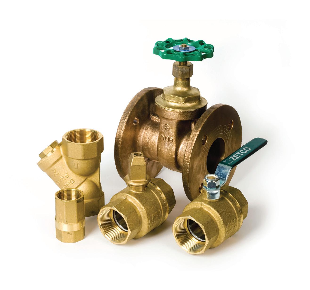
are you ready to comply? WaterMarked valves to suit your requirements. zetco.com.au 1300 659 639 1968-2018 years